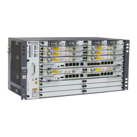
Huawei OptiX RTN 950 User manual

HUAWEI TECHNOLOGIES CO., LTD.HUAWEI TECHNOLOGIES CO., LTD.
OptiX RTN 950 Radio OptiX RTN 950 Radio
Transmission System V100R002Transmission System V100R002
IDU Quick Installation GuideIDU Quick Installation Guide
OptiX RTN 950OptiX RTN 950
无线传输系统无线传输系统
V100R002V100R002
IDUIDU
快速安装指南快速安装指南
Issue: 04Issue: 04
Date:2010-04-20Date:2010-04-20
文档版本:文档版本:
0404
发布日期:发布日期:
2010-04-202010-04-20

Huawei Technologies Co., Ltd. provides customers Huawei Technologies Co., Ltd. provides customers
with comprehensive technical support and service.with comprehensive technical support and service.
For any assistance, please contact our For any assistance, please contact our
local office or company headquarters.local office or company headquarters.
Huawei Technologies Co., Ltd.Huawei Technologies Co., Ltd.
Address: Address:
Huawei Huawei
Industrial Industrial
BaseBase
Bantian, LonggangBantian, Longgang
Shenzhen 518129Shenzhen 518129
People's Republic of ChinaPeople's Republic of China
Website:Website:
http://www.huawei.comhttp://www.huawei.com
Email:Email:
No part of this document may be reproducNo part of this document may be reproduc
ed or transmitted in anyed or transmitted in any
form or by any means without priorform or by any means without prior
written consent of Huawei Technologies Co., Ltd.written consent of Huawei Technologies Co., Ltd.
Copyright ©Copyright ©
Huawei Technologies CHuawei Technologies C
o., Ltd. 2010. All ro., Ltd. 2010. All r
ights reserved.ights reserved.
Trademarks and PermissionsTrademarks and Permissions
and other Huawei trademarks are trademarks of Huawei Technologies Co., Ltd.and other Huawei trademarks are trademarks of Huawei Technologies Co., Ltd.
All other trademarks and trade names mentioned in this document are the property of their respectiveAll other trademarks and trade names mentioned in this document are the property of their respective
holders.holders.
NoticeNotice
The information in this document is subject to change without notice. Every effort has been made in theThe information in this document is subject to change without notice. Every effort has been made in the
preparation of this document to ensure apreparation of this document to ensure a
ccuracy of the contents,ccuracy of the contents,
but all statements, information, andbut all statements, information, and
recommendations in this document do not constitute the warranty of any kind, express or implied.recommendations in this document do not constitute the warranty of any kind, express or implied.
Huawei Technologies ProprietaryHuawei Technologies Proprietary
ContentsContents
目录目录
Tools for InstallationTools for Installation
安装工具安装工具
55
PrecautionsPrecautions
注意事项注意事项
11
Introduction to the IDUIntroduction to the IDU
IDUIDU
介绍介绍
66
Introduction to InterfacesIntroduction to Interfaces
接口介绍接口介绍
66
Introduction to Installation Holes on Both Sides of the ChassisIntroduction to Installation Holes on Both Sides of the Chassis
机盒侧面安装孔位介绍机盒侧面安装孔位介绍
66
88
Installing tInstalling t
he Chashe Chas
sissis
on the Waon the Wa
llll
在墙面上安装机盒在墙面上安装机盒
1010
Installing tInstalling t
he Chashe Chas
sissis
on the Deson the Des
kk
在桌面上安装机盒在桌面上安装机盒
1313
88
Installing the IDUInstalling the IDU
安装安装
IDUIDU
Installing the Chassis in the ETSI CabinetInstalling the Chassis in the ETSI Cabinet
ETSIETSI
机柜中安装机盒机柜中安装机盒
99
Installing the Chassis in the 19-Inch CabinetInstalling the Chassis in the 19-Inch Cabinet
1919
英寸机柜中安装机盒英寸机柜中安装机盒
Installing the BoardInstalling the Board
安装单板安装单板
1515
Installing the IDU CablesInstalling the IDU Cables
安装安装
IDUIDU
的线缆的线缆
1515
FlowFlow
流程流程
77
Installing FlowInstalling Flow
安装流程安装流程
77
CommComm
issiissi
oninonin
gg
FloFlo
ww
调测流程调测流程
88
1313
Installing the PGND Cable on the E1 PanelInstalling the PGND Cable on the E1 Panel
安装安装
E1 panelE1 panel
的保护地线的保护地线
1414
1313
Optional: InstallinOptional: Installin
g the g the
E1 PanelE1 Panel
可选:安装可选:安装
E1 PanelE1 Panel
11
22
11
33
44
22
11
22
11
33
22
1414
Fixing the Floating NutsFixing the Floating Nuts
固定浮动螺母固定浮动螺母
Fixing the E1 PanelFixing the E1 Panel
固定固定
E1 panelE1 panel

Contents
目录
Powering On the Equipment
接通设备电源
25
11
23
10
22
Installing the External Clock Cable
安装外时钟电缆
Aligning the
Single-Pola
rized Antennas
对调单极化天线
1
27
Aligning the
Dual-Polari
zed Antennas
对调双极化天线
2
28
12
24
Checking the Status of a Radio Link
检查微波链路状态
29
Configuring the NE Data (by Using the
U2000 LCT)
配置网元数据
(
使用
U2000 LCT)
26
Aligning the Antennas
对调天线
27
Installing the
Order
wire
Phone Lin
e
安装公务电话线
9
21
Installing the Ethernet Service Network Cable
安装以太网业务网线
7
20
Installing the NM Cable
安装网管电缆
8
20
Installing the E1 Cable
安装
E1
电缆
6
19
Installing the XPIC cable
安装
XPIC
电缆
3
17
Installing the IF Jumper
安装中频跳线
4
18
Installing the Fiber Jumper
安装尾纤
5
18
Checking the Installation
安装检查
30
Installing the Asynchronous and Synchronous Date Cable
安装异步和同步数据电缆
Installing the External Alarm Cable
安装外接告警电缆
Installing the Power Cable
安装电源线
16
15
Installing the PGND Cable
安装保护地线
2
1

1
Precautions
注意事项
This document aims to provide simple and distinctive guideli
nes for hardware installation.
本文档用于为设备硬件安装提供简明快捷的操作指导。
This document does not describe operations for the pre-delivery installation.
Instead, this document
describers only the operations for on-site installation.
本文档对于出厂前已完成的安装操作不进行介绍,仅对现场安装涉及的操作进行介绍。
Electrostatic Discharge
静电
Before touching the device, or holding the boards and IC
chips, wear the anti-static gloves or anti-static wrist strap
to prevent the electrostatic discharge of the human body
from damaging the sensitive components. Ensure that
the other end of the anti-static wrist strap is well
grounded.
在接触设备,手拿插板、单板、
IC
芯片等之前,为防止人
体静电损坏敏感元器件,必须佩戴防静电手套或者防静电
手腕,并将防静电手腕的另一端良好接地。
Bundling Cables
绑扎线缆
The distance between cable ties or fiber binding straps inside
the cabinet should be within 250 mm. (For
subscriber cable, the distance is 200 mm. )
在机柜内部,线扣
/
光纤绑扎带的绑扎间隔不超过
250mm
。(用户电缆在机柜内线扣的绑扎间隔不超过
200mm
。)
The distance between cable ties for all cables and
corrugated pipes outside the cabinet is determined
according to the distance between two horizontal beams. For the cabling trough without beams, bundle
the cables with the distance not exceeding 250 mm
between cable ties.
在机柜外部,所有线缆和波纹管的线扣绑扎距离以两横梁之间的间距为准,没有横梁的走线槽按照不超
过
250mm
的间距绑扎。
Checking Before Installation
安装前检查
Before starting installation, you should make the equipment room, power supply, ground
wire, optical
cables, and other facilities in the equipment ready. When
these installation conditions are confirmed, the
installation may begin according
to the pre-designed layouts.For
detailed requirements and
related
index, refer to Installation Reference.
在设备安装之前,要求检查机房、机柜、电源、地线、光缆以及配套设施。确定施工条件具备后,按照
工程设计文件进行施工。具体的设备运行要求和相关指标请参见《安装参考》。

2
1
1
2
2
3
3
1
1
2
2
3
3
纽子开关的位置及说明
打开开关
打开
关断
Precautions for Handling the Toggle Lever Switch
纽子开关操作注意事项
Before turning the toggle lever
switch, you must pull it out slightly.
纽子开关必须先轻轻拉起,才能拨
动。
•
Location and positions of the toggle lever
switch
I
: ON
O
: OFF
•
Turning on the switch
断开开关
•
Turning off the switch
Pull the switch out slightly.
轻拉
Turn the switch.
拨动
Release the switch.
释放
Pull the switch out slightly.
轻拉
Turn the switch.
拨动
Release the switch.
释放

3
Power off the ODU.
关断
ODU
电源
Connect or disconnect the IF jumper.
连接/断开中频跳线
Precautions for Handling the IF Jumper
中频跳线操作注意事项
Before removing or inserting the IF jumper, you
must power off the ODU.
必须先关断
ODU
电源,才能拔插中频跳线。
Do not remove or insert the IF jumper when the
ODU is powered on.
禁止在未关断
ODU
电源时带电拔插中频跳线!
Before removing or inserting the IF cable, you
must power off the ODU.
必须先关断
ODU
电源,才能拔插中频电缆。
Do not remove or insert the IF cable when the
ODU
is powered on.
禁止在未关断
ODU
电源时带电拔插中频电缆!
Power off the ODU.
关断
ODU
电源
Connect or disconnect the IF cable.
连接/断开中频电缆
Precautions for Handling the IF Cable
中频电缆操作注意事项
2
1
2
1

4
Remove the
IF board.
拔出中频单板
Power off the ODU.
关断
ODU
电源
Disconnect the IF Jumper.
断开中频跳线
Remove or insert the IF board.
拔出/插入中频单板
Precautions for Handling the IF Board
拔插中频单板操作注意事项
Before removing or inserting the IF board, you must power off the
ODU.
必须先关断
ODU
电源,才能拔插中频单板。
Insert the IF
board.
插入中频单板
Do not remove or insert the IF board when the ODU is powered on.
禁止在未关断
ODU
电源时带电拔插中频单板!
3
2
1
3

5
Tools for installation
安装工具
Tape Measure
长卷尺
Philips Screwdriver
十字螺丝刀
Flathead Screwdriver
一字螺丝刀
Adjustable Wrench
活动扳手
Level Bar
水平尺
Ratchet Crimp Tool
压线钳
Socket Wrench
成套套筒
Torque Wrench
力矩扳手
Allen Wrench
内六角扳手
Cable Cutter
断线钳
Wire Stripper
剥线钳
Network Cable Crimping
Pliers
网线钳
Diagonal Pliers
斜口钳
Crimping Tool
冷压钳
Sharp-nose Pliers
尖嘴钳
Pliers
钢丝钳
Bayonet Wrench
呆扳手
Paper Knife
裁纸刀
Claw Hammer
羊角锤
Percussion Drill
冲击钻
Marker Pen
划线笔
Ladder
梯子
Electric Iron
电烙铁
Antistatic Gloves
安装手套
Heat Gun
热风枪
Multimeter
万用表
Antistatic Gloves
防静电手套
Binding Strap
光纤绑扎带
Insulation Tape
电器绝缘胶带
Antistatic Wrist Strap
防静电腕带
Punching Wire Pliers
打线刀
File
锉刀
Cleaner
吸尘器

6
1
Introduction to Interfaces
接口介绍
Introduction to the IDU
IDU
介绍
2
Introduction to Installation Holes on Both Sides of the Chassis
机盒侧面安装孔位介绍
E1 interface
E1
接口
1
0
1
1
IF interface
中频接口
ODU power switch
ODU
电源开关
Input power interface
输入电源接口
Synchronous/Asynchronous data
interface
同
/
异步数据接口
External
clock/time
interface
外时钟
/
时间接口
Ethernet service interface
以太网业务接口
NM/COM interface
网管
/COM
接口
Orderwire phone interface
公务电话接口
External alarm interface
外接告警接口
According to different board configurations, the positions of the actual
IDU interfaces may be different from
the positions shown in the figures.
根据单板配置的不同,实际使用的
IDU
接口和图示接口位置可能会有区别。
Optical interface
光接口
10
11
Installation holes in the N63E/19-inch cabinet
N63E/19
英寸机柜安装孔
Before installing the chassis in the ETSI cabinet, adjust the
installation holes of the mounting ears according to
the type of the cabinet.
在
ETSI
机柜中安装机盒时,安装前需由机柜类型调整挂耳安装孔位。
Installation holes in the T63/T66/N66T cabinet
T63/T66/N66T
机柜安装孔
12
12
NE cascading interface
网元级联接口

7
1
Installation Flow
安装流程
Flow
流程
Installing the IDU
安装
IDU
Page 8 to
13
第
8-13
页
Optional: Installing the E1 Panel
可选:安装
E1 Panel
Page 13 to
14
第
13-14
页
Installing the Board
安装单板
Page 15
第
15
页
Installing the IDU Cables
安装
IDU
的线缆
Page 15 to
24
第
15-24
页
End
安装结束
Checking the Installation
安装检查
Page 30
第
30
页
Start
开始
Page 18
第
18
页
Page 17
第
17
页
Installing the Power Cable
安装电源线
Page 16
第
16
页
Installing the PGND Cable
安装保护地线
Page15
第
15
页
Page 19
第
19
页
Installing the Fiber Jumper
安装尾纤
Page 18
第
18
页
Page 20
第
20
页
Installing the NM Cable
安装网管电缆
Page 20
第
20
页
Installing the Orderwire Phone
Line
安装公务电话线
Page 21
第
21
页
Installing
the Extern
al Clock
Cable
安装外时钟电缆
Page 22
第
22
页
Installing
the Asynchronous
and
Synchronous Data Cable
安装异步和同步数据电缆
Page 23
第
23
页
Installing
the External
Alarm
Cable
安装外接告警电缆
Page 24
第
24
页
Installing the Chassis in the
ETSI Cabinet
在
ETSI
机柜中安装机盒
Page 9
第
9
页
Installing the Chassis in the 19-
Inch Cabinet
在
19
英寸机柜中安装机盒
Page 8
第
8
页
Page 13
第
13
页
Installing the Chassis on the
Wall
在墙面上安装机盒
Page 10
第
10
页
Installing the Chassis on the
Desk
在桌面上安装机盒
Installing the E1 Cable
安装
E1
电缆
Installing the Ethernet Service
Network Cable
安装以太网业务网线
Installing the IF Jumper
安装中频跳线
Installing the XPIC Cable
安装
XPIC
电缆

8
2
Com
mis
sio
ning
Flo
w
调测流程
1
Installing the Chassis in the 19-Inch Cabinet
19
英寸机柜中安装机盒
Installing IDU
安装
IDU
Fixing the floating nuts
固定浮动螺母
Removing the screws
拆下螺钉
Keep the removed screws properly for installing
the PGND cable in future.
请保留拆下的螺钉,后继安装保护地线需要使用。
When tightening the floating nuts, ensure that that a
minimum of 25
mm space on
the left and
right sides
of
the
IDU is reserved for ventilation.
固定浮动螺母时,保证
IDU
安装后
IDU
左侧和右侧至少有
25mm
通风空间。
floating nut
浮动螺母
installation
hole
安装孔
Powering On the
Equipment
接通设备电源
Page 25
第
25
页
Optional: Configuring the NE
Data (by Using the Web LCT)
可选:配置网元数据
(
使用
Web
LCT)
Page 26
第
26
页
Aligning the Antennas
对调天线
Page 27 to
28
第
27-28
页
End
结束
Checking the Status of a Radio
Link
检查微波链路状态
Page 29
第
29
页
Start
开始
Aligning the Dual-Polarized
Antennas
对调双极化天线
Page 28
第
28
页
Aligning the Single-Polarized
Antennas
对调单极化天线
Page 27
第
27
页

9
Before installing the chassis in an ETSI cabinet, adjust
the installation holes
of the mount
ing ears
according to
the cabinet type.
在
ETSI
机柜中安装机盒时,安装前需由机柜类型调整挂
耳安装孔位。
Installing the chassis in the cabinet
安装机盒到机柜中
Installing the PGND cable
安装保护地线
Installing the PGND cable by using the removed screws
用拆下来的螺钉安装保护地线
Installing the mounting ears
安装转接挂耳
2
Installing the Chassis in the ETSI
Cabinet
ETSI
机柜中安装机盒
Fixing the floating nuts
固定浮动螺母
Mounting ears
转接挂耳
M6 screw assembly
M6
组合螺钉
When tightening the floating nuts, ensure that that a
minimum of 25 mm spa
ce on the left and r
ight sides
of
the IDU is reserved for ventilation.
固定浮动螺母时,保证
IDU
安装后
IDU
左侧和右侧至少有
25mm
通风空间。
2.0
±
0.2 N·M
M6
1.4
±
0.14 N·M
M4
3.0
±
0.3 N·M
M6
floating nut
浮动螺母
installation hole
安装孔
To the grounding point on the rack column of the
cabinet or the indoor grounding bar.
至机柜立柱接地点或室内接地排
Install the conducting wire support if provided.
如果配发导线架,请安装。

10
Installing the PGND cable
安装保护地线
Installing the chassis in the cabinet
安装机盒到机柜中
Installing the PGND cable by using the removed screws
用拆下来的螺钉安装保护地线
Removing
the mou
nting e
ars
拆下挂耳
Positioning and drilling the holes (1)
定位并打孔(
1
3
Installing the Chassis on the Wall
在墙壁上安装机盒
8
Position the mounting ear on the wall, drill the holes, and
install the bolts. After the installation, ensure that a
minimum of 50 mm space on the upper and l
ower sides
of
the IDU is
reserved for
ventilation.
用挂耳在墙壁上定位安装位置,然后打孔并敲入螺栓。保
证
IDU
安装后
IDU
上侧和下侧至少有
50mm
通风空间。
≥
300mm
1.4
±
0.14 N·M
M4
2.0
±
0.2 N·M
M6
To the grounding point on the
rack column of the cabinet or
the indoor grounding bar.
至机柜立柱接地点或室内接地排
Install the conducting wire support if provided.
如果配发导线架,请安装。

11
Rotate the mounting ears to 90 degrees. Install the
mounting ears in the direction as shown in the figure.
将挂耳旋转
90
0
,按照图示方向安装挂耳。
Installing the mounting ears
安装挂耳
Installing the conducting wire support (optional)
安装导线架(可选)
Installing the conducting wire support (optional)
安装导线架(可选)
Expected Installation Effect
安装完成效果图
If the conducting wire frame is provided, install it
according
to the illustration in the
figure.
Otherwise, go to S
tep g.
如果配发导线架,请如图示安装,否则直接从步骤
g
继续安
装。

12
8
When installing the chassis on the wall, place the fan assembly
in the lower part of the chassis for heat dissipation.
墙面安装机盒时,风扇板要位于机盒下方,以利于机盒散热。
Positioning and drilling the holes (2)
定位打孔(
2
Ф
8 holes with a
depth of 52 mm to
60 mm
Ф
8
、深度
52mm
~
60mm
的
孔
Mount the equipment onto the bolts installed on the
wall. Then, use the marker pen to mark the positions
of
the
mou
nti
ng
ear
s.
将设备挂在已安装好的墙壁螺栓上,然后用记号笔记录下面挂耳的打孔位置。
Remove the equipment and drill the holes at the marked positions.
取下设备,根据记录位置打孔。
Installing the chassis on the wall
安装机盒到墙壁上
Installing the PGND cable
安装保护地线
Fan assembly
风扇板
M6x60 expansion bolt
M6
×
60
的膨胀螺栓
Nut
螺母
Big flat washer
大平垫
Small flat
washer
小平垫
PGND cable
保护地线
Marking the hole locations
标记打孔位置
1.4
±
0.14 N·M
M4

13
Installing the plastic foot
安装脚垫
Installing the PGND cable
安装保护地线
4
Installing the Chassis on the Desk
在桌面上安装机盒
Do not place any object near the ventilation holes
on the two sides of the cabinet.
Otherwise, heat
dissipation is affected.
机盒两侧通风口请不要放置任何物品,以防止影响
风扇散热。
Plastic foot
脚垫
PGND cable
保护地线
Installing the PGND cable by using the removed screws
用拆下来的螺钉安装保护地线
1
Fixing the Floating Nuts
固定浮动螺母
Optional: Installi
ng the E1
Panel
可选:安装
E1 Panel
Removing the mounting ears and Installing the plastic foot
拆下挂耳并安装脚垫
1.4
±
0.14 N·M
M4
Floating nut
浮动螺母
Installation hole
安装孔

14
2
Fixing the E1 Panel
固定
E1 panel
3
Installing the PGND Cable on the E1
Panel
安装
E1 panel
的保护地线
To the grounding point on the
rack column of the cabinet or the
indoor grounding bar.
至机柜立柱接地点或室内接地排

15
Installing the Board
安装单板
1
Loosen the screws on the filler panel and remove the filler panel.
松开假面板的螺钉,拔出假面板。
Hold the ejector levers on the panel with hands and push
them outwards so that the angle between the
ejector lever and the panel is approximately 45 degrees. Push
the board gently along the guide rail until the
board cannot slide further.
两手捏住面板上的扳手,将其向两侧扳开,使扳手与面板成约
45º
的夹角,沿着插槽导轨平稳滑动插入单板,直
到单板无法向前滑动为止。
Apply proper force to clip the two ejector levers
of the board.
内扣单板的两个扳手。
Tighten the screws on the panel.
拧紧面板上的螺钉。
When installing, inserting, or removing the board, wear an antistatic wrist strap or antistatic
gloves. Before you insert a
board, ensure that the slot is correct. If
it is difficult to insert the board, stop the operation.
安装或者拔插单板时,请佩戴防静电手腕或者防静电手套。单板插入前请确认机盒槽位是否正确,遇到较大阻力时,请
勿强行插入。
2
3
4
If the PGND cable is installed in the ETSI cabinet,
connect the PGND cable to the grounding point
that is on the left side of
the chassis.
在
ETSI
机柜中安装保护电线时,将保护地线安装在
机盒左侧的接地点。
If the
PGND cable
is installed in the 19-inch cabinet,
connect
the PGND cable to the grounding point of t
he left mounting ear
of the chassis.
在
19
英寸机柜中安装保护电线时,可以将保护地线安装在
机盒左侧挂耳的接地点。
1
Installing the PGND Cable
安装保护地线
Installing the IDU Cables
安装
IDU
的线缆
Guide rail
导轨
This manual suits for next models
1
Table of contents
Other Huawei Microphone System manuals

Huawei
Huawei OptiX RTN 980L V100 User manual

Huawei
Huawei OptiX RTN 600 Technical specifications

Huawei
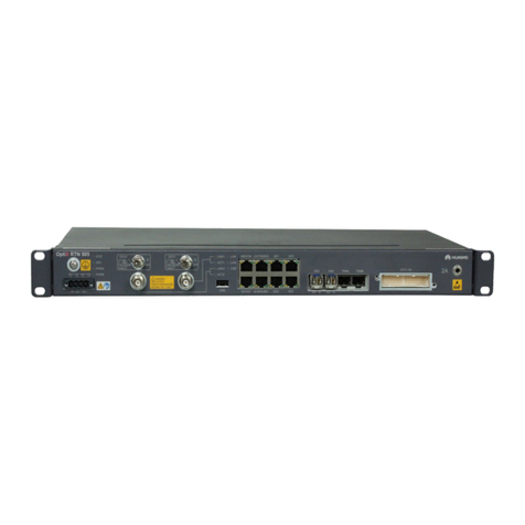
Huawei OptiX RTN 905 User manual

Huawei
Huawei OptiX RTN 320F User manual

Huawei
Huawei OptiX RTN 980 User manual

Huawei
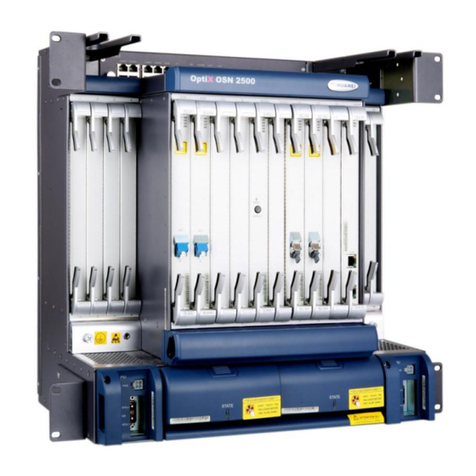
Huawei OptiX OSN 2500 User manual

Huawei
Huawei RTN 360 V100 User manual

Huawei
Huawei OptiX RTN 980 User manual

Huawei
Huawei OptiX OSN 550 User manual

Huawei
Huawei RTN XMC ODU Technical specifications