Huawei OptiX RTN 320F User manual

Address: Huawei Industrial Base
Bantian, Longgang
Shenzhen 518129
People's Republic of China
Website: http://www.huawei.com
Email: [email protected]
No part of this document may be reproduced or transmitted in any form or by any means without prior
written consent of Huawei Technologies Co., Ltd.
and other Huawei trademarks are trademarks of Huawei Technologies Co., Ltd.
All other trademarks and trade names mentioned in this document are the property of their respective
holders.
The purchased products, services and features are stipulated by the contract made between Huawei and
the customer. All or part of the products, services and features described in this document may not be
within the purchase scope or the usage scope. Unless otherwise specified in the contract, all statements,
information, and recommendations in this document are provided "AS IS" without warranties, guarantees
or representations of any kind, either express or implied.
The information in this document is subject to change without notice. Every effort has been made in the
preparation of this document to ensure accuracy of the contents, but all statements, information, and
recommendations in this document do not constitute a warranty of any kind, express or implied.
HUAWEI TECHNOLOGIES CO., LTD.
Issue 04
Date 2020-04-30

Safety Precautions
Thunderstorms
Do not work with electrical current or work in elevated or exposed locations during a thunderstorm.
Extreme weather conditions
OAU 2F is usually installed outdoors. If weather conditions are extreme during an installation, personnel
should follow the related local guidelines and regulations to safeguard personal health and safety.
Microwave
High-power radio frequency signals are harmful. Avoid exposure to transmission from the antennas of
microwave equipment that has the radiation warning symbol ( ). When you are installing or
performing maintenance on an antenna located on a tower that has multiple antennas, avoid exposure to
radiation from other antennas.
Elevated locations
OAU 2F is usually installed in an elevated location, for example, on the rooftop of a building. For installation
in elevated locations, installation personnel must:
Have the proper training and qualifications, and meet health requirements.
Wear helmets, safety belts, and anti-slip footwear.
Wear clothing and gloves appropriate to weather conditions.
Work in teams of two or more.
Test hoisting tools before use.
Avoid installation during extreme weather conditions, such as during thunderstorms, blizzards, or gales.
In addition, all site visitors must wear helmets.
High temperature
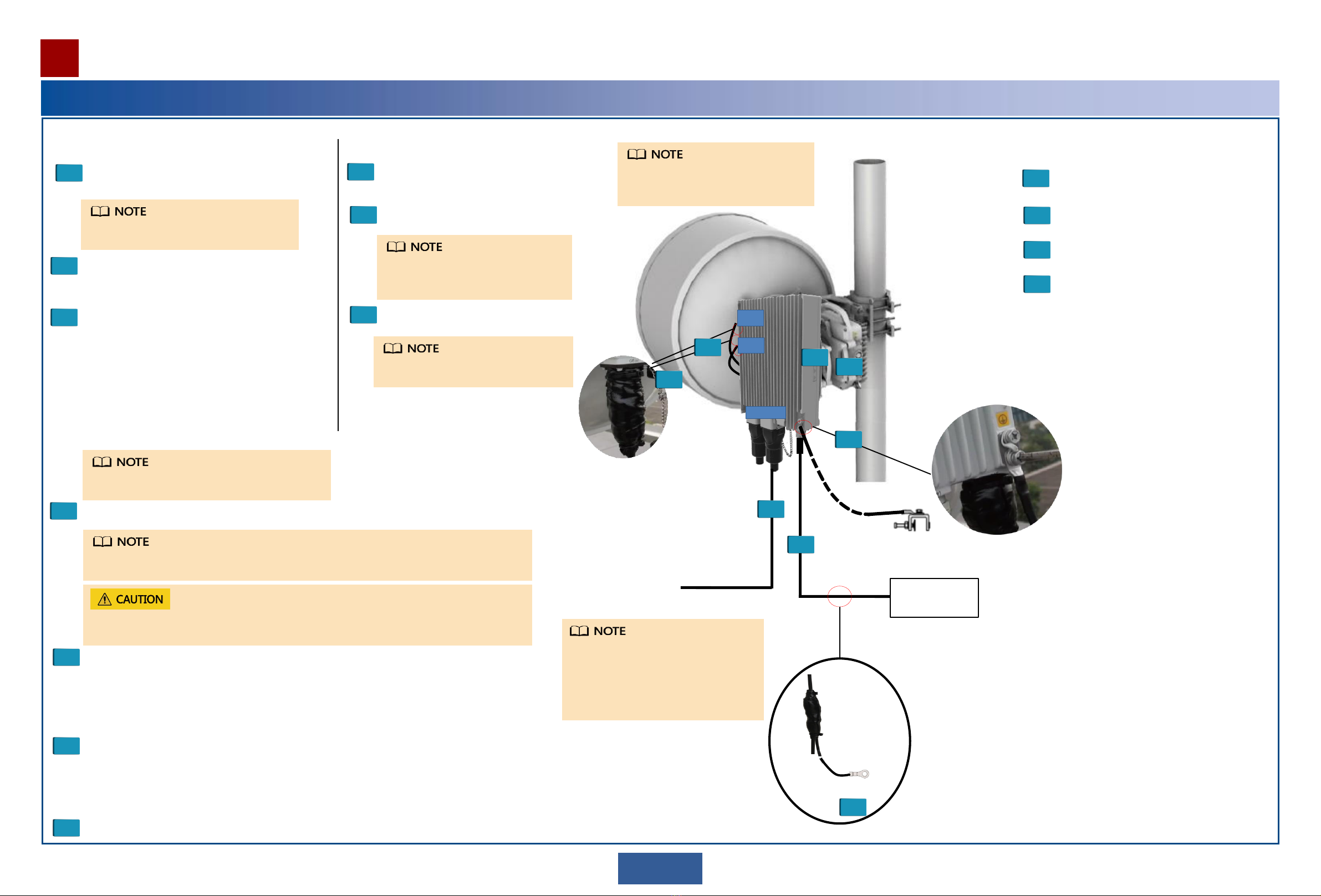
If the ambient temperature reaches 55°C, the surface temperature of an OAU 2F may exceed 70°C.
Therefore, wear protective gloves when handling the OAU 2F. A high-temperature warning label ( ) is
attached to each OAU 2F.
Corrosion
Anti-corrosion measures are required if an OAU 2F is installed in a location that is prone to corrosion. Contact the
local Huawei office for details. A location is prone to corrosion if it is:
Within 3.7 km of an ocean or a salt water lake
Within 3 km of a heavy pollution source, such as a smelting factory or coal mine
Within 2 km of a medium pollution source, such as a chemical, rubber, or electroplating plant
Within 1 km of a light pollution source, such as a food/leather processing plant or heating boiler
Unpacking
After unpacking an OAU 2F, power it on within 24 hours.
Do not power off an OAU 2F for more than 24 hours during maintenance.
Handling of OAU 2F or mounting kits
Wear clean gloves when handling the OAU 2F or mounting kits.
Moving and hoisting heavy objects
To move or hoist heavy objects, use appropriate equipment and adhere to the
following guidelines:
All personnel should wear helmets and protective clothes, gloves, and shoes.
Move heavy objects along a flat obstacle-free path.
Do not lift heavy objects by hand. Use appropriate equipment instead.
When items are hoisted, ensure that those standing nearby are safe from falling objects.
Use hoisting tools properly. Do not exceed load allowances to prevent damage to pulleys or slings.
Lasers
Do not look into an optical port without eye protection.
Local rules and regulations
If local rules and regulations require that anti-corrosion measures must be taken for ground connections, comply with
local rules and regulations.
1

Safety Precautions
DC power
The OAU 2F (DC option) supports only DC power supply. The OAU 2F (P&E option) supports only P&E power
supply.
Do not install or remove a live power cable. Any contact between the power cable core and a conductor can
generate electric arc or sparks, which may cause fire or eye injury.
Connect the power cables correctly to the positive and negative terminals of the power supply device. The
recommended fuse capacity is 7 A to 10 A.
Do not connect the OAU 2F to an AC power supply device. Otherwise, the OAU 2F may be damaged.
Do not connect the OAU 2F to a DC power supply device providing power beyond the range of –38.4 V to –57.6 V.
Otherwise, the OAU 2F may be damaged.
Do not leave any service cable unconnected.
Do not leave any service cable unconnected (see the following figure).
If a service port is not in use, remove the cable from it and plug it with a waterproof block.
IF port protection
If an IF port is not in use, cover it with a protective cap delivered with the equipment.
Protective cap
2
Power supply port
Do not leave any service cable unconnected.
OAU 2F (DC option) OAU 2F (P&E option)
GE P&E NMS MGMT
P&E Protective cap

AAppearance and ports
Equipment Components
Equipment Introduction
Front view Bottom view
3
Side view
Mounting hole
of the joining kit MIMO1/CA port
GE2 power port
MIMO2 port
NMS port 10GE2(o) port
10GE1(o) port
GE1(e) port USB Power port
OAU 2F (DC option)
MIMO1/CA port
GE2 power port
MIMO2 port
NMS port 10GE2(o) port
10GE1(o) port
P&E port USB Power port
OAU 2F (P&E option)
OAU 2F (DC option)
OAU 2F (P&E option)
OAU 2F (DC option)
OAU 2F (P&E option)
Two types of OAU 2F are available for the RTN 320F: OAU 2F (DC option) and OAU 2F (P&E option). Except for the installation of the power cable, other installation operations are the same between the OAU 2F (P&E option) and the OAU 2F
(DC option). Unless otherwise specified, the OAU 2F (DC option) is used as an example.
USB
Back view
OAU 2F (DC option)
IF1 (IF port)
IF2 (IF port)
Conversion
plate
OAU 2F (P&E option)
IF1 (IF port)
IF2 (IF port)
Mounting hole
of the joining kit
Conversion
plate

Sealing cover
Device
connection
tray
OMT core body
Protective film
OMT frame
Equipment Components
Equipment Introduction
4
BAppearance and ports of the hybrid coupler
Antenna port
Standby tributary port
Main tributary port Front view
Top view
Oblique view
COMT
DMounting kit
Hose clamp
Wall mounting
Pole mounting
The mounting kit is used only when the OAU 2F and
XMC ODU are installed separately.
Port Name Identifier
Main tributary port MAIN
Standby tributary port STANDBY
For 7–11 GHz XMC-3 ODUs
EJoining kit
For 13–38 GHz XMC-3 ODUs
For full-band XMC-3H ODUs For full-band XMC-5D ODUs
ODU hook hole
Mounting hole
ODU hook hole
Mounting hole
ODU hook hole
Mounting hole Mounting hole
The joining kit is used only
when the OAU 2F and XMC
ODU are installed
separately.
Different XMC ODUs use
different joining kits.
Expansion
screw
For full-band XMC-5D ODUs
and 11GHz XMC-2H ODU

Equipment Introduction
5
Equipment Components
FCables
View A
A
Cable
connector
Cable sheath
Brown: 0 V power cable (connected to the
positive terminal of the power supply device)
Blue: -48 V power cable (connected to the
negative terminal of the power supply device)
)
Negative
(-)
(+)
Power supply device
SW
OT terminal Ground terminal
Ground cable
Outdoor fiber/cascade cable
DLC/UPC connector
DC cable Positive
The ground terminal can be connected to a ground bar or U-shaped ground clip. Connect
the ground terminal to whichever is the most appropriate for the scenario.
See the usage instructions released with the ground clip for details.
Terminating a Ground Cable with an OT Terminal
Strip the ground cable. A: OT terminal
B: ground cable
C: exposed cable conductor
L1: length of the exposed cable
Fit the exposed cable into the OT terminal. Crimp the OT terminal lug.
Mapping between the cross-sectional
area of a cable conductor (C) and the
length of an exposed cable (L1)
Crimp the OT
terminal lug.
Cross-sectional
Area of C (mm2)L1 (mm)
1 7
1.5 7
2.5 7
4 8
When you are skillful, you can determine L1
based on the length of the OT terminal lug.
When striping off the insulation layer of the
ground cable, take care not to damage or nick
the metal conductor of the cable. Ensure that the cable conductor does not protrude
more than 2 mm from the OT terminal. The crimping impression may differ depending
on the crimping tool used.
GUSB flash drive
The model recommended for the USB flash drive is Netac
U208 with a 4 GB capacity.
If a different model or capacity is required, contact Huawei
local offices.
The appearance of Netac U208 flash drives varies
depending on the vendor.
Only USB 2.0 is supported.

6
Terminating an Outdoor Network Cable with Shielded RJ45 Connectors
RJ45 connector crimping tool Diagonal pliers
Prepare the following tools.
Prepare an outdoor network cable and shielded RJ45 connectors.
1. Core wire
2. Aluminum foil
3. Braid shield
4. Outer jacket
5. Shielded RJ45 connector
Strip the cable.
Length of the stripped
cable: 20 mm Strip off the braid shield and
cut the aluminum foil and
unwanted materials.
Remove the outer jacket.
Arrange the core wires according to the pin assignments and cut them neatly (exposing a length of 12 mm).
8: brown
7: white and brown
6: green
5: white and blue
4: blue
3: white and green
2: orange
1: white and orange
abc
When stripping off the outer jacket, take care not to damage the braid shield or aluminum foil.
12 mm
Cut the core
wires neatly.
Length of each exposed core wire: 12 mm
Insert the arranged core wires into an RJ45 connector according to the pin assignments and crimp the connector with
the crimping tool.
Pin assignments of an RJ45 connector
Before crimping, ensure that the core wires are fully inserted in the RJ45 connector.
Use the crimping tool to crimp the connector with force.
After crimping, verify that the connector has been crimped tightly.
Crimp the RJ45
connector.
Cut off the exposed braid shield and materials along the edge of the connector.
Cut off the exposed braid shield and materials.
Outdoor network cable
Terminate a connector on the other end of the network cable, and then test the cable for continuity using a network
cable tester.
Optional: Use a multimeter to measure the impedance of core wires. The impedance difference between core wires
must be less than 5%.
8

Installing the OAU 2F
Use the Web LCT to configure NE data.
Align antennas.
Check the installation.
Connected to a power
supply device
1
4
Install an outdoor fiber or network cable.
Connect an outdoor fiber or network cable to a port.
Lay out the outdoor fiber or network cable.
Attach a yellow label to the fiber or network cable, and write a number
on the label according to the plan.
5
Install a DC power cable.
Connect a DC power cable to the DC power port in the maintenance
compartment.
Lay out the DC power cable.
Select ground points for the DC power cable, and install ground clips.
Attach a matte white label to the DC power cable.
6
Install an IF cable. Connect the IF ports of the OAU 2F and XMC ODU
using an IF cable.
7
Power on the OAU 2F.
Installation procedure
Commissioning procedure
1
2
3
4
Waterproof DC power cable, ground clips, and IF cable connectors.
7
3
Install the XMC ODU on the OAU 2F.
Install the joining kit on the XMC ODU.
Install the XMC ODU on the OAU 2F.
Install the joining modules of the XMC
ODU and OAU 2F on the antenna.
2
3
Install the XMC ODU on the antenna.
2
Install the OAU 2F on a pole or wall.
Integrated installation Split installation
IF1
6
10GE1(o)
7
12
3
4
5
Connected to one 10GE
(optical) service
Grounded through
the ground clip
7
DC
power
cable
DC
power
cable
Connect to a
ground bar
1Installation at a 1+0 Site
Integrated installation is used as an example.
For details about how to install the XMC ODU,
see RTN XMC ODU Quick Installation Guide.
The IF1 port is enabled for the device by default. You are advised to
preferentially use the IF1 port at a 1+0 site.
When the OAU 2F and XMC-5D ODU are configured with the 1+0, they must
be connected to the IF1 port on the XMC-5D ODU.
For the method of making and laying out an IF cable, see the RTN XMC ODU
Quick Installation Guide.
Do not remove or insert an IF cable connector from or to the OAU 2F with power
on. Otherwise, human injuries may be caused.
The GE1(e) or GE2(e) port can be used to
transmit/receive electrical services, and the
10GE1(o) or 10GE2(o) port can be used to
transmit/receive optical services. In this
example, the 10GE1(o) port is used.
For the method of installing an antenna, follow the
antenna installation guide delivered with the antenna.
1Install a ground cables of the OAU 2F and
XMC ODU .
Install the device-side ground cable before
you climb up the tower.
1
Install a ground cable of the OAU 2F.
Install the device-side ground cable before
you climb up the tower.

Installing the OAU 2F
Installation procedure
8
Use the Web LCT to configure NE data.
Align antennas.
Check the installation.
Connected to a
power supply
device
Power on the OAU 2F.
Commissioning procedure
1
2
3
4
6
10GE1(o)
7
12
3
5
Connected to one 10GE
(optical) service
Grounded through
the ground clip
4
Install an outdoor fiber or network cable.
Connect an outdoor fiber or network cable to a port.
Lay out the outdoor fiber or network cable.
Attach a yellow label to the fiber or network cable, and write a number on the label
according to the plan.
5
Install a DC power cable.
Connect a DC power cable to the DC power port in the maintenance compartment.
Lay out the DC power cable.
Select ground points for the DC power cable, and install ground clips.
Attach a matte white label to the DC power cable.
6
Install an IF cable. Connect the IF ports of the OAU 2F and XMC ODU using an IF cable.
7Waterproof DC power cable, ground clips, and IF cable connectors.
3
Install the XMC ODU on the OAU 2F.
Install the joining kit on the XMC ODU.
Install the XMC ODU on the OAU 2F.
Install the joining modules of the XMC ODU
and OAU 2F on the antenna.
When the XMC-3/3H ODU is used, first
install the joining modules of the XMC
ODU and OAU 2F on the hybrid coupler
together with the other XMC ODU, and
then install the coupler on the antenna.
When the XMC-5D ODU is used, install
only the joining modules of the XMC ODU
and OAU 2F on the antenna.
2
3
Install the XMC ODU on the antenna.
2
Install the OAU 2F on a pole or wall.
Integrated installation Split installation
4IF2
IF1
7
DC
power
cable
DC
power
cable
Connect to a
ground bar
2Installation at a 2+0 or 1+1 Site
In the example integrated installation, the
XMC-3/3H ODU is used.
For the method of making and laying out an IF cable, see the RTN XMC ODU Quick Installation
Guide.
Do not remove or insert an IF cable connector from or to the OAU 2F with power on. Otherwise,
human injuries may be caused.
For details about how to install the XMC
ODU, see RTN XMC ODU Quick
Installation Guide.
The GE1(e) or GE2(e) port can be used
to transmit/receive electrical services, and
the 10GE1(o) or 10GE2(o) port can be
used to transmit/receive optical services.
In this example, the 10GE1(o) port is
used.
For the method of installing an antenna,
follow the antenna installation guide
delivered with the antenna.
1Install a ground cables of the OAU 2F and
XMC ODU .
Install the device-side ground cable before
you climb up the tower.
1
Install a ground cable of the OAU 2F.
Install the device-side ground cable
before you climb up the tower.

Installing the OAU 2F
9
Installation procedure
Use the Web LCT to configure NE data.
Align antennas.
Check the installation.
Connected to a
power supply
device
Power on the OAU 2F.
Commissioning procedure
1
2
3
4
6
10GE1(o)
7
12
3
5
Connected to one 10GE
(optical) service
Grounded through
the ground clip
4
Install an outdoor fiber or network cable.
Connect an outdoor fiber or network cable to a port.
Lay out the outdoor fiber or network cable.
Attach a yellow label to the fiber or network cable, and write a number on the label
according to the plan.
5
Install a DC power cable.
Connect a DC power cable to the DC power port in the maintenance compartment.
Lay out the DC power cable.
Select ground points for the DC power cable, and install ground clips.
Attach a matte white label to the DC power cable.
6
Install an IF cable. Connect the IF ports of the OAU 2F and XMC ODU using an IF cable.
7Waterproof DC power cable, ground clips, and IF cable connectors.
3
Install the XMC ODU on the OAU 2F.
Install the joining kit on the XMC ODU.
Install the XMC ODU on the OAU 2F.
Install the joining modules of the XMC ODU and
OAU 2F on the antenna.
When the XMC-3/3H ODU is used, first install
the joining modules of the XMC ODU and
OAU 2F on the OMT together with the other
XMC ODU, and then install the OMT on the
antenna.
When the XMC-5D ODU is used, install only
the joining modules of the XMC ODU and
OAU 2F on the antenna.
2
3
Install the XMC ODU on the antenna.
2
Install the OAU 2F on a pole or wall.
Integrated installation Split installation
7
IF2
IF1
4
7
DC
power
cable
DC
power
cable
Connect to a
ground bar
3Installation at an XPIC Site
In the example integrated installation, the XMC-3/3H
ODU is used.
For details about how to install the XMC
ODU, see RTN XMC ODU Quick
Installation Guide.
For the method of making and laying out an IF cable, see the RTN XMC ODU Quick Installation
Guide.
Do not remove or insert an IF cable connector from or to the OAU 2F with power on. Otherwise,
human injuries may be caused. The GE1(e) or GE2(e) port can be used
to transmit/receive electrical services, and
the 10GE1(o) or 10GE2(o) port can be
used to transmit/receive optical services.
In this example, the 10GE1(o) port is
used.
For the method of installing an antenna,
follow the antenna installation guide
delivered with the antenna.
1Install a ground cables of the OAU 2F and
XMC ODU .
Install the device-side ground cable before
you climb up the tower.
1
Install a ground cable of the OAU 2F.
Install the device-side ground cable
before you climb up the tower.

Installing the OAU 2F
Installation procedure
10
Use the Web LCT to configure NE data.
Align antennas.
Check the installation.
Connected to a
power supply
device
Power on the OAU 2F.
Commissioning procedure
1
2
3
4
6
71
2
3
5
Connected to one 10GE
(optical) service
Grounded through
the ground clip
4
Install an outdoor fiber or network cable.
Connect an outdoor fiber or network cable to a port.
Lay out the outdoor fiber or network cable.
Attach a yellow label to the fiber or network cable, and write a number on the label
according to the plan.
5
Install a DC power cable.
Connect a DC power cable to the DC power port in the maintenance compartment.
Lay out the DC power cable.
Select ground points for the DC power cable, and install ground clips.
Attach a matte white label to the DC power cable.
6
Install an IF cable. Connect the IF ports of the OAU 2F and XMC ODU using an IF cable.
7Waterproof DC power cable, ground clips, and IF cable connectors.
3
Install the XMC ODU on the OAU 2F.
Install the joining kit on the XMC ODU.
Install the XMC ODU on the OAU 2F.
Install the joining modules of the XMC ODU and
OAU 2F on the antenna.
When the XMC-3/3H ODU is used, first install the
joining modules of the XMC ODU and OAU 2F on
the hybrid coupler together with the other XMC
ODU, and then install the coupler on the antenna.
When the XMC-5D ODU is used, install the
joining modules of the XMC ODU and OAU 2F on
the dual coupler, and the install the dual coupler
on the antenna.
2
3
Install the XMC ODU on the antenna.
2
Install the OAU 2F on a pole or wall.
Integrated installation Split installation
4IF2
IF1
10GE1(o)
Side strut
7
DC
power
cable
DC
power
cable
Connect to a
ground bar
4Installation at a 4+0 or 3+0 Site
In the example integrated installation, the XMC-5D
ODU is used.
For details about how to install the
XMC ODU, see RTN XMC ODU
Quick Installation Guide.
For the method of installing an antenna,
follow the antenna installation guide
delivered with the antenna.
For the method of making and laying out an IF cable, see the RTN XMC ODU Quick Installation
Guide.
Do not remove or insert an IF cable connector from or to the OAU 2F with power on. Otherwise,
human injuries may be caused.
The GE1(e) or GE2(e) port can be used
to transmit/receive electrical services, and
the 10GE1(o) or 10GE2(o) port can be
used to transmit/receive optical services.
In this example, the 10GE1(o) port is
used.
When the XMC-5D ODU is installed on a dual coupler and is
used with the OAU 2F, a side strut must be installed for
antennas with a diameter of 1.2 m or more to facilitate better
load bearing.
1Install a ground cables of the OAU 2F and
XMC ODU .
Install the device-side ground cable before
you climb up the tower.
1
Install a ground cable of the OAU 2F.
Install the device-side ground cable
before you climb up the tower.

Installation Reference
Optional: Installing an OAU 2F on a Pole
Optional: Installing an OAU 2F on a Wall
Pass the hose clamps through the pole mounting bracket and fix the hose clamps on a pole using
the screws of the hose clamps. Fasten the OAU 2F box, which has a conversion bracket, on the
pole mounting bracket using screws. Then, turn the box gently (in
both the horizontal and vertical directions) to check whether the box
is securely installed.
Press the pole mounting bracket against a wall, level the installation location using
a level, and mark locating points using a marker.
Pole mounting
bracket
Drill holes and install expansion bolts in the locating points.
Install the pole mounting bracket onto the expansion bolts, place a flat
washer, a spring washer, and a nut on each expansion bolt, and then
tighten the nuts.
Locating point
Fasten the OAU 2F box, which has a conversion bracket, on
the pole mounting bracket using screws. Then, turn the box
gently (in both the horizontal and vertical directions) to check
whether the box is securely installed.
Fasten the extra portion of the hose clamps onto
the pole using outdoor binding straps.
1 2 3
1
2
34
11
M6x60 bolt
Nut
Spring washer
Flat washer
Expansion sleeve
45 mm to 50 mm
abc
Ensure that each expansion bolt protrudes from the wall for 8 mm to 12 mm.

Installation Reference
Optional: Installing an OAU 2F on an XMC-5D ODU
1
12
Joining kit
Installing the joining kit on an XMC ODU.
XMC-5D ODU
2Install the joining kit with the XMC ODU to an OAU 2F.
Optional: Installing an OAU 2F on an XMC-3/3H ODU
a. Attach the XMC-3/3H ODU hook to the hook hole of the joining kit.
b. Install the joining kit to the XMC-3/3H ODU.
b
a
XMC-3/3H ODU
OAU 2F
Joining kit
Hook
The procedures for installing the XMC-3/3H ODU
operating in different frequency bands are the
same. In this example, the 23 GHz XMC-3/3H
ODU is used.
When installing the OAU 2F to the XMC-5D ODU, two types of splices are available.
The procedure for installing splicing unit 1 is as follows:
The procedure for installing splicing unit 2 is as follows:
1Installing the joining kit on an XMC ODU. 2Install the joining kit with the XMC
ODU to an OAU 2F.
Joining kit
XMC-5D ODU
OAU 2F
OAU 2F

Installation Reference
Optional: Installing an OAU 2F on an XMC-2H ODU (11GHz)
1
13
Installing the joining kit on an XMC ODU. 2Install the joining kit with the
XMC ODU to an OAU 2F.
Installing a Ground Cable for the OAU 2F
To the ground bar
Pay attention to the installation directions of OT terminals.
Installing an IF Cable
Install the ground cable on
the device side under the
tower.
Do not remove or insert the IF cable connector on
the OAU 2F during power-on. Otherwise, personal
injury may occur.
First connect the IF cable and then power on the
device. It is recommended that the conversion
bracket be used for installing IF cables according to
the actual requirements.
For details about how to prepare and route IF cables,
see RTN XMC ODU Quick Installation Guide.
To the ground bar
Remove the antirust paint and
other coating from the ground point.
After the connection is completed,
take anti-rust and waterproof
measures.
Joining kit
XMC-2H ODU
(11GHz)
OAU 2F
To the XMC ODU To the XMC ODU
Conversion
bracket Conversion
bracket

Installation Reference
Installing the outdoor optical cable, and outdoor Ethernet cables
12
14
b
c
a
34
a
b
c
Installing the DC cable
a: Rotate the expansion cap counterclockwise and
loosen it.
b: Open the socket clip.
c: Pull the socket downwards with force.
Expansion cap
Socket clip
Push out the rubber plugs from the bottom of the
socket, route the outdoor optical fiber through the
bottom of the socket and insert it into the
corresponding port.
Rubber plug
Remove the blocks on the rubber plugs based on
the numbers of cable, and wrap the cable with
rubber plugs.
Block Splitter
a: Push the socket upwards with force.
b: Fasten the socket clip.
c: Rotate the expansion cap clockwise and fasten it.
Corrosion-proof the DC cable connector.
For details, see the appendix.
After the installation, ensure that the length of exposed rubber plug is about 10 mm.
5
If the OAU 2F (DC option) uses DC power, do not install
or remove a live power cable. Any contact between the
power cable core and a conductor can generate electric
arc or sparks, which may cause fire or eye injury.
This document uses outdoor optical fiber
installation as an example to describe the methods
of installing cables. Methods of installing the
outdoor Ethernet cables are the same as those of
installing the outdoor optical fiber.
After the equipment is installed and commissioned,
the methods and procedure for cable replacement
and expansion are the same as those described in
the figures.
Socket expansion caps and rubber plug are used
for anti-falling. Do not pull them off forcibly.
Installing the outdoor optical cable, and outdoor Ethernet cables

Installation Reference
24/25 >>
Installing a Signal Lightning Surge Protector
When a device uses SFP GE electrical modules, it must be used with a signal lightning surge protector.
GE electrical
signal
Signal lightning
surge protector
SFP GE electrical
module
Connect the outdoor network cables to the signal lightning surge protector.
1Use a hose clamp to mount the signal lightning surge protector to the pole.
Unscrew the hose clamp.
Mount the signal lightning surge protector to the pole.
Screw the hose
clamp.
Outdoor
network cable
Outdoor
network cable
Connect the surge end of the protector to GE electrical signals and use SFP GE electrical modules to connect the protect
end to the device. The connection mode is RJ45.
Surge end Protect end
Ground
cable
2
Install the ground cable for the signal lighting surge protector.
3
Install the OT terminal in the correct direction.
Equipotential device/ground bar
15
When installing a lightning surge protector, separate the protector
from the RTN device with a spacing of no less than 10 cm. This
ensures that cables between the protector and SFP GE electrical
modules can be used for efficient decoupling.

Installation Reference
Selecting ground points
OAU 2FOAU 2F
ODU
OAU 2F
12
1214
2
ODU
OAU 2F
OAU 2FOAU 2F
1
13
1
Select ground points for the outdoor network cable.
Ground the outdoor network cable at the following positions:
1. About 0.5 m to 1 m away from the port
2. About 1 m before the cable leaves the tower and runs toward the outdoor cable tray
3. About 1 m before the cable leaves the roof cable ladder
Select ground points for the DC cable.
Ground the DC cable at the following positions:
1. About 0.5 m to 1 m (1.64 feet to 3.28 feet) before the cable is routed into the equipment room or outdoor cabinet
2. About 1 m before the cable leaves the tower and runs toward the outdoor cable tray
3. About 1 m before the cable leaves the roof cable ladder
OAU 2F
32
1
OAU 2F
21
16

Installation Reference
Select ground points for the IF cable.
Ground the IF cable at the following positions:
1. (Optional) Middle of the cable on the tower if the cable section on the tower is longer than 60 m
2. About 1 m before the cable leaves the tower and runs toward the outdoor cable tray
OAU 2F
ODU
ODU
OAU 2F
1
2
1
17
Selecting ground points
If the IF cable is longer than 60 m, one more ground point is required for every extra 30 m.
Mapping Between the OAU 2F and the PIs
Device Type
PI-DC B10 PI-DC B11 PI-DC A10 PI-DC A11 PI-AC B20 PI-DC B20 PI-DC B21
PI Support
(Yes/No) Power Supply
Mode
PI Support
(Yes/No) Power Supply
Mode
PI Support
(Yes/No) Power Supply
Mode PI Support
(Yes/No) Power Supply
Mode PI Support
(Yes/No) Power Supply
Mode PI Support
(Yes/No) Power Supply
Mode
PI Support
(Yes/No) Power Supply
Mode
OAU 2F
(DC option) No -No -No -No - Yes DC No -No -
OAU 2F
(P&E option) No -No -No -No - Yes Force mode only Yes Force mode only Yes Force mode only
Installing a ground clip
Install and waterproof the ground clip. (See the appendix for the waterproofing method.)
Use a box cutter to strip off a section of the cable sheath. Take care not to damage the shield layer.
If a ground clip is installed on a thin cable,
secure the ground clip by using the binding
wire delivered with the ground clip.
For details about how to install ground clips,
see the use instructions delivered with the
ground clips.
Ensure that the angle between a PGND cable and a power cable is
15 degrees or less. If the power cable is routed vertically, route the
PGND cable from the top downwards. Do not route the ground
cable upwards.

Installation Reference
Installing the Outdoor Optical Splitter
4 mm hex key
Loosen the reinforce screws.
1Open the case cover.
Cable distribution area
Fiber routing
clips
Fiber fixing
holes
Hole blocks
Optional: wall-mounting
Level
Mounting
hole
Scribe
template
Scribe pen
Use a scribe template to determine the positions of mounting holes.
Install expansion bolts.
Chisel drilling positions. Drill holes.
Remove the nut.Install expansion bolts.
Ф8 drill
bit
Nut
Flat washer
Expansion
tube
Expansion
bolt
Tighten the screws and fix the case.
Flat washer
Expansion bolt
Nut
1 2 3
bc
18
a

Installation Reference
Installing the Outdoor Optical Splitter
Optional: pole-mounting
Install the pole assembly on the pole.
Loosen the screw on the
hold hoop. Install the pole assembly on the pole. Tighten the screw on the hold hoop.
Assembly
Hold hoop
Tighten the
hold hoop.
Partially
tighten the
hold hoop.
Complete installation of the pole assembly.
Fix the case on the pole assembly and tighten the lower hold hoop.
Route in and fix cables.
Determine the holes through which fibers are routed in and remove the hole blocks.
Connected to the fiber outlet
on the main OAU 2F. Connected to the fiber
outlet on the standby
OAU 2F. Connected to the fiber outlet
on the customer equipment.
Hole blocks Outdoor fiber trough
Fix hose clamps on outdoor fibers.
Hose clamp
Hooks to fix
hose clamps
Tighten the
hold hoop.
4
4
ab
5
ab
19
Fix the upper end of the case and then the lower end.
Table of contents
Other Huawei Microphone System manuals

Huawei
Huawei OptiX RTN 980L V100 User manual

Huawei
Huawei OptiX RTN 980 User manual

Huawei
Huawei OptiX RTN 980 User manual

Huawei
Huawei RTN 360 V100 User manual

Huawei
Huawei OptiX RTN 600 Technical specifications

Huawei
Huawei RTN XMC ODU Technical specifications

Huawei
Huawei OptiX RTN 905 User manual

Huawei
Huawei OptiX OSN 550 User manual

Huawei
Huawei OptiX RTN 950 User manual

Huawei
Huawei OptiX OSN 2500 User manual