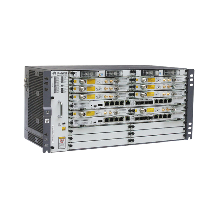
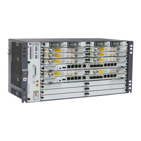
Huawei OptiX RTN 980 User manual

HUAWEI TECHNOLOGIES CO., LTD.
OptiX RTN 980 Radio TransmissionSystemV100
IDUQuick InstallationGuidefor OutdoorCabinets
(APM30H&TMC11H Cabinets)
Issue: 01
Date:2018-10-30

Huawei Technologies Co., Ltd.
Address: Huawei Industrial Base
Bantian, Longgang
Shenzhen 518129
People's Republic of China
Website: http://www.huawei.com
Email: support@huawei.com
No part of this document may be reproduced or transmitted in any form or by any means without prior
written consent of Huawei Technologies Co., Ltd.
Copyright © Huawei TechnologiesCo.,Ltd. 2018. All rights reserved.
Trademarksand Permissions
and other Huawei trademarks are trademarks of Huawei Technologies Co., Ltd.
All other trademarks and trade names mentioned in this document are the property of their respective
holders.
Notice
The purchased products, services and features are stipulated by the contract made between Huawei and
the customer. All or part of the products, services and features described in this document may not be
within the purchase scope or the usage scope. Unless otherwise specified in the contract, all statements,
information, and recommendations in this document are provided "AS IS" without warranties, guarantees
or representations of any kind, either express or implied.
The information in this document is subject to change without notice. Every effort has been made in the
preparation of this document to ensure accuracy of the contents, but all statements, information, and
recommendations in this document do not constitutea warranty of any kind, express or implied.

1
Precautions
Following All Safety Precautions
•Before anyoperations,readtheinstructions andprecautionsinthis documentcarefullyto minimize the
possibilityof accidents.
•The Danger,Caution,andNote items inthis documentdo notcover allthe safety precautions thatmustbe
observed.They provide onlythe genericsafetyprecautions foroperations.
•When operating Huaweiproducts andequipment,youmustcomplywith safetyprecautions andspecialsafety
instructions relevanttothe correspondingequipmentprovided by Huawei.The safetyprecautions inthis
documentare relevant onlyto Huawei products.Huaweiis notliable forany consequencethatresults from
violation of universal regulationsforsafetyoperations andsafetycodes ondesign,production,andequipment
use.
Complying with Local Safety Regulations
When operatingthe productor equipment,complywithlocalsafetyregulations.
Qualified Personnel Only
Installationandmaintenancepersonnelmustbetrainedtoperform operations correctlyand safely.
Personnel Safety
•The high-voltage powersupplyprovides powerfor running the system.Avoid direct contact with the high-voltage
powersupplyor contact throughdampobjects.Failuretodo socauses seriousinjuryordeath.
•Non-standardandincorrectoperationsonthehigh-voltage powersupplymayresultin fire and electricshock.
•Do not perform operations onhigh-voltageandACpowersupplyfacilities oron a tower or mastin the caseof
thunderstorm.Failuretodo socauses serious injuryor death.
•Groundthe device before poweringiton. Failureto do socauses damagetothedevice or personalinjury.
•Poweroff the device before performing operationsonthepowersupplyfacilities.
•Highpowerradio-frequencysignalsareharmful tothe humanbody.Ensurethat the transmitterantennas are
muted beforeinstalling ormaintaining an antenna on atoweror mastthat holds a largenumberoftransmitter
antennas.
•Do not stand closeto,or look intothe opticalfiber outlet withouteye protectionwhenhandlingopticalfibers.
•Take preventive measures whendrillingholes.Otherwise,dustmayhurt your eyes or you mayinhalethe dust.
•Poweroff the batteries beforeconnectingthecables tothe batteries.Failureto do socauses personal injury.
•When working at heights,be cautious aboutfalling objects.
Device Safety
•Checkthe electricalconnectionof the device beforeoperationandensure thatthe device is securelygrounded.
•The staticelectricity dischargedfrom thehumanbodymaydamage theelectrostaticsensitivecomponents,such
as large-scaleintegratedcircuits(LSIs),onthe circuitboard. Wear anESD wriststrapor ESD gloves when
handlingacircuitboard.
•When operatingbatteries,takepropermeasures topreventshortcircuits in the batteries andelectrolytespillor
loss.Theelectrolyte mayerode metal and boards,oreven causerustof the equipmentorshortcircuits inthe
boards.

2
Do not holda boardwithouthand protection.Wear an ESD wriststripor ESD gloves beforehandlinga board.
•Insertfiller panels intovacant slots onanNE to prevent foreignmatters from getting intothe NE,
whichmayresultin faults on the NE.
•Boards arefragile andvaluable. When handling orplacing aboard, exercisecaution andput it into a
dedicatedpackingbox.
HoldingaboardwithouthandprotectionWearingESD gloves Wearingan ESD strip
Holdthe front panelof a board with hands.
Instructions and Precautions for Handling Boards
CAUTION
CAUTION
CAUTION

3
1
1
2
2
3
3
1
1
2
2
3
3
Precautions for Handling the ToggleLever Switch
Turn the togglelever switchonlyafter
gentlypulling it out.
•Position and description of the toggle lever switch
I : ON
O: OFF
•Turning on the switch
•Turning off the switch
Pull the switchout gently. Turn the switch. Releasethe switch.
CAUTION
A dual-channelIFboard does not
have a togglelever switch.
NOTE

4
Tools for Installation
Networkcabletester
Coax stripper
Long measuring tape Phillips screwdriver Flat-head screwdriver AdjustableWrench
Level
COAX crimping tool
Socket wrench Torque wrench Hex key Wire clippers
Wire stripper RJ45 crimping tool Diagonal pliers Cold press pliers Needle-nose pliers
Combination pliersBayonetwrench
Utility knife Claw hammer
Hammer drill Marker
Ladder Electric iron
Antistatic gloves
Heat gun
Multimeter
ESD gloves
Binding strap Insulation tape
ESD wriststrap Impact tool
File
Vacuumcleaner

FrontView
a
5
Introduction to the Equipment
1Introduction to the RTN 980
Basedon different board configurations,thepositions ofthe actualIDU ports maybe different from the
positions shown inthe figure.
ObliqueView
bSideView
c

6
2Introduction to the APM30H/TMC11H Cabinet
FrontViewof theAPM30HCabinet
a
Technical Specifications
•Dimensions(mm):700(H)x 600 (W) x 480(D)
•Ambienttemperature:-40°C to +50°C
•Sunshineradiation:1120±10%W/m2
LeftViewof the APM30HCabinet
bRight Viewof theAPM30HCabinet
c
The exterior of the TMC11H cabinetis the
same as the exterior of the APM30H cabinet.
NOTE

7
HPMI board*
About the InternalStructureoftheAPM30HandTMC11HCabinets
d
Fan assembly(internalcirculating)* CMUA board PSU module
EPS frame PMU module
Fan assembly(internal circulating)* CUMA board DCDU-03module
•Internal Structure of the APM30H Cabinet (AC Power Supply)
•Internal Structure of the TMC11H Cabinet (DC Power Supply)
Cabledistributionbox
Cabledistribution box
*: In cabinets of Ver. D, HPMI boards are not supported, and internal circulation fan boards are replaced byFAN 02D boards.
NOTE

8
Installation Scenarios of the Cabinets
1Installation Scenarios of the APM30H or TMC11H Cabinet
Requirementsfor the InstallationDimensionsandSpaceof the Cabinet
(Unit: mm)
a
InstallationScenarios
b
600 600 600
480
> 800
> 300
> 60
> 300
40 40
Maximum
120°
Cabinet Cabinet Cabinet
•The data showninthefigure is not for the concretepad.
•The recommended distance between the cabinets is 40mm and themaximum distance between the cabinets is 150mm.
•If the noisereduction module(NRM)is required,the distancebetweenthecabinets is 150mm.
•Installing the APM30H cabinet on the base
APM30H
IBBS200D/T
battery
cabinet
IBBS200D/T
Base
The installationscenarios oftheTMC11H cabinetare the same
as those of the APM30H cabinet.
•Installing the APM30H cabinetin a stacked manner
NOTE
NOTE

9
2Installing the Cabinets
Installingthe Base
a
52-60mm
90°
Φ16
Cast a concrete pad.
Mark the anchor points for the base.
Drill the holes by using a hammer drill.
Concretepad
The heightof the concrete pad mustmeettheheat-dissipation andwaterproofingrequirementsofthe
cabinet.The concrete padmustbe200mm higherthan the ground,andthe horizontal errormustbeless
than 5 mm whenthe padis cast.
Do not usethe baseas a positioningtoolwhendrilling.Otherwise,thepainton the basemaybe scratched.
Concretepad
Unit: mm
CAUTION

10
Install the expansion bolt assembly.
Springwasher12
M12x60 bolt
Expansiontube
Rubber
mallet
Removethe springwasher,
flat washer,and bolt.
Flat washer12
Remove the front cover of the base.
Adjust the base level.
Tighten the bolts by using a
torque wrench.
Position the base, and then screw the bolt
with the spring washer and flat washer.
Adjust the baselevelby addingcertainpads tothe bolts
betweenthe baseandtheconcrete pad.

11
Remove the baffle plates from both sides
of the base (by removing the plate on the
left side as an example).
Remove the baffle pieces from the back
of the base.
All the threecable holes onthe basecan be usedfor
cablelayout, dependingon theactualrequirements.
10
MovingtheCabinetontothe Base
b
Install the lifting lugs. Tie the ropes.
Store the plasticscrews properly.
Maximum 90°
Plastic
screw
Lifting lug
Move the cabinet onto the base. Remove the ropes and install the plastic screws.
Before installingthe plasticscrews,cleantheinstallationholesto ensurethatthey are free of metal
shavings.
Select a propermethod tomove the cabinetas required.The crane is here usedas an example.
NOTE
NOTE
CAUTION
CAUTION

12
SecuringtheCabinetontotheBase
c
The IBBS200D batterycabinet is considered as an example in the installation. When installing the APM30H,
TMC11H, or IBBS200T cabinet,usethe samemethod.
Waterproof rubber pad
Gasketwith an oblonghole
Gasketwith an
oblonghole
M12x30 (x4)
Stacking the Two Cabinets(Optional)
d
Remove the four plastic screws
from the top of the lower cabinet.
M12x30 bolt (x4)
Remove the two cover plates
from the top of the lower cabinet. Remove the four rubber
caps from the bottom of
the upper cabinet.
Stack the cabinets, and then
secure the cabinets with the
four bolts.
Rubbercap(x4)
To ensurethewaterproof
performance ofthe cabinet,
retainthe cover plates
properlyfor the roundhole
of the cabinet.
Cover plate
Gasketwith an oblonghole
Gasketwith an
oblonghole
NOTE
CAUTION

M
D
1
M
D
1
13
Installation Scenarios of the Transmission Equipment
1Dedicated Outdoor Installation
Installingthe RTN980in theAPM30HCabinet
a
Installingthe RTN980in the TMC11HCabinet
b
Heater
RTN 980 5U
1U
7U
5U
11U
Heater
RTN 980
SLPU
DCDU-03
Fan unit
A 1 U spaceneeds to be
reservedbetweenthe RTN 980
andthe heater.
NOTE
A 1 U spaceneeds to be
reservedbetweenthe RTN 980
andthe heater.
NOTE
Powersupplysystem
Fan unit

M
D
1
14
2CabinetSharing-InstallingtheRTN 980in the TMC11HCabinet
Heater
RTN 980
BBU
DCDU-03 •A 1 U spaceneeds tobe reserved
betweenthe RTN 980andthe heater.
•If the RTN 980 and wirelss transmission
equipmentneedtobeinstalledinone
cabinet,the cabinetmustbe a TMC11H
cabinet.
Installing the Assemblies
1Installing the RTN 980
Floatingnut
Installation
hole
Removethe guiderail,if any, from the installationposition.
Fixing the floating nuts.
InstallingtheRTN
980.
NOTE
NOTE

15
2Installing the SLPU
Specificationsofthe SLPU
a
•The SLPU is anoptionaldevice. It is requiredif servicecables are routedout of cabinets.
•You canselectthe port type of a boardthat correspondstothe SLPU based onthe port type of the RTN 980.
•The UELP is a general-purpose surge protectionunitforE1 or T1 services.A UELP is used forsurge
protectionof four E1 or T1 signals.
•The UFLP is a general-purpose surgeprotection unitforFE or GE services.A UFLP can be usedforsurge
protectionof two FE or GE signals.
Installingthe SLPU
b
The SLPU is generallyequipped withtwo UELP boards andoneUFLPboard. If morethan eightE1
signals aretransmitted,oneortwo extra UELPboards need to bedeliveredwith the equipmentandneed
to be installedinthevacant slots ofthe equipmentonsite.Ifmorethan 12 E1 signals aretransmitted,the
UFLP boardneeds to be replacedwiththe UELP board.The removedUFLP boardneeds to be returned
to the localrepresentativeoffice of Huawei.
NOTE
NOTE
OUTSIDE
UELP
INSIDE
OUTSIDE
UELP
INSIDE
FE0
OUTSIDE
UFLP
INSIDE
FE1 FE0 FE1
UELP UFLP
UFLPc FE/GE0 FE/GE1 FE/GE0 FE/GE1

16
3Installing the Heater(Optional)
Installthe heater.
•When the temperatureinsidethe cabinetis lowerthan0°C, the heaterstarts working.When the
temperature insidethe cabinetis higherthan15°C,the heaterstops working.
•The maximum powerofthe heaterduringthe heatingprocess is 300 W.
The heateris preferablyinstalled inthe bottom
1U spaceofthe cabinet. If both the SOU andthe heater areinstalledinthe
cabinet,the heater is installedabovetheSOU.
Installthe powercablefor the heater.
NOTE
powercable
for the
heater.
AC inputpower
cable
AC input
powercable

17
1Installing the PGND Cables
Installingthe PGND Cablesforthe Cabinet
a
•When installingthePGNDcables intheAPM30H cabinet,usethe same
method.
•The groundcables and signalcables mustbeboundseparatelyormustbe
separatedfrom eachotherto minimizemutualinterference.
Installingthe PGND Cablesforthe Equipment
b
Installing and Routing the Cables
WARNING
NOTE
MD1
M
D
1
FE0
OUTSIDE
UFLP
INSID E
FE1FE0FE1
Groundbar
PGND cableof the
SLPU
PGND cableof the
RTN 980
Ground bar

19
1
1
DC power
box cover
Removethe cover of
the DC powerbox.
2
2
NEG(-)
RTN(+)
Installthe inputpowercable.
3Put back the cover of
the DC powerbox.
Installingthe InputPower Cableforthe TMC11HCabinet
a
1
1
2
2
33
Installingthe PowerCablesfor the RTN980 in the TMC11HCabinet
b
18
NOTE
MD1
M
D
1
FE0
OUTSIDE
UFLP
INSID E
FE1FE0FE1
1
A
B
C
2Installing and Routing the Power Cables –DC Power Supply
For a cabinetof Ver. D, usepoweroutput terminals withthe fusecapacity
of 30 A to supplypowerto RTN 980.
You canselectfrom DC poweroutput terminals LOAD6,LOAD7, and
LOAD8. For informationaboutassemblingtheeasypowerreceptacle
(pressfittype) connector,seethe "Appendixes."
Other manuals for OptiX RTN 980
1
Table of contents
Other Huawei Microphone System manuals

Huawei
Huawei OptiX RTN 950 User manual

Huawei
Huawei OptiX RTN 320F User manual

Huawei
Huawei OptiX RTN 600 Technical specifications

Huawei
Huawei OptiX RTN 980 User manual

Huawei
Huawei OptiX OSN 2500 User manual

Huawei
Huawei RTN 360 V100 User manual

Huawei
Huawei RTN XMC ODU Technical specifications

Huawei
Huawei OptiX OSN 550 User manual

Huawei
Huawei OptiX RTN 980L V100 User manual

Huawei
Huawei OptiX RTN 905 User manual