manuals.online logo
Brands
  1. Home
  2. •
  3. Brands
  4. •
  5. Huawei
  6. •
  7. Network Hardware
  8. •
  9. Huawei BBU3900 User manual

Huawei BBU3900 User manual

HUAWEI TECHNOLOGIES Co., Ltd.
BBU3900 V300R008
Installation Guide
Issue: 08
Part Number: 31504606
Date: 2009-04-20
1
Contents
1. Installing the BBU in the APM30
2. Installing the BBU in the APM30H
3. Installing the BBU in the 19-Inch Rack
4. Installing the BBU in the TMC
5. Installing the BBU in the PS4890 Cabinet
6. Installing the BBU in the RRU3004 Rack
7. Installing the BBU on the Wall
8. Reference
9. Changes in the BBU3900 Installation Guide
7
13
15
17
20
23
27
31
40
Copyright © Huawei Technologies Co., Ltd. 2009. All rights reserved.
2
Safety Information
Following All Safety Precautions
Before any operation, read the instructions and precautions in this document carefully to minimize the possibility
of accidents.
The Danger, Caution, and Note items in the documents do not cover all the safety precautions that must be
followed. They only provide the generic safety precautions for operations.
When operating Huawei products and equipment, you must comply with safety precautions and special safety
instructions related to corresponding equipment provided by Huawei. The safety precautions in the document
are related to only Huawei products. Huawei is not liable for any consequence that results from the violation of
universal regulations for safety operations and safety codes on design, production, and equipment use.
Complying with the Local Safety Regulations
When operating the device, comply with the local safety regulations. The safety precautions provided in the
documents are supplementary. You must comply with the local safety regulations.
Qualified Personnel Only
The personnel in charge of installation and maintenance must be trained and master the correct operating
methods and safety precautions before beginning work.
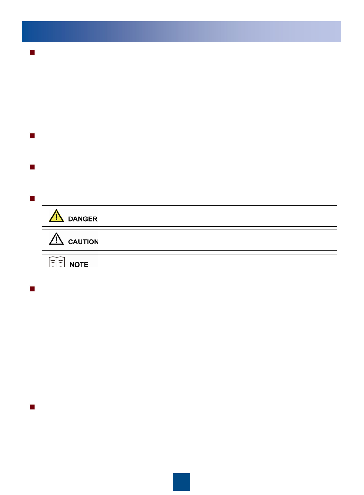
Symbols
Safety of Personnel
The high voltage power supply provides power for running the system. Direct contact with the high voltage
power supply or contact through damp objects may result in fatal danger.
Non-standard and improper high voltage operations may result in fire and electric shock.
In a thunderstorm, do not perform operations on high voltage and AC power supply facilities or on a steel
tower and mast.
Ground the device before powering on the device. Otherwise, the personnel and device are in danger.
Power off the device before performing operations on the power supply equipment.
High power radio-frequency signals are harmful to human body. Before installing or maintaining an antenna
on a steel tower or mast with a large number of transmitter antennas, the operator should coordinate with all
parties to ensure that the transmitter antennas are shut down.
When handling optical fibers, do not stand close to, or look into the optical fiber outlet with unaided eyes.
Protect yourself when drilling holes. Flying dust may hurt your eyes or you may inhale the dust.
Power off the batteries before connecting the cables to the batteries. Otherwise, casualties may occur.
When working at a height, be cautious about falling objects.
Device Safety
Check the electrical connection of the device before operation and ensure that the device is reliably grounded.
The static electricity generated by the human body may damage the electrostatic sensitive components on the
circuit board, such as the large-scale integrated circuit (LIC). Wear an ESD wrist
strap or ESD gloves when performing the operation.
When working on batteries, take measures to prevent short circuits in the batteries and electrolyte spill/loss.
The electrolyte may erode metal and boards, or even cause rust of the equipment or short circuits in the boards.
This symbol indicates that casualty or serious accident may occur if you ignore
the safety instruction.
This symbol indicates that serious or major injury may occur if you ignore the
safety instruction.
This symbol indicates that the operation may be easier if you pay attention to the
safety instruction.
3
Installation Tools
Long measuring tape Cross screwdrivers (M3~M6) Straight screwdrivers (M3~M6)
Adjustable wrench Socket wrench Percussion drill
ESD wrist strap Vacuum cleaner Cable peeler
Torque wrench Marking pen Level bar
Claw hammer RJ-45 crimping pliers Multimeter
Power cable crimping pliers Wire cutter ESD gloves
4
In the APM30/APM30H
On the wall
In the 19-inch rack
Installation Scenarios
5
In the RRU3004 rack
In the PS4890 cabinet
In the TMC cabinet
Installation Scenarios
6
Installing the cabinet
Start
Installing the BBU case
Installing the BBU cables
Powering on the BBU
End
Installing the cables of
cabinet
Installing the RRU module
Installing the RRU cables
Powering on the RRU
Installing the PGND
cable(BBU on the wall)
Installing the power cable
Installing the CPRI optical
cable
Installing the E1 cable or FE
cable
Installing the monitoring
signal cable(optional)
Installing the alarm
cable(optional)
Installing the E1 or FE surge
protection transfer
cable(optional)
Installation Procedure
7
Installing the BBU Case
a
Installing the BBU Cables
b
External power supply
External alarm device
Monitoring signal
cable
Alarm cable
E1cable
CPRI signal cable
E1 transfer cable
Power cable
Cable connections of the BBU
External monitoring device
Installing the BBU in the APM30
BBU
M6 bolt
PDU
1. Install the mounting ears at both sides of
the BBU reversely.
2. Slide the BBU case into the cabinet.
3. Check the DIP switches (see appendix).
FE cable
FE transfer cable
1、The FE cable is used for the IP transmission.
2、The E1 cable is used for the HDLC transmission.
8
Installing the BBU in the APM30
Winding pipe
Installing the BBU Cables
b
2. Install the CPRI optical cable. Connect one end of the optical cable to the CPRI0,
CPRI1, or CPRI2 port on the GTMU panel of the BBU and the other end to the CPRI_W
port on the RRU.
The TX port on the BBU is connected to the RX port on the RRU.
The RX port on the BBU is connected to the TX port on the RRU.
Connect the OT terminal of the power cable to the LOAD3
terminal of the PDU, and then fix the 3V3 connector of the
power cable to the PWR port on the BBU.
1. Install power cable.
The power cable is to be made
depending on field requirements.
Optical module
Puller
a. Insert the optical module into the CPRI0,
CPRI1, or CPRI2 port, and then turn
outwards the puller on the optical
module.
b. Insert one end of the CPRI optical cable
into the optical module, and then lead
the CPRI optical cable out of the
cabinet along the right side of the
cabinet.
c. Wrap the fiber tail with the winding pipe.
LOAD3
NEG(-)
RNT(+)
PWR
9
Installing the BBU in the APM30
b
4.3. Strip the jacket off the E1 cable near the grounding point at the lower right corner of
the cabinet to expose the shielding layer
4.4. Thread the E1 cable through the grounding clip. Then, tighten the screw on the
grounding clip to make the shielding layer of the E1 cable in full contact with the
grounding clip. Finally, connect the PGND cable on the grounding clip to the grounding
bolt of the APM30.
4.2. Fix the DB26 connector of the E1 cable to the OUTSIDE port on the UELP.
3. Install the E1 transfer cable.
4. Install the E1 cable.
E1 transfer cable
4.1. Cabling the E1 cable.
E1cable
Shielding layer of
the E1 cable
(25mm)
Ensure that both ends of the E1 cable are disconnected. Then, weld connectors to
the bare wires at one end of the E1 cable all at once.
Fix the DB25 connector of the E1 transfer cable to the INSIDE port on the UELP
and the DB26 connector to the E1/T1 port on the GTMU.
Grounding
clip
Installing the BBU Cables
10
b
FE transfer cable FE cable
(25mm)
Shielding
layer of
the FE
cable
Connect one end of the FE transfer cable to the FE0 port
near the INSIDE label on the UFLP and the other end to the
FE0 port on the GTMU.
5. Install the FE transfer cable (FE transmission mode).
6. Install the FE cable (FE transmission).
6.1. Connect one end of the FE cable to the FE0 port near the
OUTSIDE label on the UFLP. Then, lead the other end out of
the cabinet along the right side of the cabinet.
6.2. Thread the FE cable through the grounding clip. Then,
tighten the screw on the grounding clip to make the shielding
layer of the FE cable in full contact with the grounding clip.
Finally, connect the PGND cable on the grounding clip to the
grounding bolt of the APM30.
Installing the BBU Cables
Installing the BBU in the APM30
7. Install the monitoring signal cable between the APMI and the BBU.
7.1. Fix the RJ45 connector at one end of the cable to the MON1 port on the UPEU.
7.2. Cut off the RJ45 connector at the other end of the cable on site, and then connect the four exposed wires to the
RX+, RX-, TX+, and TX- ports on the APMI.
11
8. Install the EMUA monitoring signal cable. (The EMUA is configured if
there are external dry contacts or analog detection is required.)
8.1. If the MON0 port on the BBU is available, fix the RJ45 connector of the EMUA
monitoring signal cable to the MON0 port on the UPEU and the DB9 connector to the
corresponding port on the EMUA.
8.2. If the MON0 port on the BBU is unavailable, cut off the RJ45 connector of the EMUA
monitoring signal cable, and then connect the four exposed wires to the RX+, RX-, TX+,
and TX- ports on the APMI. For the pin assignment, see Page 38 EMUA monitoring
signal cable. Fix the DB9 connector to the corresponding port on the EMUA.
Installing the BBU Cables
b
Installing the BBU in the APM30
MON 0
12
9. Install the alarm cable. Connect one end of the alarm cable to the EXT-
ALM port on the UPEU and the other end to the corresponding alarm device.
Checking the Power-On Status of the BBU
c
Installing the BBU Cables
b
Installing the BBU in the APM30
The normal status of LED on the
WMPT is as follows:
• RUN LED: 1s ON, 1s OFF
(blinking at 0.5 Hz)
• ALM LED: OFF
•ACTLED:ON
The normal status of LED on the
UPEU is as follows:
• RUN LED: ON
The normal status of LED on the
UBFAis as follows:
• STATE LED: Green
1s ON, 1s OFF (blinking at 0.5 Hz)
The normal status of LED on the
WBBP is as follows:
• RUN LED: 1s ON, 1s OFF
(blinking at 0.5 Hz)
• ALM LED: OFF
a
Powering on the BBU3900
Start
End
Powering off the
BBU3900
Clearing the fault
Checking whether all LEDs on the
BBU are normal?
Yes
No
a
13
Installing the BBU in the APM30H
Installation PositionNo.
One end is connected to... The other end is connected to...
1
2
3
4Monitoring signal
cable COM IN port on the HEUA MON1 port on the BBU
5CPRI optical cable CPRI port on the BBU CPRI port on the RRU
BBU power cable LOAD3 terminal of the PDU PWR port on the BBU
E1 transfer cable E1/T1 port on the GTMU INSIDE port on the UELP
E1 cable OUTSIDE port on the UELP GEHUB or HUBBTS
Cable
aBBU Cable Connections
The procedure for installing the BBU case in the APM30H is the same as that in the APM30.
For details, see pages 7–12. The following figure shows the cable connections of the BBU.
Page 14 shows how to install the monitoring signal cable between the HEUA and the BBU
in the APM30H.
14
Installing the BBU in the APM30H
bInstalling the Monitoring Signal Cable between the HEUA and the BBU
MON1
COM IN
UPEU on the
BBU
HEUA
15
bInstalling the DCDU-03B
c
When the BBU3900 is installed in the 19-inch cabinet, no space is required on the left and
right of the BBU3900.
Installing the BBU in the 19-Inch Rack
Space Requirements (Unit: mm)
a
Installing the BBU Case
16
(1) BBU power cable (2) Monitoring signal cable for
the DCDU-03B (3) PGND cable (4) CPRI optical cable
(5) E1 transfer cable (6) E1 cable (7) BBU alarm cable (8) RRU power cable
(9) External power cable
Installing the BBU Cables
d
Installing the BBU in the 19-Inch Rack
②Connect the BBU
power cable to the
LOAD8 terminal on
the DCDU-03B.
⑧Connect the RRU
power cable to one of
the LOAD0 to
LOAD5 terminals on
the DCDU-03B.
17
Installing the BBU in the TMC
Installing the DCDU-03B
a
Slide the DCDU-03B into the TMC. Then, tighten the four M6 screws.
Installing the BBU Case
b
Slide the BBU into the TMC. Then, tighten the four M6 screws.
18
Installing the BBU in the TMC
Installing the BBU Cables
c
DCDU-03B input
power cable
1. For details on how to install the TMC alarm cable, see Page 19.
2. The DCDU-03B input power cable is connected to the external DC power supply system.
3. For cable connections of the BBU, see Page 7.
19
Installing the BBU in the TMC
Checking the Power-On Status of the BBU
d
Check the power-on status of the BBU. For details, see Page 12.
Installing the BBU Cables
c
Procedure for installing
the TMC alarm cable: APMI panel Door status
sensor
b. Connect the two bare
terminals X1.4 (blue) and
X1.5 (white) to the alarm
wiring terminals of the
door status sensor.
c. Connect the two bare
terminals X1.1 (white)
and X1.2 (orange) to the
OUT1+ and OUT1-
alarm wiring terminals on
the APMI.
d. Connect the two bare
terminals X1.3 (white)
and X1.6 (green) to the
alarm wiring terminals of
the DCDU.
a. Fix the RJ45 connector
at one end of the alarm
cable to the EXT_ALM1
port on the BBU.

Other manuals for BBU3900

5

Other Huawei Network Hardware manuals

Huawei CR52-10GE User manual

Huawei

Huawei CR52-10GE User manual

Huawei OptiX OSN 8800 Guide

Huawei

Huawei OptiX OSN 8800 Guide

Huawei OptiXstar P802E User manual

Huawei

Huawei OptiXstar P802E User manual

Huawei EchoLife HG8247H Operator's manual

Huawei

Huawei EchoLife HG8247H Operator's manual

Huawei V600R019C00 Technical specifications

Huawei

Huawei V600R019C00 Technical specifications

Huawei EG8040F5 User manual

Huawei

Huawei EG8040F5 User manual

Huawei NetEngine-8000-M8 User manual

Huawei

Huawei NetEngine-8000-M8 User manual

Huawei FIC-1E1 User manual

Huawei

Huawei FIC-1E1 User manual

Huawei BBU3806 User manual

Huawei

Huawei BBU3806 User manual

Huawei PDU8000 Series User manual

Huawei

Huawei PDU8000 Series User manual

Huawei RRU3942 User manual

Huawei

Huawei RRU3942 User manual

Huawei RRU3203 User manual

Huawei

Huawei RRU3203 User manual

Huawei SmartLi User manual

Huawei

Huawei SmartLi User manual

Huawei OceanStor S5600 User manual

Huawei

Huawei OceanStor S5600 User manual

Huawei OptiXstar V183 User manual

Huawei

Huawei OptiXstar V183 User manual

Huawei FTK01 User manual

Huawei

Huawei FTK01 User manual

Huawei Airbridge DBS3900 Guide

Huawei

Huawei Airbridge DBS3900 Guide

Huawei CR52-10GE User manual

Huawei

Huawei CR52-10GE User manual

Huawei CR52K-10GE-SFP User manual

Huawei

Huawei CR52K-10GE-SFP User manual

Huawei FusionModule1000A20 User manual

Huawei

Huawei FusionModule1000A20 User manual

Huawei BTS3900 GSM User manual

Huawei

Huawei BTS3900 GSM User manual

Huawei EMUA Series User manual

Huawei

Huawei EMUA Series User manual

Huawei RT-NE20E-NPU User manual

Huawei

Huawei RT-NE20E-NPU User manual

Huawei RT-16ASE User manual

Huawei

Huawei RT-16ASE User manual

Popular Network Hardware manuals by other brands

Novus NVS-3308SP user manual

Novus

Novus NVS-3308SP user manual

ADTRAN DS3 MX Job aid

ADTRAN

ADTRAN DS3 MX Job aid

Qualys GUARD quick start guide

Qualys

Qualys GUARD quick start guide

Teledyne GV 400 installation manual

Teledyne

Teledyne GV 400 installation manual

Emerson ControlWave Remote Ethernet I/O Product data

Emerson

Emerson ControlWave Remote Ethernet I/O Product data

Telebyte 458-LM-E8-36 manual

Telebyte

Telebyte 458-LM-E8-36 manual

VMware ANYWHEREUSB - TECHNICAL USB Using

VMware

VMware ANYWHEREUSB - TECHNICAL USB Using

Idis DR-4516P installation manual

Idis

Idis DR-4516P installation manual

CP Plus CP-VTA-M1143 user manual

CP Plus

CP Plus CP-VTA-M1143 user manual

PairGain FLC-703 manual

PairGain

PairGain FLC-703 manual

Digitus DN-15028 Quick installation guide

Digitus

Digitus DN-15028 Quick installation guide

TransLite TL-9802 manual

TransLite

TransLite TL-9802 manual

Ontech GSM 9035 quick start guide

Ontech

Ontech GSM 9035 quick start guide

3Com 3C17203 - SuperStack 3 Switch 4400 Getting started guide

3Com

3Com 3C17203 - SuperStack 3 Switch 4400 Getting started guide

Genie W3500S user manual

Genie

Genie W3500S user manual

MikroTik G16-a-LHGR kit Series quick guide

MikroTik

MikroTik G16-a-LHGR kit Series quick guide

FS ONU2110-8GP quick start guide

FS

FS ONU2110-8GP quick start guide

Quantum 1U Getting started guide

Quantum

Quantum 1U Getting started guide

manuals.online logo
manuals.online logoBrands
  • About & Mission
  • Contact us
  • Privacy Policy
  • Terms and Conditions

Copyright 2025 Manuals.Online. All Rights Reserved.