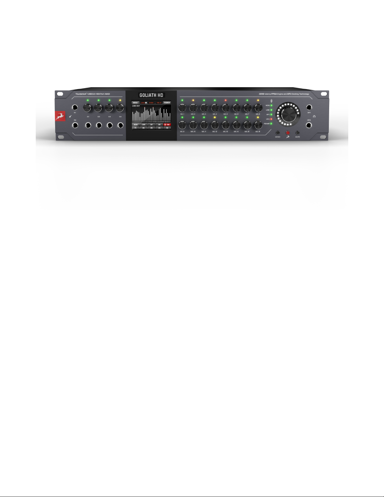
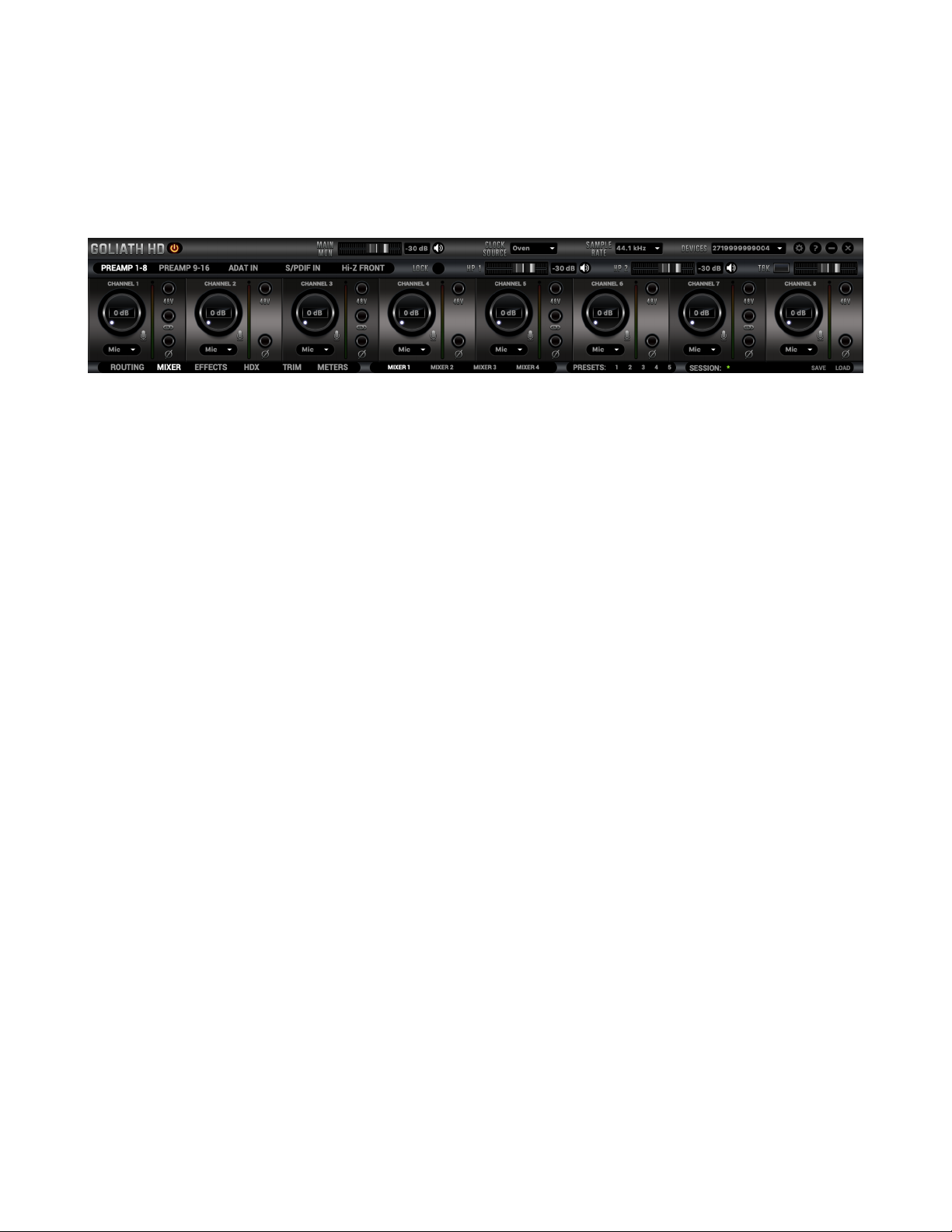
Antelope Goliath HD Gen. 3 User manual

Goliath HD | Gen. 3
User Manual
Contents
1. Safety Notes
2. Quick Start
3. Front Panel xplained
4. Rear Panel xplained
5. Touchscreen xplained
6. Software Control Panel
6.1 Main View and Routing Tab
6.2. Mixer Tab
6.3 AuraVerb
6.4 ffects Tab
6.5 Meters Tab
6.6 HDX Settings Tab
6.7 Trim Tab
6.8 Settings Tab
7. Troubleshooting
1. Safety Notes
To reduce the risk of electrical shocks, fire, and related hazards:
•Do not remove screws, cover, or cabinet. There are no user serviceable parts inside.
Refer servicing to qualified service personnel.
•Do not expose this device to rain, moisture or spillover of liquid of any kind.
•Should any form of liquid or a foreign object enter the device, do not use it. Switch off the
device and then unplug it from the power source. Do not operate the device again until the
foreign object is removed or the liquid has completely dried and its residues fully cleaned up. If
in doubt, please consult the manufacturer.
•Do not handle the power cables with wet hands!
•Make sure the device is switched off when plugging/unplugging it to/from the power source.
•Avoid placing things on the cabinet or using the device in a narrow and poorly ventilated place
which could affect its operation or the operation of other closely located components.
•If anything goes wrong, turn off the device first and then unplug the power. Do not attempt to
repair the device yourself. Consult authorized service personnel or your dealer instead.
•Do not install near any heat sources such as radiators, stoves, or other apparatus (including
amplifiers) that produce heat.

•Do not use harsh chemicals to clean your unit. Clean only with specialized cleaners for
electronics equipment.
•Connect all your devices before powering your unit.
•This unit is connected via its power cord to the mains safety earth.
•Never operate the unit without this earth connection.
•DC power supply cable should be routed so that it is not likely to be walked on or squeezed by
items placed upon or against it.
•To completely turn off the device, unplug the power cable first from the outlet and then from
the rear panel of the unit.
•Both occasional and continued exposure to high sound pressure levels can cause permanent ear
damage via headphones and monitors.
•Your unit should always be unracked when traveling or in a flight case.
•The device is designed to operate in a temperate environment, with a correct Operating
Temperature of 0-50° C, 32-122° F.
2. Quick Start
Once the Goliath HD | Gen. 3 has been connected to an AC power source:
1. Connect the HDX, USB 3.0 or Thunderbolt™ cable to the corresponding ports on your device and
computer.
Note: The HDX ports are disabled by default and can be enabled with an upgrade. Visit the Goliath HD
| Gen. 3 product page to learn more.
2. Download and install the Antelope Audio Launcher and Unified Driver from the Downloads
section on the Goliath HD | Gen. 3 website.
3. Start the Antelope Audio Launcher. The application will automatically update itself and proceed to
download and install the Goliath HD | Gen. 3 software Control Panel.
4. Open the Control Panel from inside the Launcher and follow the device activation procedure.
5. Connect your analog and digital gear of choice to Goliath HD | Gen. 3.
6. Open your preferred DAW and ensure the device is selected as your main input and output device.
Note: Make sure your Goliath HD | Gen. 3 has the most recent firmware installed. The Antelope
Launcher will inform you if a newer version is available

3. Front Panel Explained
1. ReA p Outputs
These outputs deliver instrument-level signal for use with guitar amplifiers and other gear suitable for
re-amping.
2. Hi-Z Instru ent Inputs
Hi-Z Inputs with dedicated gain control knobs, suitable for connecting high-impedance instruments
such as bass and guitar.
3. High-Resolution Touchscreen Display
Displays various information and provides control over device functionality.
4. Channel Gain Control Knobs / Input Selectors
To adjust a channel’s input signal level, turn the knob left/right. Levels can be adjusted in 1dB
increments. The peak indicator lights in response to the input signal level.
Press and hold the rotary knob to mute the corresponding channel.
To switch between input modes (Mic, Line, Hi-Z on inputs 1 – 4), press the rotary knob. Please ensure
that your choice matches the type of input signal.
5. Talkback ic
Press the Talkback button on the main display to activate the talkback microphone. It can be routed to
the chosen headphone and/or monitor outputs from the software Control Panel.
6. Main Rotary Knob with LED Ring
Press the knob to cycle through the Monitor, Line, Headphones and ReAmp outs’ volume levels. Turn
the knob to adjust them. The L D Ring shows the Volume Control or Mute status of the chosen output.

7. Mono Button
Changes the current output that is selected by the Main Rotary Control from Stereo to Mono.
8. Antelope Button
Press the Antelope button & Mono button to enter touchscreen calibration mode.
9. Mute Button
Mutes the output currently selected by the Main Rotary Control.
Note: Press and hold the Mono button + Mute button before powering on the device for Factory Reset.
10. Headphone Outputs
Two independently assignable headphone outputs, selectable and controllable via the main volume
control knob. The lights next to the outputs are illuminated to indicate which headphone output is
currently controlled.
4. Rear Panel Explained
11. Mains Power Connector
The I C connector supports a range between ~95-245V. This lets the device automatically
accommodate the mains voltage in each country.
12. Word Clock Input (also used for HDX Loop Sync)
BNC input used to accept Word Clock reference signal.
13. 10M Input
BNC Input Connector for receiving timing reference from an Atomic Clock, such as the Antelope
Audio 10M and 10MX. Useful for raising the oscillator accuracy even higher.

If the device is in Oven mode, connecting an Atomic Clock causes the “Oven” light to turn to “Atomic”
on the touchscreen. The atomic device becomes the primary timing reference, resulting in improved
sample accuracy, more detailed sound, and greater stability.
14. Word Clock Outputs (also used for HDX Loop Sync)
Two Word Clock Outputs on BNC connectors.
15. S/PDIF I/O
75 Ω S/PDIF inputs and outputs on RCA connectors. For use with compatible equipment.
16. ADAT Inputs and Outputs
2 Inputs & 2 Outputs with up to 8 channels per line.
17. AES/EBU I/O
D-SUB 25 connector with 4 ins and 4 outs. Compliant with the TASCAM standard.
18. MADI Inputs and Outputs
2 x MADI I/O Connectors providing 64 tracks input and 64 tracks output per connector.
19. Monitor Outputs
A stereo pair (2 x ¼ TRS) of balanced outputs to connect a pair of monitors.
20. Thunderbolt™ Port
For connecting the Goliath HD | Gen. 3 to a Thunderbolt™ port on a Mac or Windows computer with a
Thunderbolt™ cable (not included).
21. USB 3.0 Port
USB 3.0 connector for Windows & macOS computers.
22. HDX Ports
For connecting to an HD system. Cable not included.
23. Analog Line Outputs (top)
Four D-SUB 25 connectors for attaching breakout cables with 8 lines each.
24. Analog Line Inputs (botto )
Two D-SUB 25 connectors for attaching breakout cables with 8 lines each.
25. Analog Inserts
Two ¼” TRS analog inserts (L & R) for connecting analog gear, such as equalizers and compressors.
Placed just before the A/D conversion stage.
26. Mic/Line Inputs
16 mic/line inputs with Class-A microphone preamps. The first four are also Hi-Z instrument inputs.
5. Touchscreen Explained
The Goliath HD | Gen. 3 has a touchscreen on its front panel. You can access many of the device’s
functions from it.

Menu
Here you can adjust different parameters:
Co Interface
Choose the type of interface between your device and computer – HDX, USB or Thunderbolt™.
Screen Saver Style and Ti e
Changes how long it takes for the screensaver to appear, as well as the screensaver style.
SR Conversion
nables and disables the Sample Rate Converter for the S/PDIF Inputs.
Presets Saving
Stores the current settings in a preset.
Main Display
Tap it to select the meters currently being displayed.
Lock
Indicates whether the Goliath HD | Gen. 3 is locked to an incoming signal.
MON
nter the Monitor menu to adjust the Monitor volume level from the main Volume Knob.
LINE
nter the Line Out menu to adjust the output volume level.
HP
Cycle through the two Headphone Outputs and set their volume levels.
PREAMP Volu e
Cycle through the preamp inputs and set their volume levels.
CS
Shows the current Clock Source. It’s set to Oven by default. The selected source is displayed on the top
of the touchscreen. Tap to choose from the available clock sources.
SR
Select the device Sample Rate. Tap the SR button to see the available options. The current Sample Rate
will be shown on the top of the touchscreen.
Presets 1–5
Global Presets 1 - 5 save all device settings to one of the five preset slots. Buttons P1 to P5 let you
cycle between presets.
TBK
Set the Talkback volume level and output destination (HP1, HP2, Monitor Outs, etc.).

6. Software Control Panel
6.1. Main View and Routing Tab
The Universal Panel View is constantly present in the upper half of the Control Panel, enabling quick
access to the most important features.
Main view:
1. Power/Standby button
2. Main Monitor volume slider
3. Main Monitor Mute button
4. Clock Source
This menu lets you choose how the Goliath HD | Gen. 3 is to be synchronized:
•Select ‘Oven’ for internal sync
•Select WC (Word Clock) to sync to an external device through the Word Clock input
•Select any digital input (ADAT, MADI, S/PDIF, A S) to sync with incoming digital signals
•Select HDX / Thunderbolt™ / USB to sync through the corresponding interface.
5. Sa ple Rate select
Choose the device Sample Rate. Your choice of Clock Source and Sample Rate will automatically
determine the number of channels available in the Inputs & Outputs routing tab.
6. Lock Light
When your Goliath HD | Gen. 3 syncs to an external clock source, a “Pad Lock” symbol will be
displayed next to the clock source and you won’t be able to change presets as they do not store clock
source or sample rate information.
7. Devices
This menu lets you choose between Antelope Audio devices connected to your computer or on the
same network.
8. Settings
9. Info
10. Minimize & Close
11. PR AMP 1-8 / PR AMP 9-16 / ADAT IN / S/PDIF IN / INST FRONT Section
12. Talkback active button / Indicator light & Talkback volume fader
13. Headphone 1 volume slider
14. Headphone 2 volume slider

13. Mixers 1–4 Section
Switch between the four software mixers.
14. Presets 1–5 Section
Five preset slots let you store Control Panel setups for easy recall.
To save a new preset:
• Hold down Ctrl (PC) or Command (Mac) and click on the preset button
or
• Press Ctrl (PC) or Command (Mac) and press a number between 1 - 5 on your keyboard.
You can also reset the presets to factory settings or check device info.
15. Input Mode
Choose between Mic, Line and Hi-Z (inputs 1, 2, 3, 4 only) modes from the dropdown menu.
Note: please make sure your selection matches the input signal type.
16. Channel Gain
Adjustable in 1dB increments.
Note: Ctrl+Left-Click (Win) / Cmd+Left-Click (Mac) mutes the channel.
17. Peak Meter
18. 48V Phantom Power Switch (independently assignable)
19. Phase Reverse button
20. Stereo Link
21. Session Save / Load
Sessions (snapshots of the entire Control Panel) can be stored and recalled. This way, you can easily
save & load gain levels for each input and output; clock modes; driver settings; FX and AuraVerb
parameters; Mixer and Routing adjustments, as well as personalized window positions.

6.1.1 Routing Tab
1. Undo/Redo Routing; Save/Load Routing;
2. Alternate Matrix View
3. HOW TO Button
Launches your internet browser with a tutorial video.
Antelope Audio Routing Matrix Explained
The Antelope Audio Routing Matrix controls your analog and digital audio routing from your device’s
software Control Panel.
The Routing Matrix is row-based. ach row has its own unique color and represents a specific audio
channel with its predefined channel count.
The Matrix view is split in two main sections: From Section [Input Source] and To Section
[Destination]. You route audio between them by dragging and dropping number blocks.
Fro [Input Source] Section
Contains both physical inputs and software outputs. ach source has channel numbers and an unique
color highlight.

PREAMP
Your interface’s microphone preamp inputs are represented with PR AMP, followed by numbers
referring to each preamp input.
EMU MIC
Input signal with mic emulations applied. Suitable for recording dry and effected audio simultaneously.
Only for use with the Antelope Audio dge & Verge modeling microphones.
INSTRUMENT
These are the Goliath HD | Gen. 3’s four instrument (Hi-Z) inputs.
LINE IN
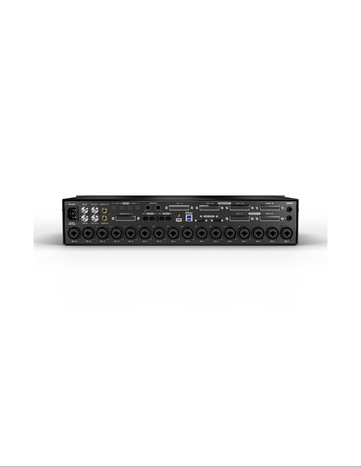
Line Level inputs are located on your audio interface via D-Sub 25 pin connectors (TASCAM
Standard Pin Layout). ach D-Sub connector has 8 mono channels. In the Routing Matrix, line inputs
are represented in the Line In row.
USB PLAY
When your interface is connected over USB, USB Play handles all computer audio (DAW, multimedia,
YouTube, etc.) This row lets you route computer audio, including audio coming from your DAW.
Depending on your product, you may have between 24/ 32 /64 USB Playback channels.
TB PLAY
When your interface is connected via Thunderbolt, TB Play handles all computer audio (DAW,
multimedia, YouTube, etc.) This row lets you route computer audio, including audio coming from your
DAW. Depending on your product, you may have between 32/64 TB Playback channels.
HDX PLAY
When your interface is connected via HDX, HDX Play handles all computer audio (DAW, multimedia,
YouTube, etc.) This row lets you route computer audio, including audio coming from your DAW.
MADI IN 1 & 2
Handles up to 128 input audio channels over MADI.
ADAT IN
Handles up to 16 ADAT Optical Audio Inputs via 2 ports of 8 channels each.
S/PDIF IN
Handles 2 channels of Stereo S/PDIF audio, coming over coaxial RCA cable.
AFX OUT
AFX (short for Antelope ffects) represents audio channels with FPGA effects processing applied. You
can route up to 16 Mono channels from the AFX Tab to your desired location.
Low Latency Mixer Outputs
MIX 1 L/R to MIX 4 L/R represent Stereo output signals coming from each of the Control Panel’s four
software mixers.
Talkback
Mono input from the integrated Talkback microphone.

To [Destination] Section
This section is meant to receive audio from the channels represented in the From [Input Source]
section. Note that some input channels are already pre-routed to certain destinations.
Line Output
Line outputs are located on your hardware via D-Sub 25 pin connectors (TASCAM Standard Pin
Layout). ach D-Sub connector has 8 mono channels. These are represented by the LIN OUT row.
Depending on your product, you may have between 8/16/32 Line Output channels.
Headphone Outputs [HP 1 & HP 2]
Headphone outputs are marked as HP 1 & HP 2 on the bottom row of the Routing Matrix. On your
hardware, they represent ¼ TRS output connectors marked with headphone icons.
Monitor Outputs
Monitor outputs are marked as MONITOR 1 & 2 on the bottom row of the Routing Matrix. Note that
this is the Main Monitor output, located on ¼ TRS Connectors on your device’s back panel.
ReA p Outputs
2 mono ReAmp outputs let you send recorded signal at a level suitable for re-amping through your
favourite guitar amplifiers and other gear.
TB REC
When your interface is connected via Thunderbolt, TB R C handles all computer audio input channels.
This is where you send audio input to your DAW for recording. The number of TB R C channels
represents the inputs your DAW will recognize upon startup. Depending on your product, you may
have between 32/64 Tracks of TB Recording Channels.
USB REC
When your interface is connected over USB, USB R C handles all computer audio input channels.
This is where you send audio input to your DAW for recording. The number of USB R C channels
represents the inputs your DAW will recognize upon startup.
Depending on your product you may have between 24 / 32 USB 2 0 and 64 Tracks USB 3.0 recording
channels.
HDX OUT
When your interface is connected over HDX, HDX OUT handles all computer audio output channels.
This is where you can route audio coming from your DAW for mixing, processing, recording, etc.
ADAT OUT
This row lets you route up to 16 channels of optical audio to your device’s ADAT outputs (2 ports, 8
channels each). Note that ADAT runs on SMUX.
S/PDIF OUT
This row lets you route audio to S/PDIF-compliant gear over coaxial RCA cable.
MADI 1 & 2 OUT
Lets you output up to 128 audio channels over MADI.

AFX IN
The AFX IN row (AFX short for Antelope ffects) lets you route audio channels through FPGA ffects
processing. You can route up to 16 mono channels. ach number represents a mono channel. Note that
this input requires signal to be routed to it before any effects are being applied.
MIX CH1 - 4
The Control Panel features four low-latency Direct Monitoring mixers with 32 inputs per mixer. Route
audio to them as you see fit. ach mixer has it own controls and dedicated Master fader, found in the
Mixer tab.
6.2. Mixer Tab
Goliath HD | Gen. 3 offers four software mixers for near-zero latency mix and monitoring. Mixes can
be routed to any output from the Routing Tab.
For example, you can drag all of the 32 USB PLAY channels to the MIX R 1 channels and then drag
and drop MIX 1 L/R to LIN OUT 1 & 2, getting a stereo mix through LIN OUT channels 1 and 2.
The low-latency mixers provide all the functionality of a real mixer, such as: Solo, Mute, Pan, Stereo
Link, Volume Level fader control, and a Master Fader. Thus, you can easily create a stereo mix plus an
Auxiliary send for use with FPGA effects.
1. Fader (double-click to reset to zero)
2. Fader Level indication
3. Solo
4. Mute
5. Stereo Link
6. Pan (double-click to reset to zero)

7. Send (double-click to reset to zero)
8. Master Mix Fader (double-click to reset to zero)
9. Master Mix Level indicator
10. Master Mix Mute
11. Mixer 1 – 4 Show/Hide
6.3 AuraVerb
AuraVerb is a powerful and flexible algorithmic reverb effect powered by the Goliath HD | Gen. 3’s
custom FPGA chip. It provides near zero-latency effect monitoring without taxing your CPU. AuraVerb
can be used as a hardware effect from your DAW as well. This way, you can take advantage of its rich
and unique sound while mixing or mastering.
By default, the effect is switched on.
6.3.1 Quick Start
AuraVerb appears as a pre-fader send effect on the Goliath HD | Gen. 3 Mixer 1. To send a signal to the
reverb, turn up the Send control on a mixer channel and use the reverb Output Level knob to adjust the
return signal to the mixer’s Master channel. To hear the reverb, route the mixer output to your monitors
by clicking and dragging MIX 1 [1] [2] to MONITOR [1] [2] on the Routing Matrix. Fine-tune the
reverb mix by balancing between the dry signal on the mixer channel’s fader and the reverb’s Output
Level knob.
6.3.2 AuraVerb Para eters
Color
AuraVerb’s Color control lets you adjust the overall tone of the reverb. At “0” the reverb sounds
“darker”, like a lushly carpeted area. At “100”, the reverb sounds its brightest – useful for adding some
sizzle to a lead vocal, for example.
PreDelay
A common function on most reverb effects, PreDelay lets you add a bit of space between the source
and the reverb onset by controlling the amount of delay time (up to 32ms) which precedes the initial
reverberated sound. This way, you can place the reverberated signal later in time with respect to the
unprocessed signal. Fine adjustment of this parameter with respect to the tempo and timing of your
song can help establish the feel of the reverb within the mix.
Early Reflection Gain
This is the linear gain value for all early reflections. These reflections are perceptually grouped with the
direct sound when set at lower levels and can nicely thicken a track when increased.

Late Reflection Delay
Among other things, AuraVerb calculates reflected energy from the side walls and ceiling of the virtual
space. Late Reflection Delay controls the delay time of these late reflection bursts to create dedicated
echoes, or to support the spatial impression of the simulated acoustic space.
AuraVerb lets you fine-tune additional parameters for even deeper control over the acoustic
environment you are designing:
Richness
Reverb Time
Room Size
Reverb Level
Additionally, AuraVerb offers 24 presets, suitable for a variety of genres and instruments. The S & L
icons stand for saving and loading your own AuraVerb presets.
6.4 Effects Tab
Click the ffects tab to reveal the 16 FX Channel Strips. Goliath HD | Gen. 3 comes with a suite of
essential studio effects which can be expanded from the online store. Presets with your favorite setups
can be easily saved, recalled and shared with other studio facilities, which are also part of the global
Antelope Audio family.
User Manuals for all Antelope Audio effects are available here.

6.5 Meters Tab
The Meters tab lets you measure the volume levels of all audio signals coming from and to the Goliath
HD | Gen. 3. From the dropdown menu, you can easily switch between the Routing Matrix sections
whose signal levels you want to visualize.

6.6 HDX Tab
The HDX tab lets you choose the HDX Delay Compensation mode and control all HDX audio
channels.
Note: The Goliath HD | Gen. 3’s HDX channels are disabled by default and can be enabled after an
optional upgrade. Visit antelopeaudio.com to learn more.
1. HDX Co pensation Mode Dropdown Menu
Choose how latency is compensated – automatically or manually, in user-defined samples. Use the
rotating knobs to adjust latency compensation for each individual channel.
2. HDX 1 Device Dropdown Menu & Reset Button
Choose how the Goliath HD | Gen. 3 is being represented to the DAW. Use the Reset button to go back
to default.
Note: To enable streaming of up to 64 audio channels simultaneously, the Goliath HD | Gen 3 has to be
represented to the DAW as a pair of 32-channel audio devices. These settings in the Control Panel are
the result of this.
3. HDX 1 Channels
Shows whether the audio channel is active (green) or not (red).
4. HDX 2 Device Dropdown Menu & Reset Button
Choose how the Goliath HD | Gen. 3 is being represented to the DAW. Use the Reset button to go back
to default.
Note: To enable streaming of up to 64 audio channels simultaneously, the Goliath HD | Gen 3 has to be
represented to the DAW as a pair of 32-channel audio devices. These settings in the Control Panel are
the result of this.

5. HDX 2 Channels
Shows whether the audio channel is active (green) or not (red).
6. Loop Sync In
Lets you choose the Loop Sync source (internal clock, Word Clock input, etc.)
7. Loop Sync Enable / Master Indicators
Turns Loop Sync On or Off with Goliath HD | Gen 3 as the master Loop Sync source.
8. Loop Sync Out
Lets you route Loop Sync signal to the Goliath HD | Gen 3 outputs (Word Clock outs, for example).
6.7 Tri Tab
The Trim Tab lets you adjust Monitor Trim levels and apply individual or multiple Line In / Line Out
signal trims.
1. Monitor Tri
Choose a setting for the Monitor output signal trim.
2. Line In Tri
The knobs and indicators let you adjust input signal trim for each individual audio channel.
3. Line Out Tri s
The knobs and indicators let you adjust output signal trim for each individual audio channel.

6.8 Settings Tab
Click on the gear icon to open the “Settings” window.
1. Oscillator 1 and Mute
Adjust the Oscillator 1 frequency or mute it.
2. Oscillator 2 and Mute
Adjust the Oscillator 2 frequency or mute it.
Note: The Goliath HD | Gen. 3 has built-in oscillators that generate 440Hz or 1kHz signals (sine
waves) for testing the interface outputs during troubleshooting.
3. Oscillator Output Levels
Adjust Oscillator 1 & 2 signal output levels.
4. S/PDIF SRC Indicator
S/PDIF Source indicator.

5. TBK HP1 / HP2 / MONITOR Indicators
Indicates where the Talkback microphone signal is being routed to.
6. Rea p Volu e
Set the ReAmp Volume outputs in dB.
7. Line Out Volu e
Set the Line Out volume in dB.
8. ASIO Control
For Windows users: adjust the ASIO buffer size (in samples) and choose between several USB
Streaming latency settings.
9. Thunderbolt™ Latency Mode
Choose between Fast, Medium, or Slow Thunderbolt latency mode.
7. Troubleshooting
Precautions:
Are you running the latest control panel and fir ware?
If not, please update your control panel and firmware.
Are you correctly routing the audio signal via the routing panel?
For HDX, Thunderbolt™ or USB playback, route the HDX, Thunderbolt™ or USB-Play channels to
the Line Out channels by dragging and dropping from the top section to the bottom.
Have you set the correct sa ple rates for your DAW, your co puter’s sound, and the Goliath?
For Mac, first check that the sample rate is correct in the Audio & MIDI Setup, then check the DAW
and the Goliath HD | Gen. 3 sample rate.
For Windows, go to Playback Devices, right-click on the Goliath HD | Gen. 3 and click Properties. Go
to the Advanced tab and check the sample rate, then check the DAW and the Goliath HD | Gen. 3
sample rates.
Connectivity
If you believe there is no sound being received to an input or delivered from an output:
•Check your source. Is there a signal being transmitted form the source?
•Is your source in the correct sample rate for the Goliath HD | Gen. 3 to receive?
•Check what clocking mode you are in. Are you receiving the clock signal from the source?
•Check that the relevant lock light on the control panel of the Goliath HD | Gen. 3 is lit up.
•Try a different cable and another source if available.
•Check the routing in the Control Panel. Have you routed the signal path correctly?
•If you have routed signals to the mixer, check if their corresponding fader is up.
•Check the relevant peak meters in the Control Panel by selecting them in the dropdown menu
and seeing if the relevant signal is being received or outputted.

The Goliath HD | Gen. 3 doesn’t show up in your DAW?
Try unplugging and plugging back the Thunderbolt™ cable (or the USB cable), then restarting your
computer. Finally, re-install the firmware, drivers and Control Panel for the Goliath.
Still facing issues? Head to the Antelope Audio Customer Support section and reach out to us.
Table of contents
Other Antelope Recording Equipment manuals

Antelope
Antelope Isochrone Trinity User manual

Antelope
Antelope ORION 32+ GEN4 User manual

Antelope
Antelope ORION STUDIO Synergy Core User manual

Antelope
Antelope Isochrone Trinity User manual

Antelope
Antelope zenstudio+ User manual

Antelope
Antelope Zen Tour User manual

Antelope
Antelope Orion Studio HD User manual

Antelope
Antelope DISCRETE 8 PRO User manual

Antelope
Antelope Discrete 8 User manual

Antelope
Antelope ORION STUDIO Synergy Core User manual