Pub. 42004-337L
G A I - T R O N I C S ®
A H U B B E L L C O M P A N Y
Rugged Analog Telephones with Keypads
TA B L E O F CO N T E N T S
GAI-TRONICS 3030 KUTZTOWN RD. READING, PA 19605 USA
610-777-1374 ◼800-492-1212 ◼Fax: 610-796-5954
VISIT WWW.GAI-TRONICS.COM FOR PRODUCT LITERATURE AND MANUALS
Confidentiality Notice.....................................................................................................................1
General Information.......................................................................................................................1
Operation.........................................................................................................................................1
Installation ......................................................................................................................................2
Safety Guidelines.....................................................................................................................................2
Security Hardware..................................................................................................................................2
Conduit Installation Details...................................................................................................................2
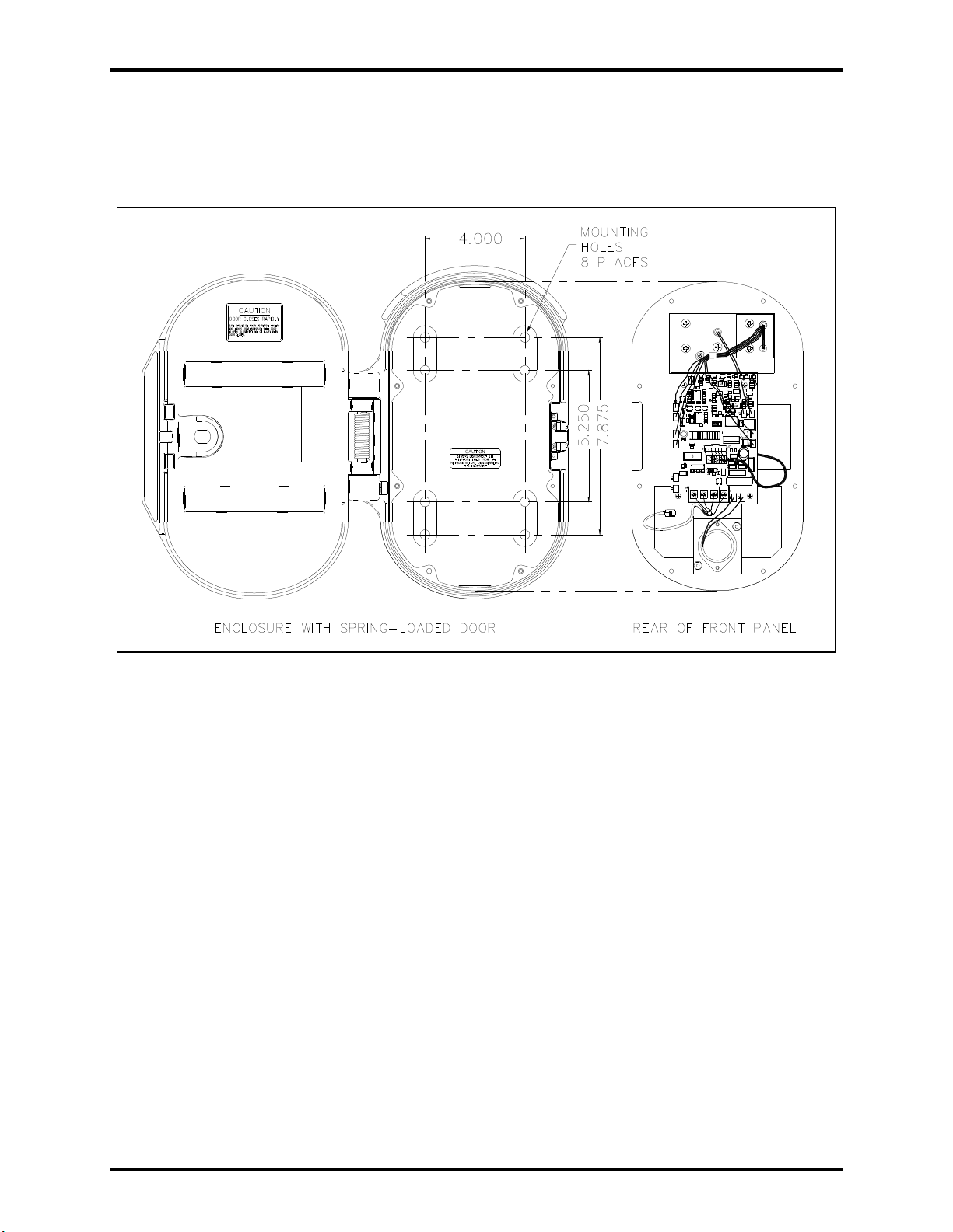
Model 226-001.........................................................................................................................................4
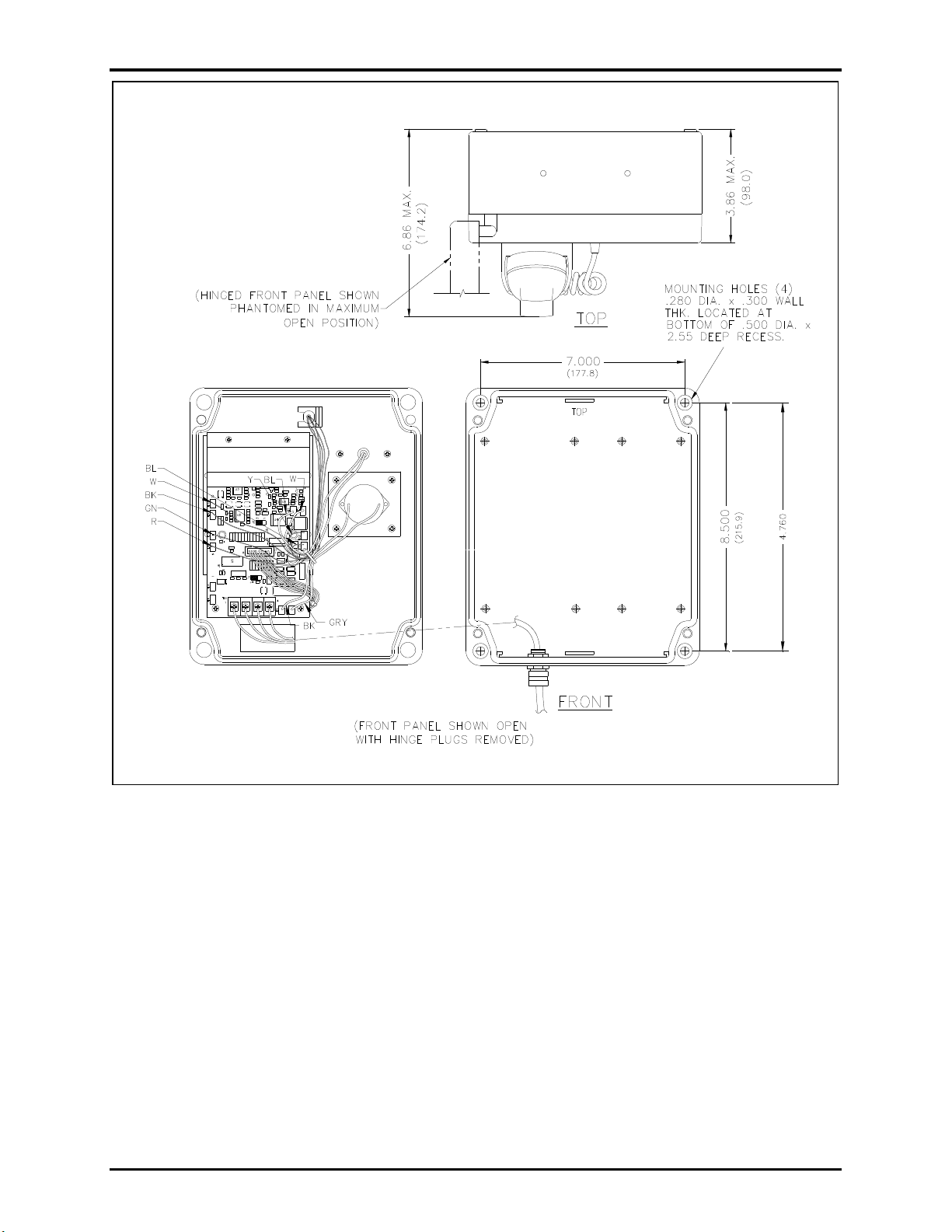
Model 246-001.........................................................................................................................................6
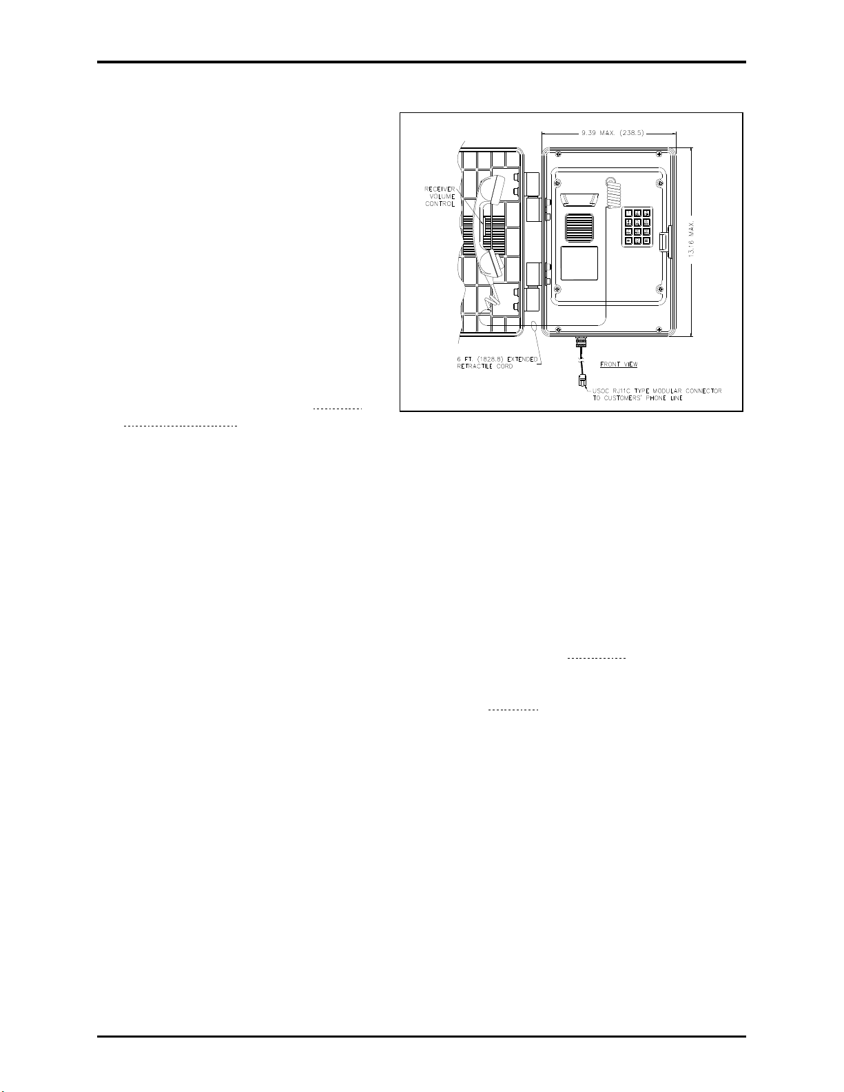
Model 256-001.........................................................................................................................................8
Model 276-001.......................................................................................................................................10
Flush-Mount Installation.....................................................................................................................10
Surface-Mount Installation using a 236 Series or Model 238-001 Enclosure ....................................11
Models 276-002BH and 276-002BHAC...............................................................................................12
Flush-Mount Installation.....................................................................................................................12
Surface-Mount Installation using the Model 238-003 Enclosure.......................................................13
Maintenance..................................................................................................................................14
Service....................................................................................................................................................14
Preventive Maintenance for Models 276-001/-002BH/-002BHAC...................................................14
Cleaning..............................................................................................................................................14
Prevention...........................................................................................................................................14
Volume Control Jumper Setting..........................................................................................................15
Auxiliary Output...................................................................................................................................15
Replacement Parts & Accessories ................................................................................................16
Specifications ................................................................................................................................17
Electrical (Typical)................................................................................................................................17
Environmental.......................................................................................................................................18
Mechanical.............................................................................................................................................18
Approvals.......................................................................................................................................19