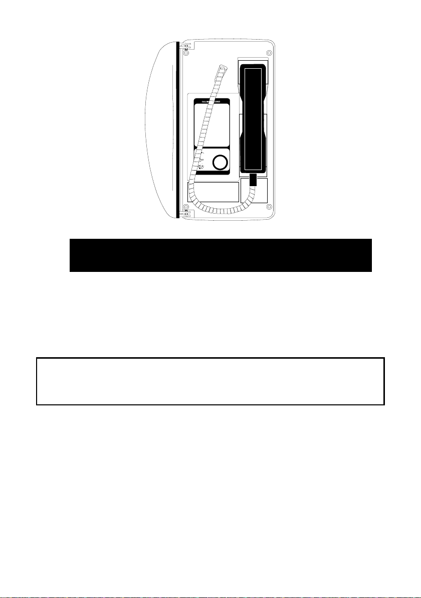
2 VoIP Titan Illuminated Crossing Telephone.
CONTENTS
1. Safety and Care Information.......................................................................3
2. Features.....................................................................................................3
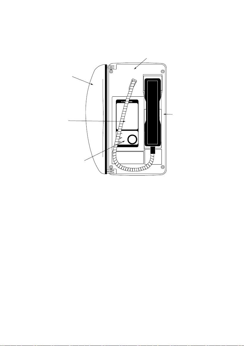
3. At a Glance.................................................................................................4
4. Quick Start Guide.......................................................................................6
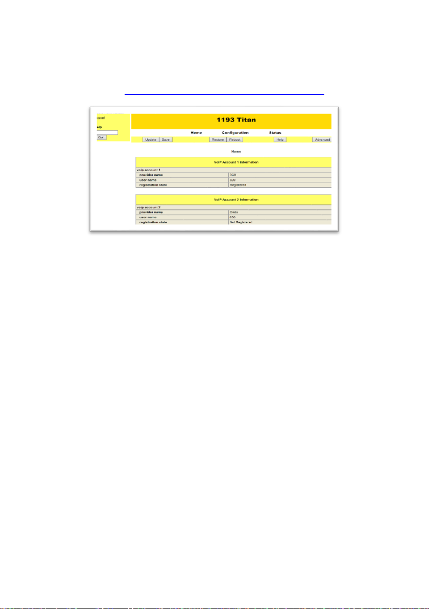
5. Operation / Testing.....................................................................................7
5.1. Illuminated Panel alert..................................................................7
5.2. Handset integrity alert ..................................................................7
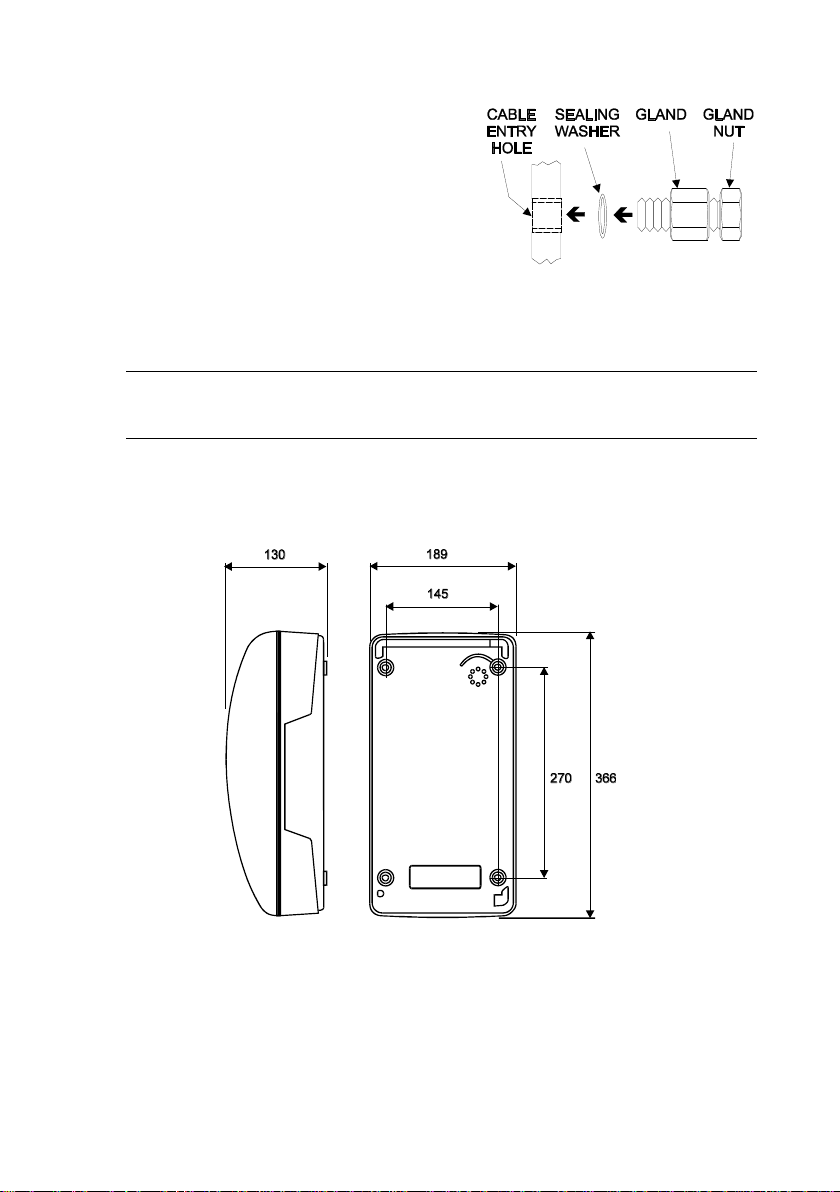
6. Mounting methods and dimensions............................................................7
6.1. General ........................................................................................7
6.2. Wall mounting ..............................................................................8
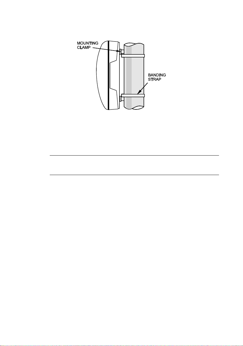
6.3. Pole mounting ............................................................................10
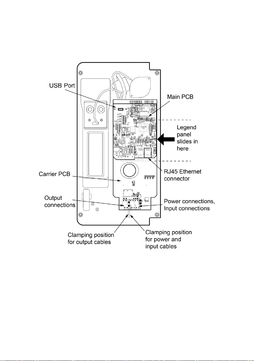
7. Connections and Installation ....................................................................11
7.1. General ......................................................................................11
7.2. IMPORTANT SAFETY INFORMATION.....................................12
7.3. Installation..................................................................................12
7.4. Connections...............................................................................13
8. Legend Panel. ..........................................................................................15
8.1. Legend panel dimensions ..........................................................15
8.2. Fitting the legend panel..............................................................16
9. Cleaning...................................................................................................17
9.1. Normal Cleaning ........................................................................17
9.2. Stainless Steel Push-buttons .....................................................17
9.3. Graffiti.........................................................................................17
10. Aftercare...................................................................................................17
11. Technical Specifications...........................................................................18
12. CE Declaration .........................................................................................21