MODEL 913H POWERIG® HYDRAULIC UNIT Alcoa Fastening Systems
8
MAINTENANCE (CONT.)
PREVENTIVE MAINTENANCE
An effective preventive maintenance program
includes scheduled inspections to detect and
correct minor troubles.
1. Verify that hydraulic hose fittings and
electrical connections are secure.
2. Inspect hoses for signs of damage.
REPLACE HOSES IF DAMAGE IS
DETECTED. Use of a defective hose may
result in Severe personal injury and
damage to the tool .
3. Inspect components during operation to
detect any abnormal heating, leakage,
vibration, or wear.
4. Inspect oil filter periodically. If necessary,
clean according to instruction tag.
5. Inspect hydraulic fluid periodically. Replace
if any evidence of impurities is detected.
6. Keep all exterior surfaces clean.
Perform the following maintenance on the
engine:
1. Check oil every five operating hours, and
each time before using Hydraulic Unit.
2. Change crankcase oil after first two hours of
operation. Thereafter, change crankcase oil
every 25 hours of operation. If power
source is operated in extremely dusty or
dirty environment, change oil every eight
hours of operation.
Unscrew oil drain plug (Figure 3 - Item 18),
tip engine toward oil drain hole and drain
completely. Replace oil drain plug and refill.
3. The air-cooled engine operates most
efficiently when cooling fins are kept clean.
Remove all dust and dirt from cylinder fins
and underside of housing, as required.
4. A dirty or clogged air cleaner results in
noticeable loss of engine power. Clean the
reusable-type air cleaner each 10 operating
hours, or more frequently if unit is operating
in dusty or dirty environment. To clean,
remove air cleaner (Figure 3 - Item 19) and
dip in gasoline.
5. Remove and inspect spark plug (Figure 2 -
Item 16) at each oil change. Keep
electrodes clean and free of carbon. Adjust
electrode gap to .030 inch. If electrodes are
pitted or burned or ceramic insulator is
cracked, replace spark plug. Before
installing a spark plug, coat threads lightly
with graphite grease.
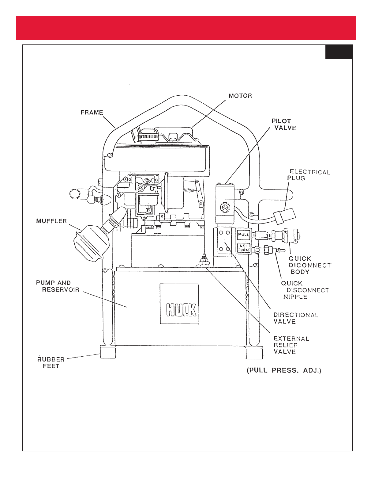
PRESSURE ADJUSTMENTS
NOTE: Do not adjust PULL or RETURN
pressure unless a T-10280 (earlier
model) or T-124833 Pressure Gauge is
on hand. Follow instructions supplied
with pressure gauge for proper pressure
checking and adjusting.
PULL pressure adjustment:
Refer to Figure 1.
1. Loosen jam nut on relief valve
2. Turn adjustment clockwise to increase
PULL pressure -- counter-clockwise
decreases pressure.
3. Tighten jam nut.
RETURN pressure adjustment:
Refer to Figure 3.
Same procedure as PULL adjustment.
NOTE: Relief valve jam nut must always
be tightened all the way clockwise once
pressure is set. Tightening will assure
settings won't "drift" while the hydraulic
unit is operating.