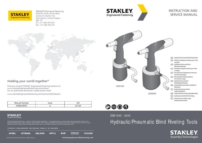
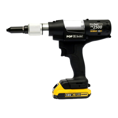
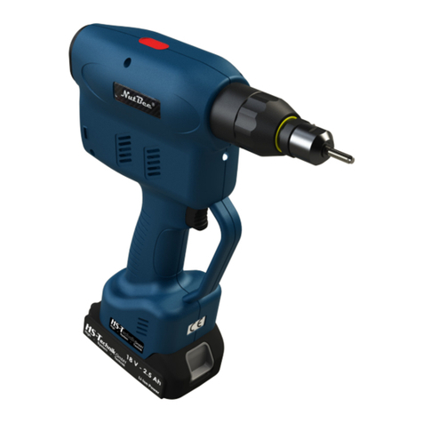
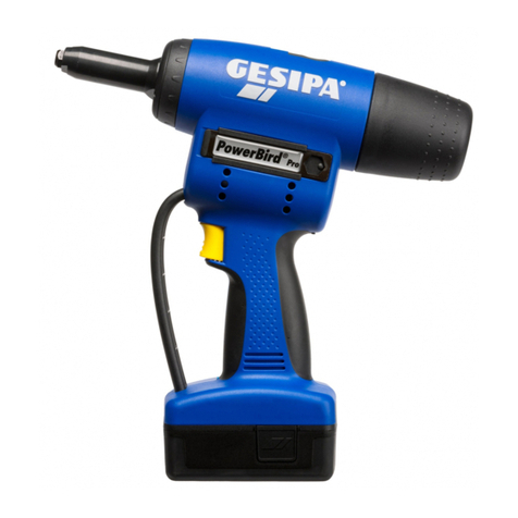
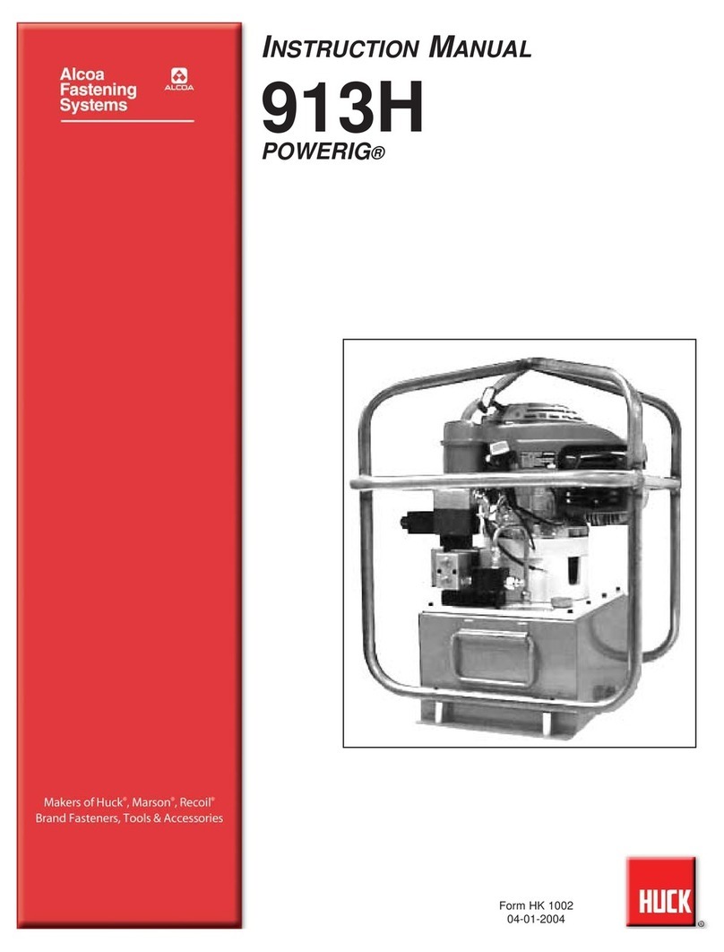
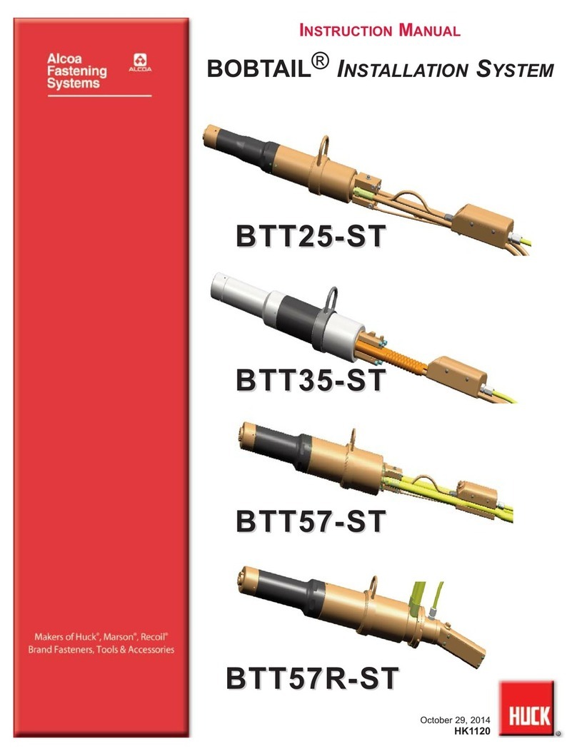
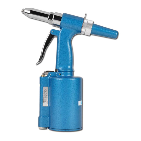
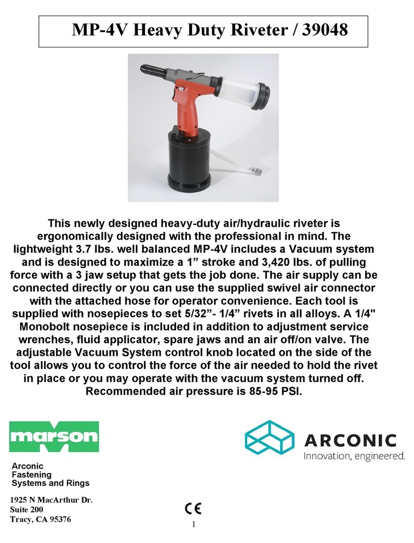
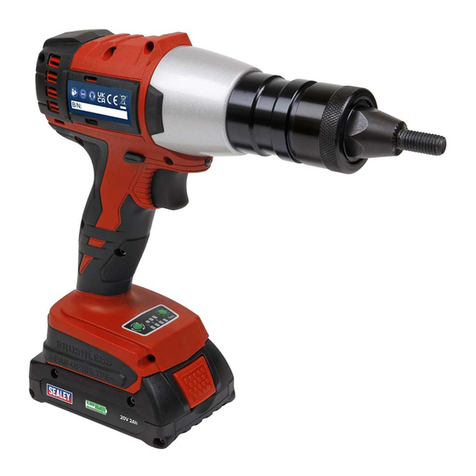
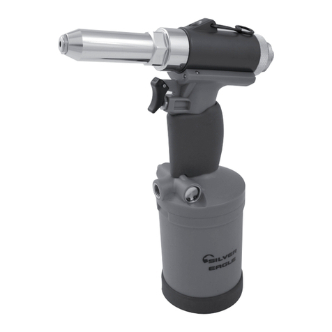
Huck ERT7 User manual

August 1, 2018
HK1061
Makers of Huck®, Marson®, Recoil®
Brand Fasteners, Tools & Accessories
Instruction Manual
ERT7 and ERT8
Ebbert Rivet Tools
Safety Instructions
3
4
Warning Stickers
4
Principle of Operation
5
Preparation for Use
5
Attaching Nose Assembly
to Tool
6
Kits and Accessories
6
Troubleshooting
6
Maintenance
7
Disassembly Instructions
8
Assembly Instructions
8
Components Drawings
9-10

2
ERT7 and ERT8 Ebbert Rivet Tools (HK1061)

3
ERT7 and ERT8 Ebbert Rivet Tools (HK1061)
I. GENERAL SAFETY RULES:
serious bodily injury.
required, and listed in the manual, are legibly marked on the tool. The
9. Tool is only to be used as stated in this manual. Any other use is
13. Never install a fastener in free air. Personal injury from fastener ejecting
may occur.
before installing the next fastener.
clear from front of tool.
18. Tools with ejector rods should never be cycled with out nose assembly
installed.
II. PROJECTILE HAZARDS:
inserted tools or accessories.
5. The risk of others should also be assessed at this time.
front of tool.
III. OPERATING HAZARDS:
3. Hold the tool correctly and be ready to counteract normal or sudden
movements with both hands available.
IV. REPETITIVE MOTION HAZARDS:
body.
discomfort and fatigue.
V. ACCESSORIES HAZARDS:
accessory.
consumables.
VI. WORKPLACE HAZARDS:
2. Proceed with caution while in unfamiliar surroundings; there could be
environments.
VII. NOISE HAZARDS:
VIII. VIBRATION HAZARDS:
warm and dry.
IX. PNEUMATIC / PNEUDRAULIC TOOL SAFETY INSTRUCTIONS:
3. Never direct air at yourself or anyone else.
5. Cold air should be directed away from hands.
8. Never carry an air tool by the hose.
Safety Instructions
Bold, Italic type, and underline:
instruction.
WARNINGS: Must be understood to avoid
severe personal injury.
CAUTIONS: Show conditions that will damage
equipment or structure.
4
ERT7 and ERT8 Ebbert Rivet Tools (HK1061)
Specifications
Warning Stickers
POWER SOURCE:
MAX OPERATING TEMP:
MAX FLOW RATE:
MAX AIR PRESSURE:
MAX PULL CAPACITY:
MIN RETURN CAPACITY:
MIN STROKE:
Both Models -
WEIGHT:
ERT7 -
ERT8 -
FASTENER SIZES: 1/8”, 5 mm, 6 mm
ERT7
ERT8
590517
590351
HIGH VELOCITY PINTAILS
DO NOT OPERATE WITH
MISSING OR DAMAGED
COLLECTION TUBE. ORIENT
TUBE END AWAY FROM
OPERATORS TO PREVENT
PERSONAL INJURY.
590561 590350
Where the following trade names are used in this manual, note:
DEXRON is a registered trademark of General Motors Corporation.
GLYD Ring is a registered trademark of Trelleborg Sealing Solutions
Germany GmbH
Loctite is a registered trademark of Henkel Corporation, U.S.A.
LUBRIPLATE is a registered trademark of Fiske Brothers Rening Co.
MERCON is a registered trademark of Ford Motor Corp.
MOLYKOTE is a registered trademark of Dow Corning Corporation
Never-Seez is a registered trademark of Bostik, Inc.
Quintolubric is a registered trademark of Quaker Chemical Corp.
Slic-tite is a registered trademark of LA-CO Industries, Inc.
Spirolox is a registered trademark of Smalley Steel Ring Company
Teon is a registered trademark of Chemours Company FC.
Threadmate is a registered trademark of Parker Intangibles LLC.
TRUARC is a trademark of TRUARC Co. LLC.
Vibra-Tite is a registered trademark of ND Industries, Inc. USA.

5
ERT7 and ERT8 Ebbert Rivet Tools (HK1061)
PULL CYCLE
Double Piston to the rear of the tool, and air is exhausted
out the bottom of the tool. The fastener is installed, and
NOTE: The ERT8 exhaust air exits through small holes
in the bottom of the Valve Body. (See Item 16 of ERT8
Assembly Drawing in this manual.)
RETURN CYCLE
and the tool is ready for the next fastener installation.
Principle of Operation
Preparation for Use
EPS6V or EPS6VL,
of this manual.
hoses to the unit.
3. Connect the cable attachment from hose assembly
to cylinder base of tool.
Turn ON the unit. Press and hold the tool trigger
for 30 seconds; then
to cycle the tool. Observe the action of the tool and
check for air leaks. Turn OFF the unit.
manual.
fasteners.

6
ERT7 and ERT8 Ebbert Rivet Tools (HK1061)
air hose
1.
a.
instruction manual.
b. Damaged trigger assembly.
c .
2.
a. Defective tool O-rings or loose connections at
tool.
3.
4.
5.
a. .
6. Pintail of fastener fails to break.
.
7.
a. Pulling Head assembly not correctly installed.
b. Tool or Pulling Head may need cleaning.
8. Excessive air leaking from trigger and tool will not
function.
a. Green and red air hoses may be switched.
Service Kit
ERT7 and ERT8 - 300471
P/N .P/N .
500779 O-ring 1 507665 Seal 2
500780 O-ring 1 300066 Seal 2
500794 O-ring 3 300071 Seal 1
Kits and Accessories
Troubleshooting
1. Remove Vacuum Tube Connector Assembly from
remaining Pulling Head Assembly.
outer sleeve. Install collet, jaws, follower assembly,
into end of tool. Tighten the sleeve nut.
3. Reinstall Vacuum Tube Connector Assembly to
nut.
Attaching Nose Assembly to Tool

7
ERT7 and ERT8 Ebbert Rivet Tools (HK1061)
Maintenance
GOOD SERVICE PRACTICES
lighted area; only standard hand tools are required in
number is given.
require force, use suitable soft materials to cushion
undue force. Reassemble tool with the same care.
section of this manual
Disassembly, Assembly, and/or Assembly Drawings.
Sealants, Lubricants, & Service Kits
you can get kit items from any regular retailer of these
items. See
information, see .
PREVENTIVE MAINTENANCE
System Inspection
the system to detect and correct minor troubles.
damage.
electrical connections are secure.
to detect abnormal heating, leaks, or vibration.
Power Unit Maintenance
Tool Maintenance
Whenever disassembled, and at regular intervals
Pulling Head Maintenance
from the grooves of the jaws.
.
Figure 1

8
ERT7 and ERT8 Ebbert Rivet Tools (HK1061)
Disassembly
Close attention must be directed to the recommended
instructions for each tool are given under that tool model
number heading. While the tools look similar, each tool
NOTE: The following procedure is for complete
disassembly of the tools. Disassemble only those
components necessary to replace damaged O-rings,
seals, Back-up rings, and worn and damaged
components. Disconnect the tool from the Power
Source prior to disassembly.
Removing the Hose Assembly
1. ERT7
2. ERT7 & ERT8
Rivet Tool Disassembly
1. Remove the Pulling Head Assembly from the tool;
remove all nicks and burrs from front of Piston Rod
Assembly.
2. ERT7
ERT8
remove the retaining ring from the rear of the Piston
Assembly. NOTE: Remove all nicks and burrs from
the rear of the piston to ensure removal of the end
cap and Double Piston without damaging them.
.
5. Remove the retaining ring from the rear of the Double
Piston. Pull the Piston Assembly out through the front
end of the tool.
6. Push out the Double Piston and Bulkhead through the
rear of tool. NOTE: It is not necessary to remove
the retaining ring from the cylinder.
Assembly
ERT8 tools
and 3. NOTE: Clean components with mineral spirits,
or similar solvent.
ease assembly. Assemble tool taking care not to damage
NOTE: Install retaining
rings with sharp edge of the retaining ring toward the
rear of the tool. When replacing seals, make sure they
are correctly positioned as shown in the Assembly
Drawing.
reassembly.
of gouges and nicks that will damage a new seal.
Small nicks and gouges can normally be removed
3. Install the bulkhead into the rear of the cylinder until
the cylinder.
the front or rear of the Piston Assembly, insert the
5. Install the Double Piston onto the rear of the Piston
Rod Assembly and into the cylinder until it bottoms
on the shoulder of the Piston Assembly.
6. Install the retaining ring at the back of the Double
the rear of the tool.
7. Install the rthe front end of the
Piston Rod Assembly.
8. ERT7
ERT8
secure with four screws. Torque the screws to 60–80
rear of tool and secure with the four screws. Torque
rear of the tool.
The Pulling Head Assembly and Hose Assembly can now
be installed.

9
ERT7 and ERT8 Ebbert Rivet Tools (HK1061)
Components Drawing & Parts List ERT7
1 300028 Piston Rod Guide 1
2 300004 Cylinder 1
4 507665 Seal 3
5 300145 Piston Assembly 1
6 500950 Retaining Ring 1
7 300065 Bulkhead 1
8 500794 O-ring 3
9 300066 Seal 2
10 500780 O-ring 1
11 300063 Double Piston 1
12 500995 Retaining Ring 2
13 300071 Seal 1
15 506268 Male Connector 1
16 300107 Guard 1
18 500779 O-ring 1
19 300042 Handle 1
20 300251 Trigger 1
21 500623 Pin 1
22 507660 Bleed Screw 2
23 300064 Screw Bearing Plate 2
24 500064 Socket Head Screw 8
26 500061 Socket Head Screw 4
27 500055 Socket Head Screw 4
28 501344 Dowel 1
29 300159 Valve 1

10
ERT7 and ERT8 Ebbert Rivet Tools (HK1061)
Assembly Drawing & Parts List ERT8
1 300058 Seal Housing 1
2 300005 Cylinder 1
4 507665 Seal 3
5 300144 Piston Assembly 1
6 500950 Retaining Ring 1
7 300065 Bulkhead 1
8 500794 O-ring 3
9 300066 Seal 2
10 500780 O-ring 1
11 300063 Double Piston 1
12 500995 Retaining Ring 2
13 300071 Seal 1
15 506268 Male Connector 1
16 300037 Valve Body 1
18 500779 O-ring 1
19 300105 Handle 1
20 300252 Trigger 1
21 500623 Pin 1
22 507660 Bleed Screw 2
23 300064 Screw Bearing Plate 2
24 500064 Socket Head Screw 8
26 500061 Socket Head Screw 4
28 501344 Dowel 1
29 300158 Valve 1

11
ERT7 and ERT8 Ebbert Rivet Tools (HK1061)
Limited Warranties
Limited Lifetime Warranty on BobTail® Tools:
that its BobTail® installation tools manufactured after
12/1/2016 shall be free from defects in materials and
useful lifetime. This warranty does
Two Year Limited Warranty on Installation Tools:
Huck International, Inc. warrants that its installation tools
and Powerig®
December 1, 2016 shall be free from defects in materials
90 Day Limited Warranty on Nose Assemblies and
Accessories:
Huck International, Inc. warrants that its nose assemblies
and accessories shall be free from defects in materials
literature.
Useful lifetime
International, Inc. for evaluation.
Tooling, Part(s) and Other Items not manufactured by
Huck:
any loss or damage, directly or indirectly, arising from the
warranty or for any claim for incidental or consequential
damages.
Huck shall not be liable for any loss or damage resulting
Huck Installation Equipment:
Huck International, Inc. reserves the right to make changes
without notice.
service technicians only.
below.
Eastern

CERTIFIED
MANAGEMENT
SYSTEM
ISO 9001-2015
ISO 14001-2015
Arconic Fastening Systems
Kingston Operations
www.afshuck.net/us
INDUSTRIAL NORTH AMERICA
1925 North MacArthur Drive
Tracy, CA 95376
PO Box 8117
INDUSTRIAL GLOBAL
55/1, Chowringhee Road,
1508 Centre Road
Clayton, Victoria
Australia 3168
58 Yinsheng Road,
215126 China
England TF3 3BQ
Chiyoda-ku, Tokyo
AEROSPACE NORTH AMERICA
3990A Heritage Oak Court
Simi Valley, CA 93063
www.afs-simivalley.com
AEROSPACE GLOBAL
Robert-Bosch Str. 4
Aichach 86551
Germany
15 Rue du Petit Albi
F-95611 Cergy Pontoise
France
27th Floor, 88 Hing Fat Street
Causeway Bay
Arconic Fastening Systems Tooling Support Locations
Huck fasteners and tooling. The
is only for general guidance with regard
and is not intended to create any warranty,
This manual suits for next models
1
Table of contents
Other Huck Rivet Tools manuals