Humanetics Q6 User manual

Q6 (Advanced 6 year old child)
User Manual

033-9900 User Manual Q6 (Advanced 6 year old) Rev. M
©2016 Humanetics Innovative Solutions Inc.
©
Page 2 of 96
For information on Humanetics products, please visit our web site at
www.humaneticsatd.com or contact:
Humanetics Innovative Solutions
47460 Galleon Drive
Plymouth, MI 48170, USA
Telephone: 734-451-7878
Fax: 734-451-9549
No part of this publication may be reproduced, stored in a retrieval system or transmitted in
any form or by any means, electronic, photocopying, recording, mechanical or otherwise,
without the express written consent of Humanetics Innovative Solutions.
Copyright © 2016 Humanetics Innovative Solutions, All rights reserved.
The information in this manual is furnished for informational use only, and is subject to
change without notice. Humanetics Innovative Solutions assumes no responsibility or liability
for any errors or inaccuracies that may appear in this manual.
Notice: This product may contain lead
A list of components that may contain lead is being maintained on the Humanetics website.
The list, organized by dummy type, shows subcomponents that may currently or in the past
have contained lead or a lead based alloy. Please refer to the Humanetics website under
ATD Lead Disclosure for information regarding lead in this product.
http://www.humaneticsatd.com/Lead_Disclosure

033-9900 User Manual Q6 (Advanced 6 year old) Rev. M
©2016 Humanetics Innovative Solutions Inc.
©
Page 3 of 96
Content
1. Introduction ....................................................................................................7
2. General Description and Features .....................................................................8
2.1
Design History................................................................................................. 8
2.2
Applications .................................................................................................... 8
2.3
Features .......................................................................................................... 9
2.4
Instrumentation Options................................................................................ 12
2.5
Main Dimensions........................................................................................... 12
2.6
Mass Distribution .......................................................................................... 13
2.7
Standard Dummy........................................................................................... 13
3. Instrumentation .............................................................................................14
3.1
General ......................................................................................................... 14
3.2
Transducers .................................................................................................. 14
3.3
Accelerometer Mounts................................................................................... 17
3.4
Angular Velocity Sensor Mounting ................................................................. 19
3.5
Abdomen Pressure Twin Sensor (ATPS) .......................................................... 21
3.6
Cable Routing and Protection ........................................................................ 23
4. Assembly - Disassembly ................................................................................24
4.1
General Overview .......................................................................................... 24
4.2
Head ............................................................................................................. 25
4.3
Neck.............................................................................................................. 28
4.4
Torso ............................................................................................................ 32
4.5
Lumbar Spine and Abdomen.......................................................................... 40
4.6
Pelvis............................................................................................................. 44
4.7
Legs .............................................................................................................. 46
4.8
Arms ............................................................................................................. 48
4.9
Abdomen ...................................................................................................... 51

033-9900 User Manual Q6 (Advanced 6 year old) Rev. M
©2016 Humanetics Innovative Solutions Inc.
©
Page 4 of 96
4.10
Neck Shield ................................................................................................... 52
4.11
Suit ............................................................................................................... 53
4.12
Hip Insert ...................................................................................................... 53
5. Pre-Test Checks ............................................................................................54
5.1
Inspection ..................................................................................................... 54
5.2
Click Stops and Arm Adjustment ................................................................... 55
5.3
Time Interval between Tests .......................................................................... 56
6. Dummy Parts List and Recommended Spare Parts............................................57
6.1
Dummy Parts................................................................................................. 57
6.2
Recommended Spare Parts ............................................................................ 60
7. Certification Equipment .....................................................................................61
7.1
Requirements ................................................................................................ 61
7.2
Equipment..................................................................................................... 62
7.3
Equipment Parts List...................................................................................... 67
8. Certification Tests .............................................................................................68
8.1
Head Certification.......................................................................................... 68
8.2
Certification of the Neck................................................................................ 72
8.3
Certification of the Lumbar Spine .................................................................. 78
8.4
Certification of the Abdomen......................................................................... 84
8.5
Certification of the Thorax ............................................................................ 85
9. Markers Location Coordinates and Relevant Dimensions .....................................92
10. Manual Update Log .......................................................................................94

033-9900 User Manual Q6 (Advanced 6 year old) Rev. M
©2016 Humanetics Innovative Solutions Inc.
©
Page 5 of 96
List of Figures
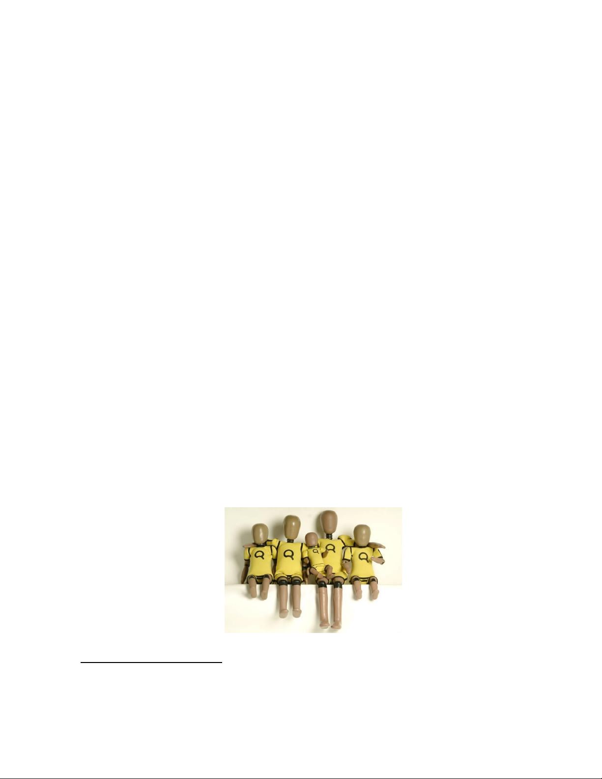
Figure 1. Q0 –Q6 dummies: from left to right Q1.5, Q3, Q0, Q6 and Q1.............................. 7
Figure 2. Accelerometer mounts for Q6 ......................................................................................... 18
Figure 3. Thorax uni-axial acceleration mounts I.AO (left) and I.AN (right)........................... 18
Figure 4. Pelvis uni-axial acceleration mounts I.AO (left) and I.AN (right) .............................. 18
Figure 5. Head uni-axial acceleration mounts I.AD (left) and I.AM (right)............................... 18
Figure 6. ATA ARS-01 (left) and ARS-06 (flanged version) (right)............................................. 19
Figure 7. DTS ARS’s on the special mount (DTS drawing TRIAX-M2D-1168) ...................... 20
Figure 8. Q6 Head instrumentation................................................................................................... 20
Figure 9. 40 mm APTS sensor ............................................................................................................ 21
Figure 10. CAD Picture of Q6 Abdomen showing ATPS sleeves assembled without sensors
and with foam plugs for certification.................................................................................................. 22
Figure 11. Q6 Head assembly (standard and optional instrumentation brackets shown)....... 26
Figure 12. Q6 Neck assembly ............................................................................................................... 29
Figure 13. Q6 Thorax assembly............................................................................................................ 33
Figure 14. IR-TRACC attachment hardware spine frontal (top left and right) and rib cage
side (bottom)........................................................................................................................................... 37
Figure 15. IR-TRACC should swing freely ......................................................................................... 38
Figure 16. Q6 side impact IR-TRACC arrangement........................................................................ 39
Figure 17. Lumbar spine assembly and abdomen.............................................................................. 43
Figure 18. Pelvis and hip joint assembly .............................................................................................. 45
Figure 19. Leg Assemblies ...................................................................................................................... 47
Figure 20. Arm Assemblies .................................................................................................................... 49
Figure 21. Neck Shield Installed: Left, Rear view; Right, Front view............................................ 52
Figure 22. Hip insert fitted on Q6: sitting position (left), straight legs (right) ........................... 53
Figure 23. Neck and lumbar spine head form test set-up for frontal test .................................. 62
Figure 24. Neck and lumbar spine head form test set-up for lateral test................................... 63
Figure 25. Q6 full-body impactor (accelerometer not shown) ..................................................... 65
Figure 26. Full body pendulum impactor suspension wire diagram.............................................. 66
Figure 27. Frontal Head drop certification set-up............................................................................ 70
Figure 28. Lateral Impact Head certification set-up –rear view of head.................................... 71
Figure 29. Q6 neck certification test set-up for frontal test.......................................................... 74
Figure 30. Q6 neck certification test set-up for lateral test........................................................... 76
Figure 31. Q6 lumbar spine certification test set-up for frontal test........................................... 80
Figure 32. Q6 lumbar spine certification test set-up for lateral test............................................ 82
Figure 33. Abdomen certification test set-up.................................................................................... 84
Figure 34. Neck Shield Installed and Removed ................................................................................. 86
Figure 35. Marker Positions on the Dummy...................................................................................... 92

033-9900 User Manual Q6 (Advanced 6 year old) Rev. M
©2016 Humanetics Innovative Solutions Inc.
©
Page 6 of 96
List of Tables
Table 1. Main dimensions ........................................................................................................................ 12
Table 2. Mass distribution ....................................................................................................................... 13
Table 3. Uni-axial accelerometers and mounts for thorax and pelvis .......................................... 17
Table 4. Tri-axial accelerometers and mounts for head .................................................................. 19
Table 5. Assembly and component part numbers for abdomens that can engage APTS
sensors ...................................................................................................................................................... 22
Table 6. Head assembly parts................................................................................................................. 25
Table 7. Neck assembly parts................................................................................................................. 28
Table 8. Torso assembly parts ............................................................................................................... 32
Table 9. IR-RTRACC attachment: part list frontal impact configuration ..................................... 36
Table 10. IR-RTRACC attachment: part list frontal impact configuration................................. 39
Table 11. Spine and abdomen assembly parts.................................................................................. 41
Table 12. Pelvis assembly parts............................................................................................................ 44
Table 13. Legs assembly parts.............................................................................................................. 46
Table 14. Arm assembly parts.............................................................................................................. 49
Table 15. Dummy parts list .................................................................................................................. 57
Table 16. Recommended spare parts................................................................................................. 60
Table 17. Q6 full body pendulum specifications .............................................................................. 65
Table 18. Q-Dummy certification equipment parts list ................................................................. 67
Table 19. Markers Head, Origin: Occipital Condoyle.................................................................... 93
Table 20. Markers Torso, Origin: Erected seating, Seat back (cable guide), bottom of pelvis
flesh- and Mid-sagittal-plane ................................................................................................................. 93
Table 21. Markers Arms, Origin: Elbow joint centre, Upper arm bone vertical, Lower arm
bone horizontal ....................................................................................................................................... 93
Table 22. Markers Legs, Origin: Knee joint centre, Upper leg bone horizontal, Lower leg
bone vertical ............................................................................................................................................ 93

033-9900 User Manual Q6 (Advanced 6 year old) Rev. M
©2016 Humanetics Innovative Solutions Inc.
©
Page 7 of 96
1. Introduction
In the late 1970s and early 1980s, TNO and others developed the P-dummies, a
series of child dummies that covers almost the complete child population up to
12 years. The P-series dummies are still test tools for the European regulation
ECE-R44 and are also adopted by many other standards.
In 1993, the International Child Dummy Working Group started the development
of a new series of child dummies as a successor to the P-series. This new series
was called the Q-series. Part of the development and evaluation of the Q-dummies
took place within European Research programs like CREST
1
, CHILD
2
, CASPER
3
and
EPOCh
4
all aiming at improving child safety in cars. As of December 2011, the
series is available in five age groups, representing a Newborn, 1 year, 1½ year, 3
year, 6 year and 10 year old child.
Nowadays members of this Q family are applied in UNECE Regulation R129, which
became effective per January 2013. Also, various consumer rating programs
world-wide apply Q dummies.
Humanetics reserves the right to make improvements or implement changes to
the dummy, the certification or the user manual if this is deemed necessary. We
will of course inform our customers of any changes or modifications should they
occur.
Figure 1. Q0 –Q6 dummies: from left to right Q1.5, Q3, Q0, Q6 and Q1
1
CREST. “Child Restraint System for Cars”, EC-contract number C-RTD SMT4-CT95-2019.
2
CHILD. “Child Injury Led Design”, EC-contract number G3RD-CT-2002-0079
3
CASPER. “Child Advanced Safety Project for European Roads”, EC Grant Agreement 218564.
4
EPOCh. “Enabling Protection for Older Children”, EC Grant Agreement 218744

033-9900 User Manual Q6 (Advanced 6 year old) Rev. M
©2016 Humanetics Innovative Solutions Inc.
©
Page 8 of 96
2. General Description and Features
2.1 Design History
The development of the Q-series, directed by the International Child Dummy
Working Group, resulted in a Q3 dummy in 1998, followed by the addition of the
Q6 dummy in 1999, and the Q1 in 2000.
Based on customer feedback and test results, Humanetics have received
comments on the dummies’ performance and durability. This has resulted in an
update program that was started in 2004. This update was aimed at a number of
issues with the Q dummies in the shoulder, and head/neck area. During this
period, the Q0 and Q1.5 were added to the family, based on Q-series
anthropometry and biofidelity data.
The European Enhanced Vehicle-safety Committee performed an extensive
evaluation program of the Q-series in 2004. A full report on a possible
recommendation for use of the dummies in ECE R44 tests is expected in 2005.
Results of the first evaluations have been published at the 19th Enhanced Safety
of Vehicles conference in 2005
5
. In 2006, the New Programme for the Assessment
of Child-restraint Systems (NPACS) adopted the Q dummies for their test
protocols.
2.2 Applications
The Q6 dummy is suitable for frontal as well as side impact CRS evaluations, to
be used for both homologation, consumer rating and research purposes.
Applications include:
Child Restraint Systems (CRS) type approval testing. This includes the UNECE
Regulation R129 in which the Q6 dummies will be applied from July 2017 on to
assess non-integral Child Restraint Systems (CRS). The Regulation R129 is
being introduced in phases including front and side assessment of CRS.
5
Assessing New Child Dummies and Criteria for Child Occupant Protection in Frontal Impact, Kate de Jager
et. Al, Enhanced Safety of Vehicles conference 2005. Paper no. 05-0157.

033-9900 User Manual Q6 (Advanced 6 year old) Rev. M
©2016 Humanetics Innovative Solutions Inc.
©
Page 9 of 96
Consumer rating tests. The dummy has been designed to withstand impact with
closing velocities up to an average Euro NCAP level. Since January, the Q6 is
being used in the Euro NCAP protocols together with the Q10 dummy. Other
NCAP organizations like A-NCAP will follow at a later point in time.
The European Test Consortium (ETC) for Child Restrain Seats uses the Q series
for their frontal and side impact consumer test procedures for CRS performance
rating
6
.
Out-of-position tests (OOP), including airbag interaction.
2.3 Features
The Q-dummies have improved biofidelity over the P-series. Biomechanical
information from children and scaled adult biomechanical response curves has
been used to define the dummy response. The anthropometry of the dummy is
based on CANDAT
7
data.
The dummies can be equipped with accelerometers, angular velocity sensors,
load cells and displacement sensors. This allows evaluation of the injury risk
under various circumstances.
Special attention has been paid to the handling characteristics of the dummy,
ensuring the dummy can be assembled and disassembled quickly, and
installing the dummy in the test configuration is simple and repeatable.
The influence of transducers upon the kinematics of the dummy is minimized,
and protection of transducers and cables is integrated in the dummy design.
6
New Program for the Assessment of Child Restraint Systems (NPACS), V. Sandner et., Enhanced Safety of
Vehicles conference 2009.
7
Anthropometric of Children for Dummy Design, D. Twisk et. Al., ECOSA Product Safety Conference.
Amsterdam. 1993.

033-9900 User Manual Q6 (Advanced 6 year old) Rev. M
©2016 Humanetics Innovative Solutions Inc.
©
Page 10 of 96
Head
The head is largely made from synthetics. The head cavity is large enough to allow
use of several instruments, including linear accelerometers and angular velocity
sensors.
Neck
The neck is flexible and allows shear and bending in all directions. The segmented
design allows a realistic rotational behavior. The neck is equipped with low stretch
neck-cord in order to prevent excessive elongation. The neck-cord is also
designed to act as a safety cord in case of rubber failure. A six channel load cell
can be mounted at the neck-head and neck-torso interface.
Thorax
The thorax of the child is represented by a single rib cage. The deformation can
be measured with an IR-TRACC (Infra-Red Telescoping Rod for Assessment of
Chest Compression) sensor. The shoulders are connected with a flexible joint to
the thorax, allowing deformation forward. Accelerometers can be mounted on
the spine to measure linear accelerations.
Abdomen
The abdomen is foam covered with skin. Biomechanical data from children has
been used to determine the required stiffness.
Lumbar Spine
The lumbar spine is a flexible rubber column, with a steel cable, which allows
shear and bending in all directions. A six channel load cell can be mounted
between the lumbar spine and the pelvis.

033-9900 User Manual Q6 (Advanced 6 year old) Rev. M
©2016 Humanetics Innovative Solutions Inc.
©
Page 11 of 96
Pelvis
The Q-dummy pelvis has removable hip joints. An accelerometer array can be
mounted in the pelvis. Special hip joints are available that allow the dummy to be
position in a standing posture.
Legs
The knee joints can be locked in any position. This feature can be used to facilitate
positioning the dummy in a standing position. Note that the dummy does not have
the ability to stand without support. It must be placed against some object, such
as the dashboard.

033-9900 User Manual Q6 (Advanced 6 year old) Rev. M
©2016 Humanetics Innovative Solutions Inc.
©
Page 12 of 96
2.4 Instrumentation Options
The complete list of instrumentation options includes 36 channels:
Head Ax, Ay, Az linear acceleration.
Head Wx, Wy, Wz angular velocity.
Upper Neck Fx, Fy, Fz forces and Mx, My, Mz moments.
Lower Neck Fx, Fy, Fz forces and Mx, My, Mz moments.
Thoracic Spine Ax, Ay, Az linear acceleration.
Thorax 'rib cage' Dx or Dy deflection.
Thorax 'rib cage' Ax and Ay linear acceleration (upper and lower
side)
Abdomen Pressure
Lower Lumbar Spine Fx, Fy, Fz forces and Mx, My, Mz moments.
Pelvic Ax, Ay, Az linear acceleration.
2.5 Main Dimensions
The main dimensions of the Q6-dummy are provided below.
Table 1. Main dimensions
Description *
Q6
Dimension
[mm]
Tolerance
± [mm]
Seating height (head tilted
forward)
601
9
Shoulder height (sitting)
362
7
Stature
1143
9
Chest depth * *
141
5
Shoulder width (maximum)
305
7
Hip width
223
7
Back of buttocks to front knee
366
5
Back of buttocks to popliteus,
sitting
299
5
*) Measurements are valid for the dummy without suit.
**) Chest depth is measured at the center line of the fixation hole for the displacement
transducer.

033-9900 User Manual Q6 (Advanced 6 year old) Rev. M
©2016 Humanetics Innovative Solutions Inc.
©
Page 13 of 96
2.6 Mass Distribution
The table below shows the masses of the various components of the dummy. The
masses given include accelerometer mounts, the IR-TRACC and all screws and
fasteners.
Table 2. Mass distribution
Component
Q6
Mass [kg]
Tolerance
± [kg]
Head + Neck (incl. acc. mount)
3.94
0.10
Torso (incl. acc. mounts & IR-
TRACC)
9.07
0.40
Legs (left & right)
6.90
0.10
Arms (left & right)
2.49
0.10
Suit
0.55
0.10
Total
22.95
0.80
2.7 Standard Dummy
The standard Q-dummy is delivered with the following items:
-One piece of clothing (a yellow suit);
-Structural replacements in the location of the load cells;
-One set of mounting blocks for use with uni-axial accelerometers.

033-9900 User Manual Q6 (Advanced 6 year old) Rev. M
©2016 Humanetics Innovative Solutions Inc.
©
Page 14 of 96
3. Instrumentation
3.1 General
The dummy accepts both accelerometers and load cells as standard
instrumentation. Angular velocity sensors (DTS-ARS and Applied Technologies
Associates type ARS-01 or ARS-06 (flanged version)) can be fitted to the head,
which requires an alternative head accelerometer mount. The dummy can be
equipped with uni-axial accelerometers for all locations. Tri-axial accelerometers
can be used on the pelvis and thorax location. The standard dummy will be
delivered including mounting blocks for uni-axial accelerometers.
The load cells or their structural replacements are a part of the dummy structure;
the structural replacements have to be used in absence of the actual transducer.
A 6-channel load cell (Humanetics model IF-217 or IF-218) can be placed in the
upper neck, lower neck and lumbar spine location.
Tilt sensor mounts are also available for head, thorax and pelvis to suit 2 axis
sensor type IES1402. Part Numbers are 033-1110 head, 033-4110 thorax, and
033-7110 pelvis.
3.2 Transducers
The Q6 dummy can be fitted to measure any or all of the following parameters
(see also notes below):
Head
Standard - 3 uni-axial accelerometers in head (Ax, Ay, Az)
Optional - 3 angular velocity sensors:
Applied Technologies Associates type ARS-01 or ARS-06 (flanged
version) or DTS-ARS.
Neck
Standard - Upper neck 6 channel load cell, 3 forces, 3 moments (Fx, Fy, Fz, Mx,
My, Mz). Humanetics Model IF-217 (350 Ohm) or IF-218 (120 Ohm).

033-9900 User Manual Q6 (Advanced 6 year old) Rev. M
©2016 Humanetics Innovative Solutions Inc.
©
Page 15 of 96
- Lower neck 6 channel load cell, 3 forces, 3 moments (Fx, Fy, Fz, Mx,
My, Mz). Humanetics Model IF-217 (350 Ohm) or IF-218 (120 Ohm).
Thorax
Standard - 3 uni-axial accelerometers (or tri-axial accelerometer) in upper spine
(Ax, Ay, Az).
- 1 IR-TRACC sensor to measure chest deformation, frontal or lateral
(Dx or Dy) (Humanetics model IF-362).
Optional - Additional accelerometers may be installed with double sided tape
on flat spots at the rib cage and the thoracic spine (Ax, Ay) (see
notes below).
Lumbar Spine
Standard - 6 channel load cell at lumbar spine/ pelvis interface (Fx, Fy, Fz, Mx,
My, Mz). Humanetics Model IF-217 (350 Ohm) or IF-218 (120 Ohm).
Abdomen
Optional - Twin pressure sensor
Pelvis
Standard - 3 uni-axial accelerometers (or tri-axial accelerometer) on pelvis
skeletal structure (Ax, Ay, Az).
Optional - Asis Load cell left and right (Fx, My) Prototype
Notes:
1. IR-TRACC sensor may be mounted in two ways, either to measure frontal or
lateral deformations. The IR-TRACC sensor cannot record the true deformation in
oblique impacts. It is recommended not be use the IR-TRACC in tests with
expected high oblique rib deformations; this can cause damage to the IR-TRACC
sensor, as it has limited range of motion in directions perpendicular to its sensitive
deflection direction.
2. Information on the installation of the instrumentation can be found in the
assembly/disassembly section of this manual.

033-9900 User Manual Q6 (Advanced 6 year old) Rev. M
©2016 Humanetics Innovative Solutions Inc.
©
Page 16 of 96
3. The Upper Neck Load Cell does not require any correction for measurement of
the moment around the OC joint. The (theoretical) OC joint coincides with the
neutral axis of the moment measurement of the (Humanetics) load cell.
4. Additional accelerometers may be mounted in the dummy for
additional/redundant information. There are no fixed points for attaching these
accelerometers. Instead, double-sided tape may be used to attach the
accelerometer to the desired location. Two accelerometers may be used to
measure deformation velocity and the deformation itself. The procedure is as
follows:
Install the accelerometers in the dummy. The sensitive axes of the transducers
should be aligned as good as possible. Furthermore, the accelerometers
should be installed in locations that are expected to retain their alignment
during the deformation phase. Make sure that the accelerometers are not
located on positions that may contact other parts of the dummy as a result of
deformation. To process and combine the data, first filter both signals at
CFC1000 according to SAE J211. Subtract the signals and integrate the result.
This results in the deformation velocity. Numerical integration of the
calculated velocity signal gives the deformation itself.
Note that this method gives an approximation of the actual deformation. The
accuracy is limited due to the fact that the accelerometers do not remain
properly aligned during the test and the numerical integrations that include
the small measurement errors of the accelerometers cumulative in the velocity
and displacement result. The longer the time interval is the larger the
cumulative error can be. Experience with the Q3 dummy shows that usage of
the acceleration integration method results in an under-estimation of the
deformation. At 4.3 m/s initial impact velocity the error is approximately 10%.
At 6.7 m/s it is approximately 20%.
5. ASIS load-cells for the Q6 dummy are currently under development. Prototypes
are available and evaluation testing is ongoing.

033-9900 User Manual Q6 (Advanced 6 year old) Rev. M
©2016 Humanetics Innovative Solutions Inc.
©
Page 17 of 96
3.3 Accelerometer Mounts
Humanetics support three brands/models of accelerometers or equivalents
Endevco 7264 and 7267A series
Entran EGAS Series and EGE3-73 Tri-axial.
Kyowa ASM Series
MSC 126M/CM Uni-axial accelerometers
Note: The tri-axial accelerometers Endevco 7267A and Entran EGE3-073
cannot be fitted to the head. The head will only accept uni-axial
accelerometers.
Note: Thorax and Pelvis locations will ONLY accept tri-axial transducers
with a side-entry cable.
The uni-axial accelerometers and mounts that can be used for the Q6 dummy
are listed Table 3. The mounts and their orientation are depicted in figure 2 to 5.
Tri-axial accelerometers and mounts are listed in Table 4.
Table 3. Uni-axial accelerometers and mounts for thorax and pelvis
Accelerometer Type
Location
Head Mount (only
uni-axial accels)
Thorax
Pelvis
ENTRAN
EGAS-FS-50
I.AD
I.AO
I.AO
KYOWA
ASM-200BA
I.AM
I.AN
I.AN
ENDEVCO
7264-2000
7264C-2000
I.AM
I.AN
I.AN
ENDEVCO
7264A-2000
7264B-2000
I.AD
I.AO
I.AO
MSC
126M/CM
I.AM
I.AN
I.AN

033-9900 User Manual Q6 (Advanced 6 year old) Rev. M
©2016 Humanetics Innovative Solutions Inc.
©
Page 18 of 96
Figure 2. Accelerometer mounts for Q6
Figure 3. Thorax uni-axial acceleration mounts I.AO (left) and I.AN (right)
Figure 4. Pelvis uni-axial acceleration mounts I.AO (left) and I.AN (right)
Figure 5. Head uni-axial acceleration mounts I.AD (left) and I.AM (right)
Up
Down
Front
Rear

033-9900 User Manual Q6 (Advanced 6 year old) Rev. M
©2016 Humanetics Innovative Solutions Inc.
©
Page 19 of 96
Table 4. Tri-axial accelerometers and mounts for head
Accelerometer Type
Location
Head Mount (only
uni-axial accels)
Thorax
Pelvis
ENDEVCO
7267A-1500 Tri-
axial
Not possible
Use Endevco
Mount base
Use Endevco
Mount base
3.4 Angular Velocity Sensor Mounting
The application of angular velocity sensors is possible in the head. There are two
options:
1. ATA ARS-01 or ARS-06 (flanged version) (see Figure 6) with special mount
block 020-1014.
The mount block 020-1014 consists of a base and three ATA ARS sensor
blanks of similar weight and size. Any of these ARS sensor blanks can be
replaced with an ATA ARS-01 or ARS-06 (flanged version) sensor. The 020-
2014 mounting block will accept the same mount block as the standard
accelerometer mounting for the head (I.AD or I.AM, see Figure 2). Note that
the arrangement of the accelerometers on the block should be different as
the block is mounted in to of 020-1013A and on the bottom of 020-1014,
as shown Figure 5. The ATA ARS sensor blanks should not be removed if
there are no sensors to replace them.
Figure 6. ATA ARS-01 (left) and ARS-06 (flanged version) (right)

033-9900 User Manual Q6 (Advanced 6 year old) Rev. M
©2016 Humanetics Innovative Solutions Inc.
©
Page 20 of 96
2. DTS ARS-12K with special combine accelerometer/ARS mount (DTS
drawing TRIAX-M2D-1168) on the standard bracket 020-1013A. The
sensor and the mount are shown in Figure 3.
Figure 7. DTS ARS’s on the special mount (DTS drawing TRIAX-M2D-1168)
Figure 8. Q6 Head instrumentation
Note: Both accelerometer bracket arrangements 020-1013A (standard) and
020-1014 (optional for ATA-ARS version) are shown in overlay.
Table of contents
Other Humanetics Test Equipment manuals