Humanetics Q Series User manual

036-9900 User Manual Q1 (Advanced 1 year old child) Rev H Page 1 of 86
© 2016 Humanetics Innovative Solutions
Q1 (Advanced 1 year old child)
User Manual

036-9900 User Manual Q1 (Advanced 1 year old child) Rev H Page 2 of 86
© 2016 Humanetics Innovative Solutions
For information on Humanetics products, please visit our web site at
www.humaneticsatd.com
or contact:
Humanetics Innovative Solutions
47460 Galleon Drive
Plymouth, MI 48170, USA
Telephone: 734-451-7878
Fax: 734-451-9549
No part of this publication may be reproduced, stored in a retrieval system or
transmitted in any form or by any means, electronic, photocopying, recording,
mechanical or otherwise, without the express written consent of Humanetics Innovative
Solutions.
Copyright © 2016 Humanetics Innovative Solutions, All rights reserved.
The information in this manual is furnished for informational use only, and is
subject to change without notice. Humanetics Innovative Solutions assumes no
responsibility or liability for any errors or inaccuracies that may appear in this
manual.
Notice: This product may contain lead
A list of components that may contain lead is being maintained on the Humanetics web site. The list,
organized by dummy type, shows subcomponents that may currently or in the past have contained
lead or a lead based alloy. Please refer to the Humanetics web site under ATD Lead Disclosure for
information regarding lead in this product. http://www.humaneticsatd.com/Lead_Disclosure

036-9900 User Manual Q1 (Advanced 1 year old child) Rev H Page 3 of 86
© 2016 Humanetics Innovative Solutions
Content
List of Figures............................................................................................................5
1. Introduction ....................................................................................................6
2. General Description and Features .....................................................................7
2.1
Design History................................................................................................. 7
2.2
Application...................................................................................................... 7
2.3
Features .......................................................................................................... 9
2.4
Instrumentation options Q1 dummy .............................................................. 10
2.5
Main Dimensions........................................................................................... 11
2.6
Mass Distribution .......................................................................................... 12
2.7
Standard Dummy........................................................................................... 12
3. Instrumentation .............................................................................................13
3.1
General ......................................................................................................... 13
3.2
Transducers .................................................................................................. 13
3.3
Accelerometer Mounts................................................................................... 16
3.4
Angular Velocity Sensor Mounting ................................................................. 21
3.5
Cable routing and protection......................................................................... 22
3.6
Abdomen Pressure Twin Sensor (APTS) .......................................................... 23
4. Assembly - Disassembly ................................................................................25
4.1
General Overview .......................................................................................... 25
4.2
Head ............................................................................................................. 25
4.3
Neck.............................................................................................................. 29
4.4
Torso ............................................................................................................ 32
4.5
Lumbar Spine ................................................................................................ 39
4.6
Pelvis............................................................................................................. 43
4.7
Legs .............................................................................................................. 46
4.8
Arms ............................................................................................................. 48
4.9
Abdomen ...................................................................................................... 52

036-9900 User Manual Q1 (Advanced 1 year old child) Rev H Page 4 of 86
© 2016 Humanetics Innovative Solutions
4.10
Suit............................................................................................................ 53
5. Pre-Test Checks ............................................................................................54
5.1
Inspection ..................................................................................................... 54
5.2
Click Stops and Arm adjustment.................................................................... 55
5.3
Time Interval between Tests .......................................................................... 56
6. Dummy Parts List...........................................................................................57
7. Certification Equipment..................................................................................60
7.1
Requirements ................................................................................................ 60
7.2
Equipment..................................................................................................... 61
7.3
Equipment Parts List...................................................................................... 66
8. Certification Tests ............................................................................................67
8.1
Head Certification.......................................................................................... 67
8.2
Certification of the Neck:............................................................................... 71
8.3
Certification of the Lumbar Spine .................................................................. 75
8.4
Certification of the Abdomen......................................................................... 80
8.5
Certification of the Thorax ............................................................................ 81
Manual Update Log ..................................................................................................85

036-9900 User Manual Q1 (Advanced 1 year old child) Rev H Page 5 of 86
© 2016 Humanetics Innovative Solutions
List of Figures
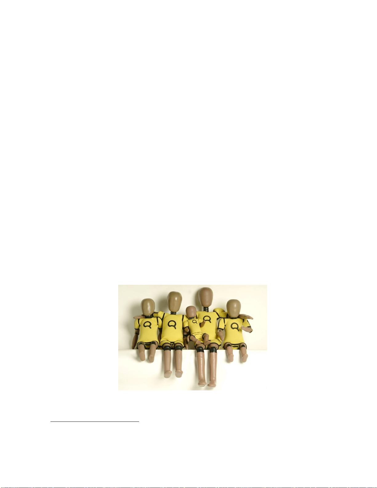
Figure 1. Q-Dummy Family........................................................................................... 6
Figure 2. Accelerometer mounts for Q1......................................................................... 17
Figure 3. Three ATA ARS-06S sensor and mounts .......................................................... 21
Figure 4. Three Accelerometers and three DTS ARS-12K on mount................................... 21
Figure 5. Head instrumentation –both accelerometer bracket arrangements ..................... 22
Figure 6. 30 mm Bladder details .................................................................................. 23
Figure 7. CAD Pictures of Q1/Q1.5 Abdomen showing APTS sleeves assembled without
sensors and with foam plugs for certification ..................................................................... 24
Figure 8. Head Assembly with standard 020-1013 accelerometer mount............................ 26
Figure 9. Head Assembly including instrumentation ........................................................ 28
Figure 10. Neck Assembly ......................................................................................... 29
Figure 11. Head and Neck ......................................................................................... 31
Figure 12. Thorax Assembly ...................................................................................... 33
Figure 13 Arm Assembly (Right) ................................................................................... 34
Figure 14 Arm Assembly (Left) ..................................................................................... 34
Figure 15. String pot attachment................................................................................ 37
Figure 16. String pot Side impact bracket .................................................................... 38
Figure 17. Lumbar Spine ........................................................................................... 40
Figure 18. Tighten nut down on the lumbar................................................................. 41
Figure 19. Abdomen Assembly ................................................................................... 42
Figure 20. Pelvis Assembly ........................................................................................ 43
Figure 21. Hip Joint (Right) ....................................................................................... 45
Figure 22. Hip Joint (Left) ......................................................................................... 45
Figure 23. Leg Assemblies, Right & Left ...................................................................... 48
Figure 24. Arm Assembly (Left).................................................................................. 49
Figure 25. Arm Assembly (Right)................................................................................ 51
Figure 26. Q1 Full Body Impactor............................................................................... 62
Figure 27. Wire Suspension ....................................................................................... 62
Figure 28. Head form ............................................................................................... 63
Figure 29. Head form Lumbar Spine set-up.................................................................. 65
Figure 30. Head drop Frontal ..................................................................................... 68
Figure 31. Head Drop Lateral..................................................................................... 70
Figure 32. Lumbar Spine Frontal ................................................................................ 76
Figure 33. Lumbar Spine Lateral................................................................................. 78
Figure 34. Abdomen Certification ............................................................................... 80

036-9900 User Manual Q1 (Advanced 1 year old child) Rev H Page 6 of 86
© 2016 Humanetics Innovative Solutions
1. Introduction
In the late 1970’s and early 1980’s, TNO and others developed the P-dummies, a series
of child dummies that covers almost the complete child population up to 12 years. The
P-series dummies are still test tools for the European regulation ECE-R44 and are also
adopted by many other standards.
In 1993 the international Child Dummy Working Group started with the development of
a new series of child dummies as a successor to the P-series. This new series was called
the Q-series.
As of September 2004 the series is available in four age groups, representing a 1 year,
1½ year, 3 year and 6 year old child. A new born dummy, Q0 is also available. In 2004 a
major update of the Q-dummy series has been performed resulting in the completion of
the series from Q0 till Q6. The Q1.5 dummy and the Q0 were added to the series, and
modifications were made to enhance durability and measurement capabilities.
Part of the development of the Q-dummies has taken place within the European Research
programs CREST
1
, and CHILD
2
both aimed at improving child safety in cars.
Humanetics reserves the right to make improvements or implement changes to the
dummy, the certification or the users’ manual if this is deemed necessary. We will of
course inform our customers of any changes or modifications as they occur.
Figure 1. Q-Dummy Family
1
CREST. “Child Restraint System for Cars”. EC-contract number C-RTD SMT4-CT95-2019. 1996-2000.
2
CHILD. “Child Injury Led Design”. EC contract number G3RD-CT2002-00791. 2002-2006.

036-9900 User Manual Q1 (Advanced 1 year old child) Rev H Page 7 of 86
© 2016 Humanetics Innovative Solutions
2. General Description and Features
2.1 Design History
In 1993 the international Child Dummy Working Group started with the development of
a new series of child dummies as a successor to the P-series. This new series was called
the Q-series. This development resulted in a Q3 dummy in 1998, later the Q6 (1999) and
the Q1 (2000) were added to the series.
Based on customer feedback and test results Humanetics have received comments on the
dummies performance and durability. This has resulted in an update program that was
started in 2004; this update aimed at a number of issues with the Q dummies in the
shoulder, and head/neck area. During this period the Q0 and Q1.5 were added to the
family, based on Q-series anthropometry and biofidelity data.
The European Enhanced Vehicle-safety Committee has performed an extensive evaluation
program of the Q-series in 2004; a full report on a possible recommendation for use of
the dummies in ECE-44 test was published in 2008. Results of the first evaluations have
been published ant the 19th Enhanced Safety of Vehicles conference in 2005
3
. In 2006 the
New Programme for the Assessment of Child-restraint Systems (NPACS) adopted the Q
dummies for their test protocols.
2.2 Application
The Q-dummy is a frontal impact child dummy, which is intended for both homologation
and research purposes. Possible applications include:
Child Restraint Systems (CRS) testing. This includes the European ECE R44 and the US
FMVSS 213 regulations. The Q-dummies have been designed to succeed the P-
dummies in CRS evaluation regulations.
3
ASSESSING NEW CHILD DUMMIES AND CRITERIA FOR CHILD OCCUPANT PROTECTION IN
FRONTAL IMPACT, Kate de Jager, Michiel van Ratingen, TNO Science and Industry, Philippe Lesire, Hervé
Guillemot, LAB (France), Claus Pastor, Britta Schnottale, BASt (Germany), Gonçal Tejera, Applus+IDIADA
(Spain)
Jean-Philippe Lepretre, UTAC (France). Paper no. 05-0157.

036-9900 User Manual Q1 (Advanced 1 year old child) Rev H Page 8 of 86
© 2016 Humanetics Innovative Solutions
EuroNCAP tests. The dummy has been designed to withstand impact with closing
velocities up to an average EuroNCAP level.
NPACS tests. The New Programme for the Assessment of Child-restraint Systems
(NPACS) protocols calls up the Q series for their frontal and side impact consumer test
procedures for CRS performance rating
4
.
Out-of-position tests (OOP), including airbag interaction.
ISO-side impact procedure.
4
Progress Report and Results From the NPACS Research Project, R Lowne. Third International Conference
on the Protection of Children in Cars, Munich, December 2005.

036-9900 User Manual Q1 (Advanced 1 year old child) Rev H Page 9 of 86
© 2016 Humanetics Innovative Solutions
2.3 Features
The Q dummies have improved biofidelity over the P-series. Biomechanical information
from children and scaled adult biomechanical response curves have been used to
define the dummy response. The anthropometry of the dummy has been based on
CANDAT data.
The dummies can be equipped with accelerometers, angular velocity sensors, load cells
and displacement sensors. This allows evaluation of the injury risk under various
circumstances.
Special attention has been paid to the handling characteristics of the dummy, ensuring
the dummy can be assembled and disassembled quickly, and installing the dummy in
the test configuration is simple and repeatable.
The influence of transducers upon the kinematics of the dummy is minimized, and
protection of transducers and cables is integrated in the dummy design.
Head
The head is largely made from synthetics. The head cavity is large enough to allow use
of several instruments, including linear accelerometers and angular velocity sensors.
Neck
The neck is flexible and allows shear and bending in all directions. The segmented design
allows a realistic rotational behavior. The neck is equipped with low-stretch and high
yield strength, low stretch synthetic fiber cord in order to prevent excessive elongation.
The neck-cord is also designed to act a safety in case of rubber failure. A six channel
load cell can be mounted at the neck-head interface.
Thorax
The thorax of the child is represented with a single rib-cage. The deformation can be
measured with a string potentiometer. The shoulders are connected with a flexible joint
to the thorax, allowing deformation forwards. Accelerometers can be mounted on the
spine to measure linear accelerations.
Abdomen
The abdomen is foam covered with skin. Biomechanical data from children has been used
to determine the required stiffness.

036-9900 User Manual Q1 (Advanced 1 year old child) Rev H Page 10 of 86
© 2016 Humanetics Innovative Solutions
Lumbar spine
The lumbar spine is a flexible rubber column, which allows shear and bending in all
directions. A six channel load cell can be mounted between the lumbar spine and the
pelvis.
Pelvis
The Q-dummy pelvis has removable hip joints. An accelerometer array can be mounted
in the pelvis. Special hip joints are available that allow to position the dummy in a standing
position.
Legs
The knee joints can be locked in any position. This feature can be used to facilitate
positioning the dummy in a standing position. Note that the dummy does not have the
ability to stand without support. It must be placed against some object, such as the
dashboard.
2.4 Instrumentation options Q1 dummy
The complete list of instrumentation options include:
Head Ax, Ay, Az linear acceleration.
Head Wx, Wy, Wz angular velocity.
Upper Neck Fx, Fy, Fz forces and Mx, My, Mz moments.
Thoracic Spine Ax, Ay, Az linear acceleration.
Thorax 'ribcage' Dx or Dy deflection.
Lower Lumbar Spine Fx, Fy, Fz forces and Mx, My, Mz moments.
Pelvic Ax, Ay, Az linear acceleration.

036-9900 User Manual Q1 (Advanced 1 year old child) Rev H Page 11 of 86
© 2016 Humanetics Innovative Solutions
2.5 Main Dimensions
The main dimensions of the Q-dummy series are described below.
Nr
Description **
Q1
Dimension [mm]
Tolerance
± mm
1
Sitting height (head tilted forward)
479
9
2
Shoulder height
298
7
3
Stature
740
9
4
Chest depth *
114
5
5
Shoulder width
227
7
6
Hip width
191
7
7
Buttock to front knee
211
5
8
Buttock to popliteus, sitting
161
5
*) the Chest depth is measured at the center line of the string attachment of the
displacement transducer.
**) The measurements are valid for the dummy without suit.

036-9900 User Manual Q1 (Advanced 1 year old child) Rev H Page 12 of 86
© 2016 Humanetics Innovative Solutions
2.6 Mass Distribution
The table below shows the masses of the various components of the dummy. The masses
given include accelerometer mounts, the string potentiometer or IR-TRACC and all screws
and fixings.
Component
Q1
Mass [kg]
Tolerance
[kg]
Head + neck (incl. acc. mount)
2.41
0.10
Torso (incl. acc. Mounts, string pot-meter)
4.21
0.25
Upper legs
1.00
0.10
Lower legs
0.82
0.10
Upper arms
0.45
0.10
Lower arms
0.44
0.10
Suit
0.27
0.05
Total
9.60
0.30
2.7 Standard Dummy
The standard Q-dummy is delivered with the following items:
-One piece of clothing (a yellow suit);
-Structural replacements in the location of the load cells;

036-9900 User Manual Q1 (Advanced 1 year old child) Rev H Page 13 of 86
© 2016 Humanetics Innovative Solutions
3. Instrumentation
3.1 General
The dummy accepts both accelerometers and load cells as standard instrumentation.
Angular velocity sensors can be fitted to the head; this requires an alternative head
accelerometer mount. The dummy can be equipped with uni-axial accelerometers for all
locations. Tri-axial accelerometers can be used on the pelvis and thorax location. The
load cells or its structural replacements are a part of the dummy structure; the structural
replacements have to be used in absence of the actual transducer. A 6-channel load cell
(model IF-217 or IF-218) can be placed in the upper neck and lumbar spine location.
3.2 Transducers
The Q1 dummy can be fitted to measure of the following parameters:
Head
Standard - 3 uni-axial accelerometers in head (Ax, Ay, Az)
Optional - 3 angular velocity: Applied Technologies Associates, ARS-06S
-3 angular velocity DTS ARS-12K
Neck
Standard - Upper neck 6 channel load cell, 3 forces, 3 moments (Fx, Fy, Fz, Mx, My,
Mz).
Model IF-217 (350 Ohm) or IF-218 (120 Ohm).
Thorax
Standard - 3 uni-axial accelerometers (or tria-xial accelerometer) in upper spine (Ax,
Ay, Az).
- 1 string potentiometer to measure chest deformation, frontal or lateral
(Dx or Dy)
Optional - additional accelerometers may be installed on the thorax and the rib
cage (see notes below) (Ax, Ay).

036-9900 User Manual Q1 (Advanced 1 year old child) Rev H Page 14 of 86
© 2016 Humanetics Innovative Solutions
Lumbar Spine
Standard - 6 channel load cell at lumbar spine/ pelvis interface (Fx, Fy, Fz, Mx, My,
Mz).
Model IF-217 (350 Ohm) or IF-218 (120 Ohm).
Abdomen
Optional -Abdomen Twin Pressure Sensor (ATPS)
Pelvis
Standard -3 uni-axial accelerometers (or tria-xial accelerometer) on pelvis skeletal
structure (Ax, Ay, Az).

036-9900 User Manual Q1 (Advanced 1 year old child) Rev H Page 15 of 86
© 2016 Humanetics Innovative Solutions
Notes:
1. The string potentiometer may be mounted in two ways, either to measure frontal or
lateral deformations. The string potentiometer must not be used in deformations with
expected rib- deformation speeds exceeding 5 m/s.
2. Information on the installation of the instrumentation can be found in the
assembly/disassembly section of this manual.
3. The Upper Neck Load Cell does not require any correction for measurement of the
moment around the OC joint. The (theoretical) OC joint coincides with the neutral axis of
the moment measurement of the load cell.
4. Additional accelerometers may be mounted in the dummy for extra/redundant
information. There are no fixed points for attaching these accelerometers. Instead,
double-sided tape may be used to attach the accelerometer to the desired location. Two
accelerometers may be used to measure deformation velocity and the deformation itself.
The procedure is as follows:
Install the accelerometers in the dummy. The sensitive axes of the transducers should
be aligned as good as possible. Furthermore, the accelerometers should be installed
in locations that are expected to retain their alignment during the deformation phase.
Make sure that the accelerometers are not located on positions that may contact other
parts of the dummy as a result of deformation. To process and combine the data first
filter both signals at CFC1000 according to SAE J211. Subtract the signals and
integrate the result. This results in the deformation velocity. Numerical integration of
this signal gives the deformation itself.
Note that this method gives an approximation of the actual deformation. The
accuracy is decreased due to the fact that the accelerometers cannot be properly
aligned during the test. Experience with the Q3 dummy shows that usage of the
acceleration integration method results in an under-estimation of the deformation.
At 4.3 m/s initial impact velocity the error is approximately 10%. At 6.7 m/s it is
approximately 20%.

036-9900 User Manual Q1 (Advanced 1 year old child) Rev H Page 16 of 86
© 2016 Humanetics Innovative Solutions
3.3 Accelerometer Mounts
Humanetics support three brands/models of accelerometers or equivalent
Endevco 7264 and 7267A series
Entran EGAS Series and EGE3-73 Tri-axial.
Kyowa ASM Series
MSC 126M/CM Uni-axial accelerometers
Note: The tria-xial accelerometers Endevco 7267A and Entran EGE3-073 cannot
be fitted to the head. The head will only accept uni-axial accelerometers.
Note: Thorax and Pelvis locations will ONLY accept tri-axial transducers with a
side-entry cable.
The following accelerometers ARS sensors and mounts can be used for the Q1 Dummy.
Only Uni-axial accelerometers:
Accelerometer
Type
Location
Head mount
(only Uni-
axial accels)
Head Mount
for uni-accels
& DTS ARS
sensor
(Optional)
Head Mount
for ATA ARS-
06S sensor
(optional)
Head Mount for
Uni-accels &
ATA ARS-06S
sensor (optional)
Thorax
Pelvis
ENTRAN
EGAS-FS-50
I.AD
036-1101
036-1251
I.AD & 036-1251
I.AO
I.AO
KYOWA
ASM-200BA
I.AM
034-1201
036-1251
I.AM & 036-1251
I.AN
I.AN
ENDEVCO
7264-2000
I.AM
034-1201
036-1251
I.AM & 036-1251
I.AN
I.AN
ENDEVCO
7264A/B-2000
I.AD
036-1101
036-1251
I.AD & 036-1251
I.AO
I.AO
MSC 126M/CM
I.AM
034-1201
036-1251
I.AM & 036-1251
I.AN
I.AN

036-9900 User Manual Q1 (Advanced 1 year old child) Rev H Page 17 of 86
© 2016 Humanetics Innovative Solutions
Tri-axial:
Accelerometer
Type
Location
Head Mount
(only Uni-
axial accels)
Head Mount
for Uni-accels
&DTS ARS
sensor
(Optional)
Head Mount
for ATA ARS-
06S sensor
(optional)
Head Mount for
Uni-accels &
ATA ARS-06S
sensor (optional)
Thorax
Pelvis
ENDEVCO
7264A-1500
Not Possible
Not Possible
Not Possible
Not Possible
Use
Endevco
Mount
Base
Use
Endevco
Mount
Base
Figure 2. Accelerometer mounts for Q1
Humanetics also support two models of angular:
Applied Technologies Associates ARS-06S
DTS ARS-12K

036-9900 User Manual Q1 (Advanced 1 year old child) Rev H Page 18 of 86
© 2016 Humanetics Innovative Solutions
Thorax accel mount, I.AO
Up
Down
Up
Down

036-9900 User Manual Q1 (Advanced 1 year old child) Rev H Page 19 of 86
© 2016 Humanetics Innovative Solutions
Thorax accel mount, I.AN
Pelvis accel mount, I.AO
Pelvis accel mount, I.AN
Front
Rear
Front
Rear

036-9900 User Manual Q1 (Advanced 1 year old child) Rev H Page 20 of 86
© 2016 Humanetics Innovative Solutions
Head accel mount, I.AD
Head accel mount, I.AM
This manual suits for next models
2
Table of contents
Other Humanetics Test Equipment manuals