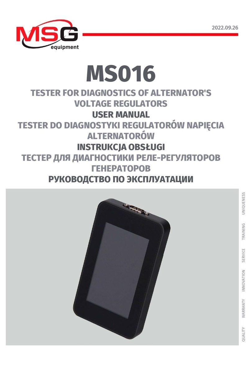
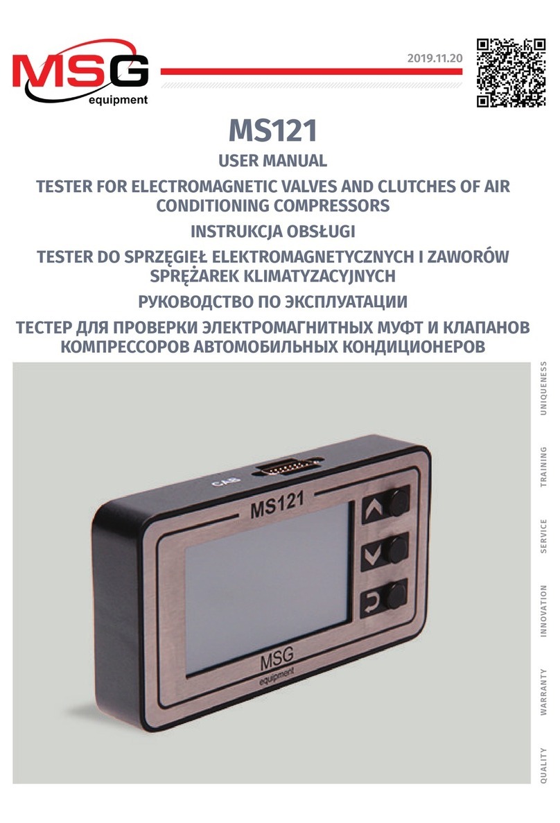
MSG Equipment MS015 User manual

2022.09.26
MS015
TESTER FOR DIAGNOSTICS
OF ALTERNATOR'S VOLTAGE REGULATORS
USER MANUAL
TESTER DO DIAGNOSTYKI
REGULATORÓW NAPIĘCIA ALTERNATORÓW
INSTRUKCJA OBSŁUGI
ТЕСТЕР ДЛЯ ДИАГНОСТИКИ
РЕЛЕ-РЕГУЛЯТОРОВ ГЕНЕРАТОРОВ
РУКОВОДСТВО ПО ЭКСПЛУАТАЦИИ
UNIQUENESS
TRAINING
SERVICE
I
NNOVATION
WARRANTY
QUALITY


English
User manual
3
CONTENTS
INTRODUCTION....................................................................................................................................................4
1. APPLICATION....................................................................................................................................................4
2. SPECIFICATIONS..............................................................................................................................................5
3. EQUIPMENT SET ..............................................................................................................................................6
4. TESTER DESCRIPTION....................................................................................................................................6
4.1. Tester menu ......................................................................................................................................... 8
4.2. Alternator diagnostics modes ..........................................................................................................9
5. APPROPRIATE USE........................................................................................................................................ 11
5.1. Safety regulations..............................................................................................................................12
5.2. Alternator diagnostics procedure..................................................................................................12
6. TESTER MAINTENANCE ................................................................................................................................13
6.1. Software update.................................................................................................................................13
6.2. Cleaning and care..............................................................................................................................13
7. TROUBLESHOOTING GUIDE.........................................................................................................................14
8. RECYCLING.....................................................................................................................................................14
APPENDIX 1.........................................................................................................................................................15
CONTACTS...........................................................................................................................................................18
APPENDIX 2 ....................................................................................................................................................... 53

English
Tester MS015
4
INTRODUCTION
Thank you for choosing the product of MSG equipment.
The actual manual contains information on the test bench purpose, package contents, technical
characteristics, and safe operation rules.
Read carefully this manual before putting MS015 (hereinafter “the tester”) into operation, take
special training at the equipment manufacturing facility if necessary.
As the tester is being continuously improved, some changes made to the equipment design,
package set, or firmware may not be reflected in this user manual. The tester firmware is
updateable, so its maintenance can be terminated without prior notice to users.
1. APPLICATION
The tester is designed for the express diagnostics of the automotive 12V alternators with the
controlled or digital voltage regulators - without the dismounting of the units from a car. Besides,
the diagnostics can be carried out at the bench that provides the drive and the load to alternator.
The diagnostics of automotive alternators takes into account the following criteria:
– Stabilizing voltage;
–The frequency and the duty cycle through the terminal FR - the voltage regulator feedback that
demonstrates the rate of the activated rotor winding coil condition.
For COM alternators:
– ID;
– Protocol;
– data exchange speed;
– regulator self-diagnostics errors.

English
User manual
5
2. SPECIFICATIONS
Main
Power supply
10-18 V from vehicle battery or from a
bench
Dimensions (L x W x H), mm
120×65×18
Weight, kg
0.3
Display
TFT-LCD display with touchscreen
Diagonal – 2.8"
Protection rating
IP20
Diagnostics of voltage regulators
Rated voltage of the diagnosed units, V
12
Types of diagnosed voltage regulators
COM (LIN, BSS), SIG, RLO, RVC, C KOR, P-D,
C JAP
Tested parameters
- Stabilizing voltage;
- FR (voltage regulator response to
alternator load).
For COM voltage regulators:
- ID;
- Protocol type;
- Data exchange rate;
- Voltage regulator self-diagnostic errors.
Voltage measurement accuracy, V ±0.2
Additional functions
Software update Available
Voltage regulators load Not available

English
Tester MS015
6
3. EQUIPMENT SET
The equipment set includes:
Item name
Number of
pcs
Tester MSG MS015
1
MS0128 – diagnostic cable
1
Cable for the connection of the extra +
1
User Manual (card with QR code)
1
4. TESTER DESCRIPTION
The tester is portable, with the touchscreen to control the functions (see fig.1).
Figure 1. Tester overall view

English
User manual
7
On the top of the tester there’s a port for the connection of the diagnostic cable (fig. 2).
Figure 2. Diagnostic cable connection port
At the bottom of the tester there’s MisroSD port that is used for the software update (fig. 3).
Figure 3. MicroSD port
The supply slip includes two cables (fig. 4-5): the diagnostic cable and the auxiliary cable - for
the connection of the additional positive wire.
Figure 4. Diagnostic cable
The diagnostic cable has the following colour codes:
•Red – В+– battery positive terminal, alternator connector. It supplies the power to the tester
and indicates В+voltage;

English
Tester MS015
8
•Black – В-– battery negative terminal (alternator body);
•Yellow – GC – for the connection with the terminal that controls the alternator voltage
regulator. This adapting wire is connected to the following terminals: D, SIG, RC, L(RVC), C, G,
RLO, LIN, COM.
•Green – FR – for the connection with the alternator connector terminal that transmits the data
about the current alternator load. This adapting wire is connected to the following terminals:
FR, DFM, M, LI.
Figure 5. Cable for the connection of the extra +
4.1. Tester menu
The main menu of the tester consists of (fig. 6):
Figure 6. Tester main menu
1– Diagnosed alternator type options. Press once the required icon to select the alternator type.
The selected type icon turns highlighted.

English
User manual
9
2– Alternator connector types.
3– Button TEST – to get the mode of the diagnostics of the chosen alternator type.
4.2. Alternator diagnostics modes
If you choose the diagnostics of COM alternator the following information is displayed (fig. 7):
Figure 7. COM alternator diagnostics screen
1– Diagnosed alternator type.
2– buttons -V and +V modify the value of the set stabilizing voltage of alternator. Press once to
change the value with 0.2V pitch.
3– set stabilizing voltage.
4– alternator output voltage - measured.
COM PR. – voltage regulator protocol. The following protocols are displayed: LIN1.3 (on screen -
LIN1), LIN2.0 (on screen - LIN2).
ID – voltage regulator identification number. It’s a unique number of the receiver of the commands
from the engine control unit. When installing a new alternator into a car, it’s important that ID
corresponded to the original one, otherwise, a car won’t “accept” the unit, and the control unit
will indicate the alternator error.
COM SPEED – data transmission speed, between the voltage regulator and the car electronic
control unit. At LIN protocol, the following the speed rates can be displayed:
• L – 2400 Bd (low);
• M – 9600 Bd (medium);
• H– 19200 Bd (high).

English
Tester MS015
10
TYPE – voltage regulator connection type. The name of the protocol BSS is displayed, as well as
12 types of LIN protocol: A1, A2, A3, A4, B1, B2, B3, B4, C3, D1, D2, E1.
EXCITATION – current value in the winding coil of alternator excitation. This parameter is read
from the voltage regulator by LIN protocol (the parameter is displayed in %).
ERRORS – indicator of errors that the regulator transmits to engine control unit. The following
errors may happen:
• EL – electric;
• МЕС – mechanic;
• ТН – overheating.
Once the error is detected, it’s highlighted by red.
SUPPLIER – the voltage regulator manufacturer.
SUPP. ID – the voltage regulator ID generated by the manufacturer.
BACK – exit from the diagnostics mode.
When you choose the mode of the diagnostics of the following alternator types: SIG, RLO, RVC,
C KOREA, P/D, C JAP. alternator types, the following information can be displayed (fig. 8):
Figure 8. Alternator diagnostics window:
SIG, RLO, RVC, C KOR., P/D, C JAP.
1– Diagnosed alternator type.
2– buttons -V and +V modify the value of the set stabilizing voltage of alternator. Press once to
change the value with 0.2V pitch.

English
User manual
11
3– set stabilizing voltage. For C JAP. alternator types, the OFF value is displayed – the voltage
regulator operation mode that corresponds to the output voltage from 12.1 up to 12.7 V. Press once
-V or +V to start the voltage regulator mode ON – the voltage regulator operation mode that
corresponds to the output voltage from 14 up to 14.4 V.
4– alternator output voltage - measured.
FR – frequency of PWM-signal that is transmitted by FR terminal.
DFM – duty ratio of PWM-signal, received through FR terminal, indicates on-condition rate of rotor
winding.
5– oscillogram of the signal that is transmitted by FR terminal. The measured signal is displayed
either by 20 or 200 ms, to switch between them, press the chart once.
5. APPROPRIATE USE
1. Use the tester for the specified purpose only (see section 1).
2. The tester should be used indoors. When using the tester, consider the following maintenance
restrictive guidelines:
2.1. The tester should be used in the spaces equipped at the temperature range from +10 °С up
to +40 °С and the relative humidity range from 10 up to 75% without moisture condensation.
2.2. Do not use the tester at the low temperature and high humidity (more than 75%). When the
tester is brought from the cold place (outdoors) into the warm place, the condensate can appear
on its elements. Thus, do not turn on the tester at once. Wait for 30 minutes until switching it
on.
2.3. Keep the tester far from the direct sunlight.
3. Do not keep the tester close to the heaters, microwave ovens and other equipment that
generates a high temperature.
4. Protect the tester from the falling, and make sure that any technical liquids won’t get it.
5. Any changes in the tester electric circuit are forbidden.
6. When the cable is connected to the alternator terminals, the crocodile clips should be isolated
completely.
7. Avoid the mutual short circuit of the crocodile clips, and to any current-conducting car part
including the car body.
8. Disconnect the tester once the diagnostics is completed.
9. In case of failures in the operation of the tester, stop further operation and contact the
manufacturer or sales representative.
The manufacturer is not responsible for any damage or injury to human health resulting from
non-compliance with the requirements of this user manual.
WARNING! When using tester touch-screen, do not press much. DO NOT USE any stylus pen or
other objects to press the touch-screen. Keep the tester away from the sharp and hard objects.

English
Tester MS015
12
5.1. Safety regulations
The tester has to be operated by the qualified persons who got the access to operate the definite
bench (tester) types and who were instructed on the safe operating procedures and methods.
5.2. Alternator diagnostics procedure
The alternator diagnostics procedure is carried out as follows:
1. Referring to the alternator OEM, that is commonly indicated on the body or rear cover, find on
the Internet the information on the alternator connector terminals.
2. Use the information in the Appendix 1 to determine the regulator type referring to the connector
terminals.
3. Connect the tester to the alternator referring to the colour codes specified in p. 4. The tester is
power supplied by alternator battery. Once the tester is on, the main menu will be displayed.
4. Choose the relevant alternator type in the tester menu and press TEST. The tester does into
diagnostics mode.
4.1. If the tested alternator has COM connection terminal, wait until the tester identifies ID and
TYPE of alternator.
5. Start the cat engine and cut off all the load. Wait until the engine runs smoothly at idle.
WARNING! It’s forbidden to exit the diagnostic mode while the engine runs because it will
result in the extreme power surge generated by the alternator.
WARNING! If one of the black (B-, battery negative) and/or the red (B+, battery positive)
crocodile clips hasspontaneously disconnected, it’s forbidden to connect it back while the engine
runs.
5.1. The stabilization voltage rate shall become equal to 13.8V with the possible deviation
±0.2V.
5.2. For C JAPAN alternators, the stabilization voltage rate shall be within 12.1 and 12.7V.
6. Change the alternator voltage value by the buttons –V or +V within 13.2 and 14.8V. The measure
voltage should change respectively, with the possible deviation ±0.2V.
6.1. For C JAPAN alternator, press the buttons -V or +V to change the alternator operation mode
to ON. The stabilization voltage rate shall be within 14 and 14.4V.
7. Set any alternator voltage value by the buttons -V, +V within 13.2 and 14.8V. Increase the rotation
frequency of the engine crankshaft to the medium rpm. At the same time, the voltage value on
the tester should not change (the deviation ±0.2V is acceptable).

English
User manual
13
8. Without decreasing the engine crankshaft rpm, increase the alternator load by switching on the
headlights, seat heating, windshield heating and other electric power consumers. The voltage
value though should not change (the acceptable voltage drop - by 0.3V).
9. Stop the engine.
10. Disconnect the tester terminals.
11. Failure to comply with the one of the paragraphs 4.1, 5.1 – 8 indicates the alternator failures.
6. TESTER MAINTENANCE
The tester is designed for a long-tern operation and doesn’t require the maintenance, however,
control the following things:
• If the operation environment is appropriate (temperature, humidity, etc.).
• If the diagnostic cable is in order (visual inspection).
6.1. Software update
To update the tester software, you’ll need 32GB MicroSD card formatted to the file system FAT32.
The updating is made as follows:
- Download the file with the latest software version that you can find on the website servicems.eu
in the MS015 product description.
- Copy the file ‘MS015Update.bin’ to the root directory of MicroSD card.
WARNING! There should be just one file - ‘MS015Update.bin’ - on the MicroSD card.
- Switch off the tester and insert MicroSD card into the tester slot.
- Switch on the tester connecting the red and black crocodile clips of the tester to the battery or
to 12V power source.
- When starting, the tester will automatically discover the software new version and install it.
- Wait until the installation completed.
WARNING! It’s forbidden to terminate the updating of the software by switching the tester off,
or by extracting MicroSD card.
- Once the download is completed, the tester will restart.
- Switch off the tester.
- Remove MicroSD card.
- The tester is ready for operation.
6.2. Cleaning and care
To clean the tester surfaces, use either the soft napkins or rags, and neutral cleansers. The display
should be cleaned with a special fiber display cleaning cloth and with a spray for display cleaning.
To prevent the tester from the failure and corrosion, do not use abrasive materials and solvents.

English
Tester MS015
14
7. TROUBLESHOOTING GUIDE
Below you will find the table with the possible problems and the solutions on their elimination.
Problem Causes Solutions
1. You cannot switch
on the tester, or the
measured parameters
are displayed wrong.
Bad connection between the
diagnostic cable and the
tester connector.
Check the connection density.
The diagnostic cable is
damaged.
Check the integrity of the
diagnostic cable. If required,
replace the diagnostic cable.
2. The touchscreen
doesn’t respond to the
touches of the
operator.
The touchscreen is damaged. Contact the dealer.
3. The diagnostics
mode cannot start.
Contact the dealer. Contact the dealer.
8. RECYCLING
For the recycling of the bench, refer to the European Directive 2202/96/EC (WEEE Directive - the
directive on waste electrical and electronic equipment).
The outdated electronic testers and electrical appliances, including the cables, hardware,
batteries and storage batteries shall be disposed separately from the house waste.
To dispose the waste products, exploit the available returning and collecting systems.
The appropriate disposal of the outdated testers helps to prevent harming to environment and
health.

English
User manual
15
APPENDIX 1
Alternator connection terminals
Code Application Type of
alternator
Tester
alligator
test lead
B+ Battery (+) B+
30
A
(Ignition) Ignition start input B+
add. wire
IG
15
AS
Alternator Sense
Terminal for measuring of
battery voltage
BVS Battery Voltage
Sense
S
Sense
B-
Battery (-) B-
31
E
(Earth) Earth, battery (-)
D+ For the connection of indicating lamp that
supplies the initial voltage excitation and
indicates the alternator performance capacity.
Lamp
I
Indicator
IL
Illumination
L
(Lamp) Output for the alternator performance
capacity indicating lamp
61
FR (Field Report) Output for the control of the
alternator load by the engine control unit
FR
DFM
Digital Field Monitor
M
Monitor
LI (Load Indicator) Similar to FR, just with the
inverted signal
D (Drive) Input for the P-D regulator control, for
the alternators Mitsubishi (Mazda) and Hitachi
(Kia Sephia 1997-2000)
P/D GC

English
Tester MS015
16
Code Application Type of
alternator
Tester
alligator
test lead
SIG (Signal) Voltage code setting input
SIG
GC
D (Digital) Input for voltage code setting on the
American Ford, similar to SIG
RC (Regulator Control) Similar to SIG
L(RVC) (Regulated Voltage Control) Similar to SIG, with
just the voltage variation range
11.0-15.5V. The control signal is supplied to the
terminal L
RVC
L(PWM)
C (Communication) Input for the control of
voltage regulator by engine control unit. Korean
cars.
C KOREA
С (G) Input for the control of voltage regulator by
engine control unit. Japanese cars. C JAPAN
RLO (Regulated Load Output) Regulator stabilization
voltage control
within11.8-15V (TOYOTA)
RLO
COM
(Communication) The general references of the
physical control interface and alternator
diagnostics. The protocols BSD (Bit Serial
Tester), BSS (Bit Synchronized Signal) or LIN
(Local Interconnect Network) can be used
COM
LIN Direct reference to the control and diagnostics
of alternator through the protocol LIN (Local
Interconnect Network)
DF
Rotor winding coil output
Connection of the regulator with the rotor
winding coil
F
FLD
67

English
User manual
17
Code Application Type of
alternator
Tester
alligator
test lead
P
Output of one of the alternator stator winding
coils It’s used for the identification of the
alternator excitation level by the voltage
regulator
S
STA
Stator
W (Wave) Output of one of the alternator stator
winding coils - to connect the speed gauge in
the diesel cars
N
(Null) Stator winding coil center point output
For the control of the performance capacity
indicating lamp of alternator with the
mechanical voltage regulator
D (Dummy) Empty, no connection, mainly in
Japanese cars
N/C
(No connect) No connection
LRC
(Regulator
option)
(Load Response Control) Option for the delay of
voltage regulator reaction to the alternator load
increasing. Within 2.5-15 seconds. At the load
increasing (light, cooling fan), the regulator
smoothly adds the excitation voltage that
makes the engine speed stable. It can be easily
seen at idle.

English
Contacts
18
MSG equipment
HEADQUARTERS AND PRODUCTION
18 Biolohichna st.,
61030 Kharkiv
Ukraine
+38 057 728 49 64
+38 063 745 19 68
E-mail: [email protected]
Website: servicems.eu
REPRESENTATIVE OFFICE IN POLAND
STS Sp. z o.o.
ul. Modlińska, 209,
Warszawa 03-120
+48 833 13 19 70
+48 886 89 30 56
E-mail: [email protected]
Website: msgequipment.pl
TECHNICAL SUPPORT
+38 067 434 42 94
E-mail: support@servicems.eu

Polish
Instrukcja obsługi
19
SPIS TREŚCI
WSTĘP................................................................................................................................................................. 20
1. PRZEZNACZENIE ........................................................................................................................................... 20
2. DANE TECHNICZNE........................................................................................................................................21
3. ZESTAW...........................................................................................................................................................22
4. OPIS TESTERA................................................................................................................................................22
4.1. Menu testera ...................................................................................................................................... 24
4.2. Tryby diagnostyki alternatora ........................................................................................................25
5. ZASTOSOWANIE ZGODNE Z PRZEZNACZENIEM ......................................................................................27
5.1. Wskazówki dotyczące BHP.............................................................................................................. 28
5.2. Badanie alternatora......................................................................................................................... 28
6. OBSŁUGA TESTERA...................................................................................................................................... 29
6.1. Aktualizacja oprogramowania ...................................................................................................... 29
6.2. Czyszczenie i codzienna obsługa.................................................................................................. 30
7. GŁÓWNE USTERKI I METODY ICH USUNIĘCIA......................................................................................... 30
8. UTYLIZACJA ....................................................................................................................................................31
ZAŁĄCZNIK 1.......................................................................................................................................................32
KONTAKTY ...................................................................................................................................................... 35
ZAŁĄCZNIK 2..................................................................................................................................................... 53

Polish
Tester MS015
20
WSTĘP
Dziękujemy za wybór produktów marki handlowej MSG equipment.
Niniejsza instrukcja obsługi zawiera informacje na temat przeznaczenia, wyposażenia, specyfikacji
technicznych, zasad działania testera MS015, a także metod oceny stanu technicznego
akumulatorów wysokiego napięcia w samochodach hybrydowych.
Przed użyciem testera MS015 (dalej w tekście tester) należy uważnie przeczytać niniejszą
Instrukcję obsługi i w razie potrzeby odbyć specjalne szkolenie w zakładzie produkcyjnym testera.
W związku z ciągłym ulepszaniem testera w zakresie konstrukcji, zestawu i oprogramowania mogą
zostać wprowadzone zmiany, które nie zostały uwzględnione w niniejszej Instrukcji obsługi.
Oprogramowanie wstępnie zainstalowane podlega aktualizacji, a jego wsparcie może zostać
zakończone bez wcześniejszego powiadomienia.
1. PRZEZNACZENIE
Tester jest przeznaczone do ekspresowej diagnostyki alternatorów samochodowych 12V z
sterowanym lub cyfrowym regulatorem napięcia. Diagnostyka alternatora odbywa się
bezpośrednio w samochodzie lub na stanowisku, które zapewnia napęd i obciążenie alternatora.
Diagnostyka alternatorów odbywa się zgodnie z poniższymi kryteriami:
- Napięcie stabilizacji;
- Częstotliwość i wypełnienie impulsu sygnału na terminalu FR - sprzężenie zwrotne regulatorów
napięcia, pokazujące stopień włączenia stanu uzwojenia wirnika.
Dla alternatorów COM:
- ID;
- Protokół;
- Szybkość wymiany danych;
- Błędy autodiagnostyki regulatora.
Table of contents
Languages:
Other MSG Equipment Test Equipment manuals
MSG Equipment
MSG Equipment MS603N User manual

MSG Equipment
MSG Equipment MS112 User manual

MSG Equipment
MSG Equipment MS300 User manual

MSG Equipment
MSG Equipment MS121 User manual

MSG Equipment
MSG Equipment MS1000+ User manual

MSG Equipment
MSG Equipment MS016 User manual
MSG Equipment
MSG Equipment MS121 User manual

MSG Equipment
MSG Equipment MS002 COM User manual
MSG Equipment
MSG Equipment MS016 User manual

MSG Equipment
MSG Equipment MS800 User manual