Main enance
If your boat remains in the water for long periods of time, algae and other
marine growth can reduce the effectiveness of the transducer. Periodically
clean the face of the transducer with a mild, marine-safe and plastic-safe
soap or solution.
If your boat remains out of the water for a long period of time, it may take
some time to wet the transducer after it is returned to the water. Small air
bubbles can cling to the surface of the transducer and interfere with proper
operation. These bubbles will dissipate with time, or you may wipe the face of
the transducer with your fingers after the transducer is in the water.
1-Year Limi ed Warran y
We warrant the original retail purchaser that products made by Humminbird
have been manufactured free from defects in materials and workmanship.
This warranty is effective for one year from the date of original retail purchase.
Humminbird products found to be defective and covered by this warranty will
be repaired or replaced free of charge at Humminbird’s option and returned to
the customer freight prepaid. Humminbird’s sole responsibility under this
warranty is limited to the repair or replacement of a product that has been
deemed defective by Humminbird. Humminbird is not responsible for charges
connected with the removal of such product or reinstallation of replaced or
repaired parts.
This warranty does not apply to a product that has been:
• Improperly installed;
• Used in an installation other than that recommended in the product
installation and operation instructions;
• Damaged or has failed because of an accident or abnormal operation;
• Repaired or modified by entities other than Humminbird.
Please retain your original receipt as a proof of the purchase date. This will be
required for in-warranty service.
THIS WARRANTY IS EXPRESSLY IN LIEU OF ANY OTHER WARRANTIES,
OBLIGATIONS OR LIABILITIES ON THE PART OF HUMMINBIRD AND WILL BE
THE CUSTOMER'S EXCLUSIVE REMEDY, EXCEPT FOR ANY APPLICABLE
IMPLIED WARRANTIES UNDER STATE LAW WHICH ARE HEREBY LIMITED IN
DURATION TO ONE YEAR FROM THE DATE OF ORIGINAL PURCHASE. IN NO
EVENT WILL HUMMINBIRD BE LIABLE FOR ANY INCIDENTAL OR
CONSEQUENTIAL DAMAGES FOR BREACH OF ANY EXPRESS OR IMPLIED
WARRANTY RELATING TO THE PRODUCTS.
Some states do not allow limitations on an implied warranty, or the exclusion
of incidental or consequential damages, so the above exclusions may not
apply to you. You may also have other rights, which vary from state to state.
Humminbird Service Policy
Even though you'll probably never need to take advantage of our incredible
service policy, it's good to know that we back our products this confidently.
We do it because you deserve the best. We will make every effort to repair
your unit within three business days from the receipt of your unit at our
factory. This does not include shipping time to and from our factory. Units
received on Friday are typically shipped by the following Wednesday, units
received Monday are typically shipped by Thursday, etc.
All repair work is performed by factory-trained technicians to meet exacting
factory specifications. Factory-serviced units go through the same rigorous
testing and quality control inspections as new production units.
After the original warranty period, a standard flat rate service charge will
be assessed for each repair (physical damage and missing parts are not
included). Any repairs made after the original warranty will be warranted
for an additional 90 days after service has been performed by our factory
technicians. You can contact Humminbird Customer Service or visit our
Web site to verify the flat rate repair fee for your product (visit the Product
Support section):
http://www.hummin ird.com
We reserve the right to deem any product unserviceable when
replacement parts are no longer available or impossible to obtain. This
Service Policy is valid in the United States only. This applies only to
Humminbird products returned to our factory in Eufaula, Alabama. This
Service Policy is subject to change without notice.
DOMESTIC (USA) CUSTOMERS:
PLEASE DO NOT RETURN THIS PRODUCT TO STORE FOR SERVICE
For all technical issues please call 1-800-633-1468
or visit hummin ird.com, click SUPPORT.
Please reference product serial number and
model number when contacting Humminbird.
Overview
Before you start installation, we encourage you to read these instructions carefully in order to get the full benefit from
your Humminbird® accessory.
Supplies: In addition to the hardware supplied with your transducer, you will need a drill, a small drill bit for a pilot
hole, a 1 1/8" hole saw, a level, marine-grade silicone sealant, a Phillips-head screwdriver, and dielectric grease.
Customer Service: To purchase additional equipment, or if you find that any items are missing from your installation
kit, visit our Web site at hummin ird.com or call us at 1-800-633-1468.
Ins alla ion
Perform the procedures in the following sections to install the transducer on your boat.
1. Testing the Transducer Prior to Installation
Prior to installation, test the transducer to make sure that no damage occurred during shipping.
1. Connect the transducer cable connector to the control head port or black box sonar, depending on your system
configuration.
2. Power on the control head. Select a sonar view to display on-screen.
3. Hold the transducer in the water over the side of the boat to confirm proper operation. If the transducer is working
properly, you should be able to see the bottom on the control head display. The bottom image should be relatively
strong and there should be detailed structure on the display.
4. After confirming proper operation, power off the control head, and unplug the transducer cable connector from
the control head or black box sonar.
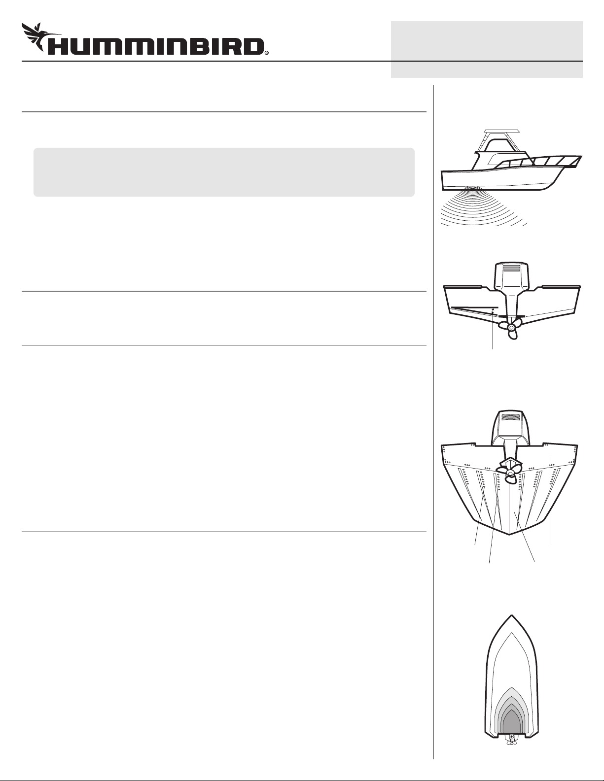
2. Locating the Transducer Mounting Position
Outside the oat, the best location for the transducer will be aft midship, as close to the centerline of the boat as
possible. The transducer should be mounted forward of the propellers on inboard boats, and separated adequately
from other transducers, strakes, rivet lines, or other protrusions. Make sure that there is nothing in front, behind, or to
the side of the transducer that is closer than 12".
WARNING! Do NOT inst ll the tr nsducer in line with the engine int ke.
Inside the oat, there must be room to access the mounting location for installation and cable routing.
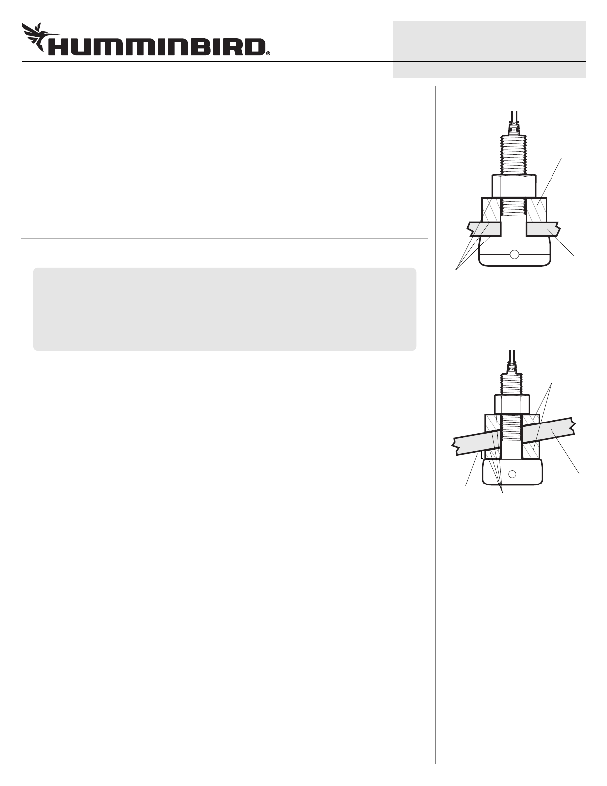
Deadrise: Another consideration is the angle of deadrise. The transducer, when mounted, should point straight down.
If the selected mounting location has a hull deadrise of 8 degrees or more, the included leveling block should be used
to level the transducer housing and direct the sonar signal straight down. If you need to use the leveling block, make
sure that the inside surface of the hull is smooth enough to seat the leveling block securely.
NOTE: If you c nnot find loc tion th t will work for your pplic tion, find different tr nsducer by visiting the FAQ
(Frequently Asked Questions) section of our Web site t humm nb rd.com or by c lling Humminbird Customer Service
t 1-800-633-1468.
NOTE: This type of tr nsducer inst ll tion is not recommended for tr iler ble bo ts.
NOTE: This tr nsducer requires drilling hole in the hull of the bo t; therefore, inst ll tion should be performed by
qu lified m rine technici n.
Thru-Hull Installation
De drise Angle
Preferred Mounting Location
Plastic Thru-Hull Transducer
1
530758-5_B
Areas of Possi le Tur ulence
Rivets Tr nsom
Str kes Hull
Plastic Thru-Hull Transducer
6
530758-5_B
Plastic Thru-Hull Transducer
5
530758-5_B
Re urning Your Uni for Service
Before sending your unit in for repair, please contact the factory, either by
phone or by email, to obtain a Repair Authorization Number for your unit.
NOTE: Ple se do not return your Humminbird to the store for service.
Please have your product model name and serial number available before
calling the factory. If you contact the factory by e-mail, please include your
product model name and serial number in the e-mail, and use Request for
Repair Authorization Number for your e-mail subject header. You should
include your Repair Authorization Number in all subsequent communications
about your unit.
For IN-WARRANTY service, complete the following steps:
• Obtain a Repair Authorization Number from Humminbird Customer
Service.
• Tag product with your name, street address, phone number and your
assigned Repair Authorization Number.
• Include a brief written description of the problem.
• Include a copy of your receipt (to show proof and date of purchase).
• Return product freight prepaid to Humminbird, using an insured carrier
with delivery confirmation.
For OUT-OF-WARRANTY service, complete the following steps:
• Obtain a Repair Authorization Number from Humminbird Customer
Service.
• Include payment in the form of credit card number and expiration date,
or a money order. Please do not send cash.
• Tag product with your name, street address, phone number and your
assigned Repair Authorization Number.
• Include a brief written description of the problem.
• Return product freight prepaid to Humminbird, using an insured carrier
with delivery confirmation.
Con ac Humminbird
We site humminbird.com
Telephone 1-800-633-1468
Direct Shipping Humminbird
Service Department
678 Humminbird Lane
Eufaula, AL 36027 USA
WARNING! This device should not be used s n vig tion l id to prevent
collision, grounding, bo t d m ge, or person l injury. When the bo t is moving,
w ter depth m y ch nge too quickly to llow time for you to re ct. Alw ys oper te
the bo t t very slow speeds if you suspect sh llow w ter or submerged objects.
WARNING! Dis ssembly nd rep ir of this electronic unit should only be performed
by uthorized service personnel. Any modific tion of the seri l number or ttempt to
rep ir the origin l equipment or ccessories by un uthorized individu ls will void the
w rr nty.
WARNING! This product cont ins chemic ls known to the St te of C liforni to
c use c ncer nd birth defects or other reproductive h rm.
ENVIRONMENTAL COMPLIANCE STATEMENT: It is the intention of Johnson
Outdoors M rine Electronics, Inc. to be responsible corpor te citizen, oper ting in
compli nce with known nd pplic ble environment l regul tions, nd good
neighbor in the communities where we m ke or sell our products.
WEEE DIRECTIVE: EU Directive 2002/96/EC “W ste of Electric l nd Electronic
Equipment Directive (WEEE)” imp cts most distributors, sellers, nd m nuf cturers
of consumer electronics in the Europe n Union. The WEEE Directive requires the
producer of consumer electronics to t ke responsibility for the m n gement of w ste
from their products to chieve environment lly responsible dispos l during the
product life cycle.
WEEE compli nce m y not be required in your loc tion for electric l & electronic
equipment (EEE), nor m y it be required for EEE designed nd intended s fixed or
tempor ry inst ll tion in tr nsport tion vehicles such s utomobiles, ircr ft, nd
bo ts. In some Europe n Union member st tes, these vehicles re considered
outside of the scope of the Directive, nd EEE for those pplic tions c n be
considered excluded from the WEEE Directive requirement.
This symbol (WEEE wheelie bin) on product indic tes the product must not
be disposed of with other household refuse. It must be disposed of nd
collected for recycling nd recovery of w ste EEE. Johnson Outdoors
M rine Electronics, Inc. will m rk ll EEE products in ccord nce with the
WEEE Directive. It is our go l to comply in the collection, tre tment, recovery, nd
environment lly sound dispos l of those products; however, these requirements do
v ry within Europe n Union member st tes. For more inform tion bout where you
should dispose of your w ste equipment for recycling nd recovery nd/or your
Europe n Union member st te requirements, ple se cont ct your de ler or
distributor from which your product w s purch sed.
NOTE: Oper tions m nu ls re provided on the CD included with your Humminbird
control he d, or you c n downlo d Humminbird m nu ls from our Web site t
humm nb rd.com.
© 2014 ohnson Outdoors Marine Electronics, Inc. All rights reserved.
Plastic_Thru-Hull_Tra sducer_IG_530758-5_B.qxp:530758-3_B 7/8/14 11:53 AM Page 1