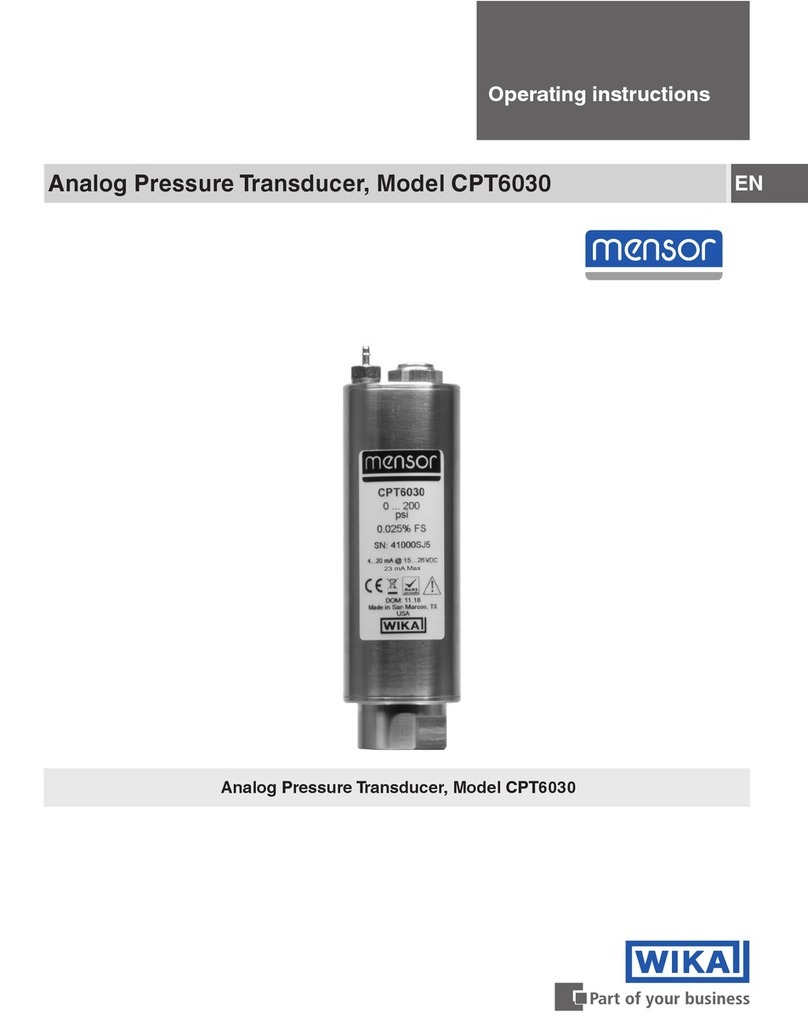
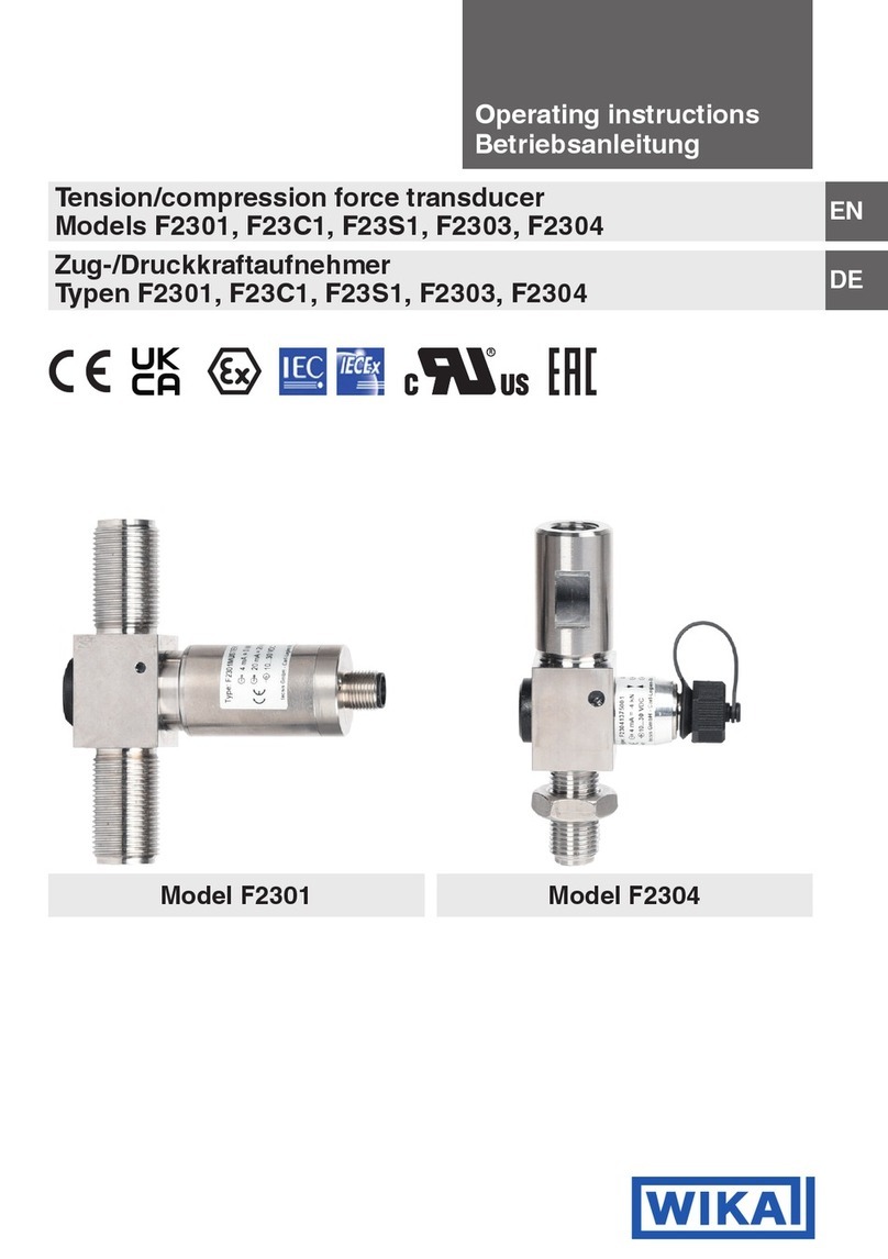
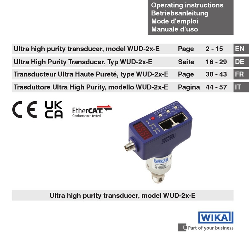
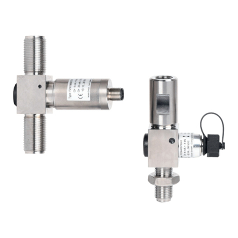
WIKA WUD-20 User manual

11611057.01 GB/D 08/2013
WIKA Alexander Wiegand SE & Co. KG
Alexander-Wiegand-Straße 30
63911 Klingenberg/Germany
Phone +49 93 72/132-8976
Fax +49 93 72/132-8008976
www.wika.de
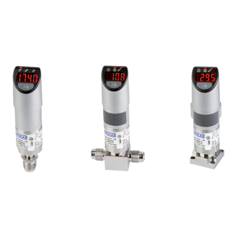
WUD-20
WUD-25
WUD-26
Ultra High Purity
Pressure transducer and integrated
display with optional alarm contacts
Current terms and conditions apply. Details are available
on www.wika.com
Es gelten unsere aktuellen Verkaufs- und
Lieferbedingungen siehe unter www.wika.de
Operating instructions
Betriebsanleitung

Operating instructions/Betriebsanleitung, WUD-2x
11611057.01 GB/D 08/2013
2
Contents, page 3 - 24 GB
1. Important details for your information 3
2. A quick overview for you 4
3. Signs and symbols 4
4. Function 5
5. For your safety 5
6. Packaging 6
7. Initial start-up and operation 7
8. Adjustment of zero point 20
9. Maintenance, accessories 21
10. Trouble shooting 21
11. Storage, disposal 23
12. Declaration for conformity 24
Inhalt, Seite 25 - 48 D
1. Wichtiges zu Ihrer Information 25
2. Der schnelle Überblick für Sie 26
3. Zeichenerklärungen, Abkürzungen 26
4. Funktion 27
5. Zu Ihrer Sicherheit 27
6. Verpackung 28
7. Inbetriebnahme, Betrieb 29
8. Einstellung Nullpunkt 42
9. Wartung, Zubehör 43
10. Störbeseitigung 43
11. Lagerung, Entsorgung 45
12. EG Konformitätserklärung 47
GB
Contents

11611057.01 GB/D 08/2013
3
Operating instructions/Betriebsanleitung, WUD-2x
1. Important details for your information / 2. A quick overview for you GB
Read these operating instructions without fail before installing and starting the pressure transducer WUD-2x.
1. Important details for your information
Read these operating instructions before installing and starting the pressure transducer. Keep the operating instructions in
a place that is accessible to all users at any time.
The following installation and operating instructions have been compiled by us with great care but it is not feasible to take
all possible applications into consideration.These installation and operation instructions should meet the needs of most
pressure measurement applications. If questions remain regarding a specic application, you can obtain further information:
■
Via our Internet address www.wika.de / www.wika.com
■
The product data sheet is designated as PE 87.08
■
Contact WIKA for additional technical support (+49) 9372 / 132-8976
If the serial number on the product label becomes illegible (e.g. by mechanical damage or repainting), the traceability of the
instrument is not possible any more.
WIKA's pressure transducers WUD-2x are carefully designed and manufactured using state-of-the-art technology. Every
component undergoes strict quality and environmental inspection before assembly and each instrument is fully tested prior
to shipment. Our environmental management system is certied to DIN EN ISO 14001.
Knowledge required: Install and start the pressure transducer only if you are familiar with the relevant regulations and direc-
tives of your country and if you have the qualication required. Depending on the operating conditions of your application
you have to have the corresponding knowledge, e.g. of aggressive media.
2. A quick overview for you
If you want to get a quick overview, read Chapters 3, 5, 7 and 11.There you will get some short safety instructions and
important information on your product and its starting. Read these chapters in any case.

Operating instructions/Betriebsanleitung, WUD-2x
11611057.01 GB/D 08/2013
4
WARNING!
Potential danger of life or of severe injuries.
Notice, important information, malfunction. The product complies with the applicable
European directives.
3. Signs and symbols / 4. Function /
WARNING!
Potential danger of life or of severe injuries due
to catapulting parts.
CAUTION!
Potential danger of burns due to hot surfaces.
3. Signs and symbols
Direct voltage
GB
U+ Positive supply connection
U- Negative supply connection
SP1 Switching point 1 (optional)
SP2 Switching point 2 (optional)
S+ Analogue output
3-wire Two connection lines are intended for the voltage supply.
One connection line is intended for the measurement signal.
4. Function
Ultra High Purity pressure transducer and integrated display
WUD-20: Single End
WUD-25: Flow Through
WUD-26: Modular Surface Mount
Function: The pressure prevailing within the application is transformed into a switching output or standardised electrical
signal through the deection of the diaphragm, which acts on the sensor element with the power supply fed to the instru-
ment.This electric signal and the indication changes in proportion to the pressure and can be evaluated correspondingly.

11611057.01 GB/D 08/2013
5
Operating instructions/Betriebsanleitung, WUD-2x
5. For your safety
5. For your safety
WARNING!
■
Select the appropriate pressure transducer with regard to scale range, performance and specic measure-
ment conditions prior to installing and starting the instrument.
■
Consider the relevant national regulations (e.g.: EN/IEC 60079-14) and observe the applicable standards
and directives for special applications (e.g. with dangerous media such as acetylene, ammable gases or
liquids and toxic gases or liquids and with compressors). Non-observance can result in serious injury and/or
damage to equipment.
■
Open pressure connections only after the system is without pressure!
■
Please make sure that the pressure transducer is only used within the overload threshold limit all the time!
■
Observe the ambient and working conditions outlined in chapter 7 "Initial start-up and operation".
WARNING!
■
Ensure that the pressure transducer is only operated in accordance with the provisions i.e. as described in
the following instructions.
■
Do not interfere with or change the pressure transducer in any other way than described in these operating
instructions.
■
Remove the pressure transducer from service and mark it to prevent it from being used again accidentally, if
it becomes damaged or unsafe for operation
■
Take precautions with regard to remaining media in removed pressure transducer. Remaining media in the
pressure port may be hazardous or toxic!
■
Have repairs performed by the manufacturer only.
■
The operator is responsible for the material compatibility as well as correct handling, operation and mainte-
nance.
Information about material consistency against corrosion and diusion can be found in our WIKA-Handbook, 'Pressure and
Temperature Measurement'.
GB

Operating instructions/Betriebsanleitung, WUD-2x
11611057.01 GB/D 08/2013
6
6. Packaging / 7. Initial start-up and operation
6. Packaging
Has everything been supplied?
Check the scope of supply:
■
Completely assembled pressure transducer
■
Inspect the pressure transducer for possible damage during transportation. Should there be any obvious
damage, inform the transport company and WIKA without delay.
■
The WIKA's UHP pressure transducers are puried, evacuated and double-packed in clean rooms in a
protective atmosphere (clean room class 5 according to ISO 14644). Special plastic protective caps are
used to protect the high-quality threaded connections (ttings). The pressure transducers should remain in
this special packaging until installation in order to prevent damage and contamination.Therefore remove the
ESD (Electro-Static-Discharge) protective foil only at the place of installation.
■
Keep the packaging, as it oers optimal protection during transportation (e.g. changing installation location,
shipment for repair).
■
Ensure that the pressure connection thread and the connection contacts will not be damaged.
■
Remove this protection cap only just before installing the pressure transducer.
■
Mount the protection cap when removing and transporting the instrument.
Unpacking the pressure transducer and integrated display
1. Remove the pressure transducer from the box.
2. Remove the outer protective bag and discard.
3. Carry the pressure transducer (sealed in the inner bag), into the clean area.
7. Initial start-up and operation
■
For indoor use only.
■
Required tools: wrench (ats 19 and 16), screw driver (0.040" to 0.060" / 1 to 1.5 mm) and a pair of scissors,
allen key for WUD-26
GB

11611057.01 GB/D 08/2013
7
Operating instructions/Betriebsanleitung, WUD-2x
7. Initial start-up and operation
Mechanical connection Product label (example)
Coded manufacture
date
Use this spanner at for screwing in!
Don't use this spanner at!
P# Product No.
S# Serial No.
PIN assignment
Signal
Power Supply
GB
■
Remove the protection cap only just before installation.
■
When mounting the instrument, ensure that the sealing faces of the instrument and the measuring point are
clean and undamaged.
■
Do not scratch or nick the bead. Do not over tighten. Damage to the bead will aect the tting's performance
and may cause leakage in the system.
■
Screw in or unscrew the instrument only via the ats using a suitable tool and the prescribed torque. The
appropriate torque depends on the dimension of the pressure connection and on the sealing element used
(form/material). Do not use the case as working surface for screwing in or unscrewing the instrument.
■
When screwing the pressure transducer in, ensure that the threads are not jammed.
Mechanical Connection
■
Prepare the gas line connections appropriately.
■
You should blow clean all tting components (such as sealing gaskets, for example) using a clean/ltered gas. Please
refer to the specic technical guides furnished by the gasket manufacturers for additional specications.
■
You can then remove the protective lm, as well as any plastic caps there may be for protecting high-quality ttings.

Operating instructions/Betriebsanleitung, WUD-2x
11611057.01 GB/D 08/2013
8
7. Initial start-up and operation
Face Seal Connections (only WUD-20, WUD-25)
For connections compatible with face seal-ttings:
1. Hold the swivel female face seal / swivel male face seal, mounting part (valve etc.) or case hexagon.Tighten the swivel
female face seal hand-tight and adjust the instrument to the desired position. When tightening or untightening at mount-
ing parts (valves etc.) or ttings, ensure that the threads do not get jammed.
2. Hold the swivel female face seal with a suitable open-end wrench.Tighten the swivel female face seal / swivel male face
seal or mounting part (valve etc.) by a 1/8 or 1/4 turn (depending on the sealing elements used) beyond the hand-tight
position.
3. Please refer to the specic technical guides furnished by the tting manufacturers for additional specications.
4. With that the pressure transducer is mechanically connected. Electrical connection possibilities are described in the
following chapter.
Welding Connections (only WUD-20, WUD-25)
The weld needs to be fully penetrated, but amperage and heat need to be minimised. We recommend owing Argon gas
through the pressure transducer during welding. This will help to cool the pressure transducer. Prior to welding tubing to the
pressure transducer, it is recommended that a few test welds be made.
WARNING!
■
Make sure the pressure transducer is not connected to any other device, prior to arc welding.
■
Disconnect the pressure transducer from any electrical device.
■
The operator is responsible for the material compatibility as well as correct handling, operation and mainte-
nance.
Prepare the pressure transducer for use
1. Adjust the zero point (please refer to chapter 8 "Adjustment of zero point").
2.Verify integrity of the weld or seal by appropriate helium leak-testing procedures.
3. Turn the gas ow ON then OFF, 10 times to remove any particles generated during installation. (The ow rate used should
at least equal the process ow specications.)
4.Optionally you have to set the switch points (please refer to page 18).
MSM, Modular Surface Mount (only WUD-26)
Please observe the corresponding technical specications, such as torques and mounting position of the contact components.
GB

11611057.01 GB/D 08/2013
9
Operating instructions/Betriebsanleitung, WUD-2x
7. Initial start-up and operation
Electrical connection
WARNING!
Connect the enclosure to ground through the process connection, against electromagnetic elds and electro-
static discharge.
■
Use only shielded cables. Note that with connectors no connection between cable shield and housing is
possible. For instruments with cable outputs, the cable is always shielded. Depending upon the design
(ordered version) the screen may or may not be connected with the enclosure. An additional equipotential
bonding maybe required.
■
Ensure that the cable diameter you select ts to the cable gland of the connector Ensure that the cable gland of
the mounted connector is positioned correctly and that the sealings are available and undamaged.Tighten the
threaded connection and check the correct position of the sealings in order to ensure the ingress protection
■
Cover ying leads with ne wires by an end splice (cable preparation).
■
Please make sure that the ends of cables with ying leads do not allow any ingress of moisture.
■
The pressure transducer must be connected and operated in accordance with the approriate regulations.
Take care to ensure that the electrical connection (e.g. M12 connector) is correctly made (fully sealed).
WIKA's pressure transducers are designed to operate with an input voltage of DC 10 ... 30 V for output signals 4 ... 20 mA
and 0,5 V / DC 14 ... 30 V for output signal 0 ... 10 V. The interrelationship between voltage supply and load resistor (RA) is
illustrated by the following diagram.
Signal output and allowed load
GB
Current output (3-wire)
4 ... 20 mA:
RA≤(U+ – 10 V) / 0,02 A
Voltage output (3-wire)
0 ... 5 V: RA> 5 kOhm
0 ... 10 V: RA> 10 kOhm
with RAin Ohm and U+in Volt
permitted range
4 ... 20 mA, 3-wire

Operating instructions/Betriebsanleitung, WUD-2x
11611057.01 GB/D 08/2013
10
Wiring details
Bayonet connector, 4-pin Circular connector M12x1,
4-pin
Circular connector M12x1,
5-pin
Flying leads, 1.5 m or 3 m
43
12
3-wire U+ = A U- = D S+ = B U+ = 1 U- = 3 S+ = 4 U+ = 1 U- = 3 S+ = 4 U+ = red U- = black S+ = brown
Switching outputs SP1 = 2 SP1 = 2, SP2 = 5 SP1 = blue, SP2 = white
Wire gauge - - - 0.22 mm2(AWG 24)
Diameter of cable - - - 4.8 mm
Ingress protection
per IEC 60529
IP 67 IP 67 IP 67 IP 65
The ingress protection classes specied only apply while the pressure transmitter is connected with female connectors
that provide the corresponding ingress protection.
Wiring details
Sub-D HD connector, 15-pin
3-wire U+ = 7 U- = 5
U- = 12
S+ = 2
Switching outputs SP1 = 14, SP2 = 13
Wire gauge -
Diameter of cable -
Ingress protection
per IEC 60529
IP 20
The ingress protection classes specied only apply while the pressure transmitter is connected with female connectors
that provide the corresponding ingress protection.
7. Initial start-up and operation GB

11611057.01 GB/D 08/2013
11
Operating instructions/Betriebsanleitung, WUD-2x
Specications Models WUD-20, WUD-25 and WUD-26
WUD-20, WUD-25
WUD-26
Pressure ranges psi 14.5 25 60 100 160 250 350 500 1,000 1,500
bar 1 1.7 4 7 11 17 25 36 70 100
Over pressure safety 1) psi 120 120 120 210 320 500 750 1,100 2,100 3,000
Burst pressure 1) psi 1,800 1,800 1,800 2,200 2,600 4,800 6,200 5,800 8,000 10,500
Pressure ranges psi 2,000 3,000 5,000
bar 145 225 360
Over pressure safety 1) psi 4,200 6,600 10,500
Burst pressure 1) psi 10,500 10,500 12,000
Other pressure ranges, pressure units (e.g. MPa, kg/cm2) on request
Absolute pressure: 0...2 bar to 0...60 bar, Vacuum pressure: -1...1 bar to -1...250 bar
Measuring principle Metal thin-lm sensor
Materials
■
Wetted parts
- Pressure connection 316L VIM/VAR
- Pressure sensor 2.4711 / UNSR 30003
■
Case
- Lower body 304 SS
- Plastic components PBT
- Keyboard TPE
- Display cap PC
Particle test ≤ 0.1 µm Particle 0.1 ptc / ft3according to Semi E49.8
Inboard helium leak test < 1 x 10⁻⁹ mbar l/sec (atm STD cc/sec) according to Semi F1
Surface nish
Electropolished, typical Ra ≤ 0.13 µm (RA 5); max. Ra ≤ 0.18 µm (RA 7)
according to Semi F19
Dead volume WUD-20 < 1.5 cm3, WUD-25 < 1 cm3, WUD-26 < 1 cm3
Permissible medium Special gas, vapour, liquid
1) 1 psi = 0.069 bar
7. Initial start-up and operation GB

Operating instructions/Betriebsanleitung, WUD-2x
11611057.01 GB/D 08/2013
12
Specications Models WUD-20, WUD-25 and WUD-26
Power supply U+DC 10 ... 30 V with output signal 4 ... 20 mA / DC 0 ... 5 V
DC 14 ... 30 V with output signal DC 0 ... 10 V
Signal output and maximum
ohmic load RA (in Ω)
4 … 20 mA, 3-wire, RA≤ (U+ – 10 V) / 0.02 A
DC 0 ... 5 V, 3-wire, RA> 5 k
DC 0 ... 10 V, 3-wire, RA> 10 k
Power Pi1 W
Current consumption max. 50 mA
Total current supply max. 250 mA (incl. switching current)
Adjustability zero -3.5 ... +3.5 % of span (via potentiometer), current output signal
-2 ... +3.5 % of span (via potentiometer), voltage output signal
Signal response (10 ... 90 %) ≤ 300 ms
Switch points individually adjustable via external control keys
■
Type transistor switching output NPN
■
Number 1 or 2
■
Function normally open, normally closed, on, o
■
Switching current Max. current that can be used with the switch
SP1: 100 mA
SP2: 100 mA
■
Accuracy ≤ 0.5 % of span
Insulation voltage DC 500 V
Display
■
Design 7 segment-LED, red, 4-digits, height 8 mm, electronic 180° rotatable
■
Accuracy ≤ 1.0 % of span ±1 Digit
■
Update 0.2 / 0.5 / 1 / 5 / 10 / 60 sec (adjustable)
Accuracy ≤ 0.15 % of span (≤ 0.4 with pressure ranges ≤ 2 bar) RSS (Root Sum Squares)
≤ 0.3 % 1) of span (≤ 0.6 1) with pressure ranges ≤ 2 bar)
Non-linearity ≤ 0.1 % of span (≤ 0.15 for pressure ranges ≤ 2 bar) (BFSL) according to IEC 61298-2
Hysteresis ≤ 0.14 % of span
Non-repeatability ≤ 0.12 % of span
1-year stability ≤0.25 % of span typ.(at reference conditions)
1) Including non-linearity, hysteresis, zero point and full-scale error (corresponds to error of measurement per IEC 61298-2)
7. Initial start-up and operation GB

11611057.01 GB/D 08/2013
13
Operating instructions/Betriebsanleitung, WUD-2x
Specications Models WUD-20, WUD-25 and WUD-26
Permissible temperature of
■
Medium -20 ... +100 °C / -4 ... +212 °F
■
Ambience -10 ... +60 °C / 14 ... 140 °F
■
Storage -10 ... +60 °C / 14 ... 140 °F
Rated temperature range -20 ... +80 °C / -4 ... +176 °F (active compensated)
Temperature coecients within
rated temperature range
(active compensated)
■
Mean TC of zero ≤0.10 % of span / 10 K
■
Mean TC of range ≤0.15 % of span / 10 K
RoHS-conformity Yes
CE- conformitiy
■
Pressure equipment directive 97/23/EC
■
EMC directive 2004/108/EC, EN 61 326 Emission (Group 1, Class B) and Immunity (industrial locations)
Assembly and packing area Clean room class 5 according to ISO 14644
Packaging Double bagging according to SEMI E49.6
Shock resistance 40 g SEMI F69-0302/MIL-STD 810 Part 2, 500 g labory test method 516.5, procedure 1, sawtooth shock
Vibration resistane MIL-STD 812 Part 2, labory test method 514.5, procedure 1, category 4
Wiring protection
■
Short-circuit proofness S+towards U-
■
Reverse polarity protection U+towards U-
Weight Approx. 0.2 kg
7. Initial start-up and operation
When designing your plant, take into account that the stated values (e.g.burst pressure, over pressure safety)
apply depending on the material, thread and sealing element used.
GB

Operating instructions/Betriebsanleitung, WUD-2x
11611057.01 GB/D 08/2013
14
Functional test
The output signal must be proportional to the pressure. If not, this might point to a damage of the diaphragm. In
that case refer to chapter 10 „Trouble shooting“.
WARNING!
■
Open pressure connections only after the system is without pressure!
■
Observe the ambient and working conditions outlined in chapter 7 "Initial start-up and operation".
■
Please make sure that the pressure transducer is only used within the over load threshold limit at all times!
Menu One Key Version (without optional alarm contacts)
Operating-Mode
dISu short press long press to conrm setting
(seconds)
Toggle values
by short press
(relevant LED lights up)
The switch returns to the operating mode, if no key is pressed within 1 minute.
short press
long press
extra long press
(10 seconds)
Toggle units
by short press
psia MPa bar units may vary
Rotate display
by 180°
DISU = Display Update
0.2
0.5
1
5
10
60
7. Initial start-up and operation GB

11611057.01 GB/D 08/2013
15
Operating instructions/Betriebsanleitung, WUD-2x
7. Initial start-up and operation
Keys and functions (optional alarm contacts)
Operating mode Programming mode
Main key short press:
- Select menu item
- Conrmation of setting (Parameter value)
long press:
- Rotate display by 180°
long press:
- Select menu item
- Conrmation of setting (Parameter value)
Down key short press:
- Menu down
- Decrease parameter value
long press:
Switch to programming mode
long press:
- Menu down
- Decrease parameter value
Up key short press:
- Menu up
- Increase parameter value
long press:
- Menu up
- Increase parameter value
Up and Down key -short press (both keys at the same time):
Return to operating mode
GB

Operating instructions/Betriebsanleitung, WUD-2x
11611057.01 GB/D 08/2013
16
1. LED (red) - Status Switch Output 1
2. LED (red) - Status Switch Output 2
3. LED (red) - Ready LED
Parameter
Parameter Description
SP1 / SP2 Hysteresis function: Switch point, switch output (1 or 2)
RP1 / RP2 Hysteresis function: Reset point, switch output (1 or 2)
EF Enhanced Programming Functions
RES Return the set parameter to the Factory Settings
DS1 Switch Delay Time, which must occur without interruption before any electrical signal change occurs (SP1 or SP2)
DS2
DR1 Switch Delay Time, which must occur without interruption before any electrical signal change occurs (RP1 or RP2)
DR2
OU1 Switching Function Switching Output (1 or 2)
OU2 OFF = always o
ON = always on
NO = normally open
NC = normally closed
DISU Display-Update 0.2, 0.5, 1, 5, 10, 60 seconds
DISO Display zero point oset (± 10 % of full scale)
(This setting has no eect on the ouput signal. Only the displayed value will be set.)
Error Display
Error Description
ATT Setting out of range (Acknowledgement of an error display by pressing the main key)
OL Overpressure, measuring range exceeded > approx. 5% (Display ashing)
UL Underpressure, under measuring range < approx. 2% (Display ashing)
7. Initial start-up and operation GB

11611057.01 GB/D 08/2013
17
Operating instructions/Betriebsanleitung, WUD-2x
Menu (programming and factory setting)
Operating mode
Long press on down key
Programming mode Factory setting:
SP1 Value (Min: MBA +0.5 % Max: MBE) 60 % of instrument nominal pressure
RP1 Value (Min: MBA Max: SP1 -0.5 %) 40 % of instrument nominal pressure
SP2 1) Value (Min: MBA +0.5 % Max: MBE) 60 % of instrument nominal pressure
RP2 1) Value (Min: MBA Max: SP2 -0.5 %) 40 % of instrument nominal pressure
EF RES Yes / No Reset to factory setting
DS1 Value 0 ... 50 s 0 s
DR1 Value 0 ... 50 s 0 s
DS2 1) Value 0 ... 50 s 0 s
DR2 1) Value 0 ... 50 s 0 s
OU1 PARA OFF, ON, NO, NC NO
OU2 1) PARA OFF, ON, NO, NC NO
DISU Value 0.2, 0.5, 1, 5, 10, 60 seconds 0.2 s
DISO Value (± 10 % of full scale) 0%
Legend:
MBA = Start of measuring range
MBE = End of measuring range
1) Only available for instruments with two switching outputs
END END
Operating mode
7. Initial start-up and operation
The switch returns to the operating mode, if no key is pressed within 1 minute.
GB

Operating instructions/Betriebsanleitung, WUD-2x
11611057.01 GB/D 08/2013
18
Switch function
Hysteresis function
If the system pressure uctuates around the set point, the hysteresis keeps
the switching status of the outputs stable.With increasing system pressure,
the output switches when reaching the switch point (SP).
■
Contact normally open (NO): active
■
Contact normally closed (NC): inactive
With system pressure falling again, the output will not switch back before the
reset point (RP) is reached.
■
Contact normally open (NO): inactive
■
Contact normally closed (NC): active
Delay times (0 ... 50 s)
This makes it possible to lter out unwanted system pressure peaks of a short
duration or a high frequency (damping).The system pressure must be present
for at least a certain pre-set time for the output to switch on.The output does
not immediately change its status when it reaches the switching event (SP),
but rather only after the pre-set delay time (DS).
If the switching event is no longer present after the delay time, the switch
output does not change.The output only switches back when the system
pressure has fallen down to the reset point (PR) and stays at or below the
reset point (RP) for at least the pre-set delay time (DR).
If the switching event is no longer present after the delay time, the
switch output does not change.
7. Initial start-up and operation GB

11611057.01 GB/D 08/2013
19
Operating instructions/Betriebsanleitung, WUD-2x
8. Adjustment of zero point
The WUD-2x pressure transducers are maintenance free. All WIKA pressure transducers are factory calibrated and under
normal operating conditions will not require eld adjustment.
For verication and adjustment of the zero point, vent the pressure transducer to zero (0) psi for gauge
reference
pressure
transducers
. Use a 0.040" to 0.060" (1 to 1.5 mm) jeweler's screwdriver for adjustment.
■
For instruments with absolute pressure measuring ranges or +/- measuring ranges, a sucient calibration
equipment as well as a vacuum pump are also necessary for the zero point adjustment.
■
Span adjustment is not necessary after zero point correction.
8. Adjustment of zero point GB
Procedure
1. Restore power to the pressure transducer.
2. Lift the sticker.
3. Adjust the zero point by means of the potentiometer in pressureless state.
Check the zero point by means of a suiable instrument. Clockwise rotation
means an upward zero oset, anti-clockwise rotation means a downward zero
oset.
4. Push the sticker on.
For further information
(+49) 9372/132-8976

Operating instructions/Betriebsanleitung, WUD-2x
11611057.01 GB/D 08/2013
20
9. Maintenance, accessories / 10. Trouble shooting
9. Maintenance, accessories
■
WIKA's pressure transducers require no maintenance.
■
Have repairs performed by the manufacturer only.
Accessories: For details about the accessories (e. g. connectors), please refer to WIKA‘s price list, WIKA‘s product catalog
on CD or or contact our sales department.
10. Trouble shooting
WARNING!
Open pressure connections only after the system is without pressure!
WARNING!
■
Take precautions with regard to remaining media in removed pressure transducers. Remaining media in the
pressure port may be hazardous or toxic!
■
Remove the pressure transducer from service and mark it to prevent it from being used again accidentally, if
it becomes damaged or unsafe for operation. Have repairs performed by the manufacturer only.
Do not insert any pointed or hard objects into the pressure port for cleaning to prevent damage to the
diaphragm of the pressure connection.
Please verify in advance if pressure is being applied (valves/ ball valve etc. open) and if the right voltage supply and the
right type of wiring (3-wire) has been chosen?
Failure Possible cause Procedure
Output signal unchanged after change in
pressure
Mechanical overload through overpressure Replace instrument; if failure reoccurs, consult
the manufacturer *)
Wrong supply voltage Replace instrument
No output signal No/incorrect voltage supply or current spike Adjust the voltage supply according to the
operating instructions *)
Cable break Check connections and cable
GB
Other manuals for WUD-20
1
This manual suits for next models
2
Table of contents
Languages:
Other WIKA Transducer manuals
Popular Transducer manuals by other brands

HK Instruments
HK Instruments DPT-R8 Series installation instructions

Setra Systems
Setra Systems GCT225 installation guide

Swagelok
Swagelok S user manual

Fluke
Fluke PV350 Quick reference guide

MKS
MKS UniMag 971 Operation and installation manual

Desoutter
Desoutter Industrial Tools ART 4H5 User instructions

M-system
M-system BPV instruction manual

PCB Piezotronics
PCB Piezotronics 2302-110-02A Installation and operating manual

Badger Meter
Badger Meter Dynasonics TFX-500w installation guide

bk ultrasound
bk ultrasound 8816 user guide

Enerdis
Enerdis TRIAD 2 User & installation manual

Gems
Gems 2200 Series Operating & installation instructions