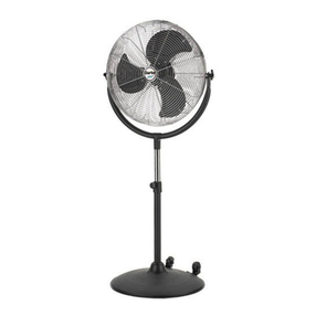
Hunter 9015x User manual

42729-01 12/20/2006
ENGLISH
See page 1
ESPAÑOL
Vea la página 15
FRANÇAIS
Consulter la page 29
OWNER’S GUIDE
FOR MODELS 9015X & 9017X
SUMMER BREEZE
Collection
Indoor/Outdoor Pedestal Fan
The

242729-01 12/20/2006
ENGLISH
Important Safety InformatIon
Read & Save These Instructions
CautIon
When using electrical appliances, basic
precautions should always be taken to
reduce the risk of fire, electric shock
and personal injury:
1. Read all instructions before using
this fan.
2. Improper assembly may result in
the risk of fire, electric shock or
personal injury.
3. The power plug must be removed
from the power socket when not
in use, before cleaning, servicing,
maintenance and before moving to
another location.
4. Place the fan on a flat, dry, stable
surface to avoid tipping over.
5. Use fan only for intended use,
as described in this instruction
manual.
6. To protect against electrical shock,
use fan with only GFCI protected
receptacles when using the fan in
damp or outdoor locations.
7. NEVER insert fingers, pencils
or any other objects through
the grille.
8. DO NOT operate this fan:
• if the cord is damaged
• if the fan malfunctions
• if the fan has been dropped or
damaged in any way
9. To disconnect, grip plug and pull
from wall outlet. NEVER yank on
cord.
10. This product is intended for house-
hold use only and not for commer-
cial or industrial use.
11. DO NOT operate fan in the pres-
ence of explosive and/or flam-
mable fumes.
12. DO NOT place fan or any parts
near an open flame, cooking or any
other heating appliances.
13. DO NOT use near curtains, plants,
window treatments, etc.
14. Never operate the fan if the grills
are not properly installed. Operat-
ing the fan without the grills could
result in serious injury.
15. The appliance is not intended for
use by young children or infirm
persons without supervision.
Young children should be super-
vised to ensure that they do not
play with the appliance.
16. This appliance has a grounded
three-prong plug and is suitable
for grounded receptacle use only.
An adapter is available for con-
necting three-blade grounding-
type plugs to two-slot receptacles.
The adapter must be properly
grounded. DO NOT attempt to
defeat the purpose of this safely
feature.

42729-01 12/20/2006 3
ENGLISH
Please attach your
receipt or a copy of your
receipt to this manual
for future reference.
WelCome unpaCkIng
Thank you for choosing a Hunter
Pedestal Fan. This manual gives you
complete instructions for using your
fan. Here are some the features you
will enjoy with your fan:
• An attractive design that enhances
any decor
• A powerful Hunter motor for max-
imum air flow
• Three speeds to adjust your com-
fort level
Before using your fan, record the fol-
lowing information for your records
and for warranty assistance.
Model Name____________________
Date Code _____________________
Date Purchased _________________
Where Purchased________________
_______________________________
As you unpack the fan, save the
carton and packing materials in case
you want to move or ship the unit in
the future.
Carefully remove all items from
the box.
NOTE: It is best to have someone
hold the box while you lift the fan
and the protective packaging out of
the carton.
Make sure all shipping materials are
removed from fan before operating.
TOOLS NEEDED
• Adjustable wrench
• Phillips screwdriver

442729-01 12/20/2006
ENGLISH
This appliance is for household use
only and may be plugged into any
120-volt AC electrical outlet (or-
dinary household current). DO NOT
use any other type of outlet.
The power cord has a grounded plug
as shown in Figure 1A. The fan must
be plugged into an electrical outlet
that can accommodate the ground-
ing pin. If your electrical outlet can
not accommodate the grounding
pin, then you must purchase and in-
stall one of the two types of adapt-
ers shown in Figure 1B.
groundIng InStruCtIonS
FIGURE 1B
FIGURE 1A
Grounded Outlet
Box Cover
Grounded
Plug
Grounding Pin
GFCI Tag
Grounded Outlet
Box Cover
Metal
Screw
Adapter
Grounding
Means
WarnIng
GFCI Receptacle
Grounded
Plug
Grounding Pin
GFCI Tag
FIGURE 1C
If this fan is to be used outdoors
or in a damp or wet location, then
it must be plugged into a Ground
Fault Circuit Interrupter (GFCI) re-
ceptacle.
WarnIng
To reduce the risk of fire or
electric shock, do not use this
fan with any solid-state speed
control device.
When the fan is used outdoors or in
a damp or wet location, it must be
plugged into a Ground Fault Circuit
Interruptor (GFCI) receptacle. See
Figure 1C.
WarnIng
This unit is suitable for ground-
ed receptacle use only.

42729-01 12/20/2006 5
ENGLISH
aSSembly
LINE CORD SAFETY TIPS
1. NEVER pull or yank on the cord
or the appliance.
2. To insert plug, grasp it firmly
and guide it into the outlet.
3. To disconnect the appliance,
grasp the plug and remove it
from the outlet.
4. Before each use, inspect the line
cord for cuts and/or abrasion
marks. If any are found, the ap-
pliance should be serviced and
the line cord replaced. Please
return it to our Service Depart-
ment or to an authorized service
representative.
5. NEVER wrap the cord tightly
around the appliance, as this
could place undue stress on the
cord where it enters the appli-
ance and could cause it to fray
and break.
6. DO NOT operate appliance if
the line cord shows any dam-
age, if the appliance works
intermittently or stops working
entirely.
7. DO NOT use an extension cord
with this fan.
note: Assembly of this fan will
be easier if performed by two
people.
1. Slide the Cover Support Cap
over the bottom of the Tele-
scoping Pole. See Figure 1.
FIGURE 1
Telescoping Pole
Cover Support Cap
Base Cover
Pole Setscrew
(pre-installed,
tagged)
Cast
Iron
Base
2. Insert the bottom of the Tele-
scoping Pole through the Base
Cover. See Figure 1.
3. Place the bottom of the Tele-
scoping Pole into the Cast Iron
Base, making sure the plug con-
nector from the bottom of the
Telescoping Pole goes through
the Cast Iron Base. Twist the
Telescoping Pole clockwise to
secure it into the Cast Iron Base.
4. Locate the Pole Setscrew (pre-
installed, tagged) in the neck of
the Cast Iron Base. See Figure 1.
5. Use an adjustable wrench to
tighten the Pole Setscrew (pre-
inserted, tagged) until it seats
firmly against the Telescoping
Pole. See Figure 1.
1. For Model 9017X, remove the
plastic sleeve from the bottom
of the Telescoping Pole.
preparatIon

642729-01 12/20/2006
ENGLISH
aSSembly ContInued
6. Lower the Base Cover over the
Cast Iron Base. See Figure 1.
7. Twist the Cover Support Cap
clockwise into the Cast Iron
Base until it is tight. See Figure
1.
8. Carefully lean the entire assem-
bly over so it rests on its side on
the floor.
9. Remove one of the four Cover
Assembly Screws from the bot-
tom of the Cast Iron Base and
loosen the three remaining Cov-
er Assembly Screws. See Figure
2.
Electrical
Cover Cover Assembly Screw
Telescoping Pole
Base
Wall
Plug
FIGURE 2
Keyslots
10. Connect the plugs coming from
the bottom of the Telescoping
Pole and the insdie of the Elec-
trical Cover.
11. Place the Electrical Cover
against the bottom of the Cast
Iron Base and align the Keyslots
in the Electrical Cover with the
three loosened Cover Assembly
Screws. Rotate the Electrical
Cover counterclockwise. See
Figure 2.
12. Install the fourth Cover Assem-
bly Screw. Tighten all four Cover
Assembly Screws to attach the
Electrical Cover to the bottom
of the Cast Iron Base.

42729-01 12/20/2006 7
ENGLISH
13. Hold the wall plug out of the
way and stand the fan upright.
14. Loosen the Height Adjustment
Grip on the Telescoping Pole by
turning it counterclockwise. See
Figure 3. Raise theTelescoping
Pole approximately 10 inches.
Turn the Height Adjustment
Grip clockwise to set the height
of the Telescoping Pole.
15. Remove the Motor Mount Set-
screw (pre-loaded and tagged)
and set it aside for later reinstal-
lation. See Figure 3.
FIGURE 4
FIGURE 3
Height
Adjustment
Grip
Fan
Motor
Motor
Face
Motor Mount
Setscrew
(pre-loaded
and tagged)
Telescoping
Pole
Back
Grille
Blade
Assembly
Front
Grille Grille
Ring
Interlock Bracket
Motor
Mount
16. Connect the plugs coming from
the bottom of the Motor Mount
and the top of the Telescoping
Pole. See Figure 4.

842729-01 12/20/2006
ENGLISH
aSSembly ContInued
Upper Left Grille
Mounting Screw
FIGURE 5
Flat Portion
Motor Shaft
Grille Mounting Screws
17. Insert the threaded portion of
the Telescoping Pole into the
Motor Mount. See Figure 3.
Turn the Fan Motor to tighten
the joint, then re-install the Mo-
tor Mount Setscrew to secure
the Fan Motor to the Telescop-
ing Pole.
18. Remove the upper left Grille
Mounting Screw from the Mo-
tor Face. See Figure 5. Loosen
the three remaining Grille
Mounting Screws.
Fan Motor
Hole in Motor Face
Interlock Bracket
FIGURE 6
ATTENTION: This fan has a
built-in safety switch that will
not allow the fan to operate
unless the Interlock Bracket is
properly installed, the Grille is
fully assembled to the Motor
Face, and the Interlock Bracket
is secured into place.
19. Install the Interlock Bracket as
shown in Figure 6. NOTE: DO
NOT remove the rubber bar-
rier from the hole in the Motor
Face. Insert the bottom of the
Interlock Bracket into the open-
ing protected by the rubber bar-
rier.

42729-01 12/20/2006 9
ENGLISH
20. Align the three keyhole slots in
the Back Grille with the three re-
maining Grille Mounting Screws
in the Motor Face, and place the
Back Grille onto the Motor Face,
ensuring that the Grille Mount-
ing Screw washers are between
the screw head and the Back
Grille. If necessary, loosen the
three remaining Grille Mounting
Screws. See Figure 7.
21. Rotate the Back Grille clockwise
to situate the screws in the nar-
row ends of the keyhole slots.
22. Reinstall and tighten the Up-
per Left Grille Mounting Screw
and tighten the remaing three
remaining Grille Mounting
Screws.
FIGURE 7
Blade
Assembly
Sleeve
Blade
Assembly
Setscrew
FIGURE 8
23. Loosen the Blade Assembly
Setscrew so that it does not
protrude into the inside of the
Blade Assembly Sleeve. See Fig-
ure 8.

10 42729-01 12/20/2006
ENGLISH
FIGURE 10
1
2
25. With the Hunter logo facing for-
ward and upright, engage the
tabs on the lower part of the
Front Grille into the rim of the
Back Grille, as shown in Figure
10, arrow 1. Then, move the
top of the Front Grille as shown
in Figure 10, arrow 2, so that
the tab at the top of the Front
Grille snaps under the rim of the
Back Grille.
26. Align the two ends of the Inter-
lock Bracket with the two notches
in the tab on top of the Front
Grille. Press the two ends of the
Interlock Bracket into the two
notches of the tab on the top of
the Front Grille. See Figure 11.
FIGURE 11
24. Slide the Blade Assembly Sleeve
over the Motor Shaft, ensuring
the Blade Assembly Screw is po-
sitioned over the Flat Portion of
the Motor Shaft. See Figure 9.
Tighten the Blade Assembly Set-
screw so that it seats against the
Flat Portion of the Motor Shaft.
gently pull the Blade Assembly
to ensure it is secure on the Mo-
tor Shaft.
FIGURE 9
NOTE: For clarity, the Back Grille
and Interlock Bracket have been
removed from Figure 9 to show the
Blade Assembly Sleeve/Motor Shaft
installation.

42729-01 12/20/2006 11
ENGLISH
operatIon
Angle
Adjustment
Knob
This appliance is for household use
only.
1. Place the fan on a dry, safe, flat
surface where it cannot fall or
be pulled by the cord.
2. The Power/Speed Control
should always be OFF before
plugging or unplugging the fan.
Plug the fan into a grounded
120-volt AC electrical outlet
(ordinary household current).
DO NOT use any other type of
outlet. Make sure that the rated
voltage of the fan is the same as
the power source before plug-
ging it into the power source.
3. Use the Power/Speed Control
to turn the fan “ON” or “OFF”.
See Figure 13.
4. To select the speed, move the
Power/Speed Control from OFF
to the desired speed setting:
O (off), I (low), II (medium), III
(High). See Figure 13.
FIGURE 13
Power/Speed
Control
Oscillation Pin
27. Place the Grille Ring over the
Front and Back Grille rims, po-
sitioning the opening of the
Grille Ring at the bottom of the
Front and Back Grille rims. Bring
the two ends of the Grille Ring
together, and secure them with
Grille Ring Latch. See Figure 12.
Grille Ring Latch
Grille Ring
FIGURE 12

12 42729-01 12/20/2006
ENGLISH
This fan is permanently lubricated
and will not require additional lubri-
cation (oil) for the life of the fan.
This fan requires little maintenance
and contains no user serviceable
parts. DO NOT try to fix it yourself.
Contact qualified service personnel if
servicing is needed.
TO CLEAN:
1. Before cleaning, turn the fan
off and remove the plug from
electrical outlet. Wipe off excess
dust with a lint-free cloth.
2. DO NOT immerse the fan in wa-
ter or any other liquid.
CLEANING GRILLE AND BLADES
1. Turn the fan off and remove the
plug from the electrical outlet.
2. To disassemble the Grille, un-
latch the Grille Ring Latch,
remove the Grille Ring and the
Interlock Bracket.
3. Loosen the Blade Assembly
Setscrew and slide the Blade As-
sembly off of the Motor Shaft.
4. The Grilles and the Blade Assem-
bly may be cleaned with mild
soap and water.
5. Use a soft, slightly damp cloth
to wipe the remaining fan parts.
6. When the Blade Assembly and
Grilles have dried completely,
reassemble the fan following
assembly steps 18 - 27 of this
manual.
7. DO NOT plug fan into an elec-
trical outlet until it has been
fully reassembled.
5. To adjust the upward or down-
ward flow of air, loosen the An-
gle Adjustment Knob beneath
the Fan Motor. See Figure 13.
Position the fan to the desired
angle, and tighten the Angle
Adjust knob.
6. To make the fan oscillate, push
the Oscillation Pin down. To
stop the fan from oscillating,
pull the Oscillation Pin up. See
Figure 13.
7. To adjust the height of your
fan, hold the Telescoping Pole
securely with one hand, and
twist the Height Adjustment
Grip counterclockwise. While
supporting the fan motor, raise
or lower the Telescoping Pole to
the desired height, then tighten
the Height Adjustment Grip.
maIntenanCe

42729-01 12/20/2006 13
ENGLISH
HUNTER FA N COMPA N Y
2500 FRISCO AVENUE
MEMPHIS, TN 38114, USA
Printed in China
Storage troubleShootIng
PROBLEM
• Fan will not work.
SOLUTION
• Make sure the Interlock Bracket is
properly installed as directed in the
assembly instructions. See page 9.
PROBLEM
• Fan will not oscillate.
SOLUTION
• Push down the Oscillation Pin on
top of motor housing to activate
oscillation. See page 11.
PROBLEM
• Can not adjust the angle of the
fan.
SOLUTION
• Loosen the Angle Adjustment
Knob on the side of the fan neck.
Adjust to the desired angle and
tighten the knob. See page 11.
If you have tried these trouble-
shooting solutions and still have
trouble, visit our Web site at http:
//www.hunterfan.com.
1. To store the fan, disassemble
the Front and Back Grilles,
remove the Blade Assembly,
and clean the entire fan with a
damp cloth.
2. ALWAYS store the fan in a dry
place.
3. NEVER store the fan while it is
still plugged in.
4. NEVER wrap the cord tightly
around the fan.
5. DO NOT put any stress on the
cord where it enters the fan, as
it could cause the cord to break.
©2006 Hunter Fan Co.

14 42729-01 12/20/2006

42729-02 12/20/2006 15
ESPAÑOL
SUMMER BREEZE
Ventilador de pedestal para interiores/exteriores
La colección
MANUAL DE PROPIETARIO
PARA LOS MODELOS 9015X ET 9017X
®

16 42729-02 12/20/2006
ESPAÑOL
Importante InformaCIÓn de SegurIdad
Lea y guarde estas instrucciones
preCauCIÓn
Al utilizar aparatos eléctricos, siem-
pre deben tomarse precauciones
básicas para reducir el peligro de
incendio, choque eléctrico y lesiones
personales:
1. Lea todas las instrucciones antes de
usar este ventilador.
2. Un ensamblaje incorrecto puede
causar el riesgo de incendio, choque
eléctrico o de lesiones personales.
3. Debe retirarse el enchufe de la toma
de alimentación cuando no esté en
uso, antes de la limpieza, servicio o
mantenimiento, y antes de mover el
ventilador a otra ubicación.
4. Coloque el ventilador en una superficie
plana, seca y estable para evitar que se
vuelque.
5. Emplee el ventilador sólo para su uso
previsto, tal como se describe en el
manual de instrucciones.
6. Para proteger contra choque eléctrico,
use el ventilador sólo con receptáculos
con protección GFCI cuando use el
ventilador en ubicaciones húmedas o
en exteriores
7. JAMÁS introduzca los dedos, ni lápices
u otros objetos por la rejilla.
8. NO opere este ventilador:
• Si el cordón está dañado
• Si el ventilador falla
• Si el ventilador se ha caído o
dañado de alguna manera
9. Para desconectarlo, tome el enchufe y
tire de él para retirarlo de la toma de
corriente de pared. NUNCA tire brus-
camente del cordón.
10. Este producto está diseñado para uso
doméstico solamente y no para uso
comercial ni industrial.
11. NO opere el ventilador en presencia de
vapores explosivos y/o inflamables.
12. NO coloque el ventilador ni ninguno
de sus componentes cerca de algún
fuego abierto, una cocina o algún otro
aparato calefactor.
13. NO lo use cerca de cortinas, plantas,
persianas, etc.
14. Jamás opere el ventilador si las rejillas
no están instaladas correctamente. La
operación del ventilador sin las rejillas
puede producir lesiones graves.
15. Este artefacto no está diseñado para
ser usado por niños o personas enfer-
mas sin supervisión. Los niños deben
ser supervisados para asegurarse que
no jueguen con el artefacto.
16. Este aparato tiene un enchufe
de tres clavijas para conexión a
tierra y sólo se puede usar en un
tomacorriente conectado a tierra.
Existen adaptadores disponibles para
conectar un enchufe de tres clavijas
a un tomacorriente de dos ranuras.
Estos adaptadores deben estar
conectados a tierra correctamente. NO
trate de inhabilitar esta característica
de seguridad.

42729-02 12/20/2006 17
ESPAÑOL
Adjunte su recibo o una
copia a este manual
para futura referencia.
bIenVenIdo deSembalaJe
Gracias por elegir el ventilador de pedestal
Century de Hunter. Este manual le propor-
ciona instrucciones completas para el uso
de su ventilador. Esas son algunas de las
características que usted disfrutará con su
ventilador:
• Un diseño atractivo que mejora su deco-
ración
• Un potente motor Hunter para máximo
flujo de aire
• Tres velocidades para ajustar su nivel de
comodidad
Antes de usar su ventilador, anote la si-
guiente información para sus registros y
para el caso en que requiera hacer efectiva
su garantía.
Nombre de modelo_________________
Código de fecha___________________
Fecha de compra __________________
Lugar de compra __________________
_______________________________
Cuando desembale el ventilador, guarde
la caja y los materiales de embalaje para
el caso de que desee mover o embarcar la
unidad posteriormente.
Retire cuidadosamente todos los artículos
de la caja.
NOTA: Es mejor que alguna persona
sostenga la caja mientras usted le-
vanta el ventilador y la envoltura de
protección fuera de la caja de cartón.
Asegúrese que todos los materiales de des-
pacho sean retirados del ventilador antes
de su operación.
HERRAMIENTAS NECESARIAS
• Llave ajustable
• Destornillador estrella (Philips)

18 42729-02 12/20/2006
ESPAÑOL
Este aparato es para uso casero
solamente y se puede enchufar en
cualquier tomacorriente de 120 vol-
tios, corriente alterna (c.a.) (voltaje
residencial normal). NO use ningún
otro tipo de tomacorriente.
Esta unidad se puede enchufar
solamente en un tomacorriente del
tipo conectado a tierra.
El cordón eléctrico tiene un echufe
conectado a tierra como se mues-
tra en la Figura 1A, y debe usarse
con un tomacorriente que puede
acomodar la clavija de tierra. Si su
tomacorriente no puede hacerlo,
debe adquirir e instalar uno de los dos
tipos de adaptadores mostrados en la
Figura 1B.
InStruCCIoneS de pueSta a tIerra
adVertenCIa
FIGURA 1B
FIGURA 1A
Enchufe conectado
a tierra
Asta Tierra Cubierta de la caja
conectada a tierra
del tomacorriente
Cubierta de la caja
conectada a tierra
del tomacorriente
Tornillo
de metal
Adaptador
Terminal para
conexión a tierra
WarnIng
Si va a usar esta unidad en exte-
riores o en un lugar húmedo o mo-
jado, se debe conectar a un recep-
táculo con interruptor automático
por falla de puesta a tierra (GFCI).
WarnIng
Para reducir el riesgo de incendio
o choque eléctrico, no use este
ventilador con ningún dispositivo
para control de velocidad de esta-
do sólido.
Receptáculo de GFCI
Etiqueta GFCI
Enchufe
conectado a tierra
Asta Tierra
FIGURA 1C
Si va a usar esta unidad en exteriores
o en un lugar húmedo o mojado, se
debe conectar a un receptáculo con
interruptor automático por falla de
puesta a tierra (GFCI). Vea la Figura
1C.

42729-02 12/20/2006 19
ESPAÑOL
enSamblaJe
CONSEJOS DE SEGURIDAD PARA
EL CORDÓN ELÉCTRICO
1. NUNCA tire del cordón del aparato
eléctrico.
2. Para insertar el enchufe, agárrelo
firmemente y guíelo hacia dentro del
tomacorriente.
3. Para desconectar el aparato, agarre el
enchufe y sáquelo del tomacorriente.
4. Antes de cada uso, inspeccione el cor-
dón eléctrico para ver si tiene alguna
cortadura o marca de abrasión. Si
encuentra alguna, el aparato debe re-
cibir servicio y el cordón se debe cam-
biar. Por favor, devuelva el ventilador
a nuestro Departamento de Servicio
o a un representante autorizado de
servicio.
5. NUNCA enrolle el cordón de forma
apretada alrededor del ventilador, ya
que eso pone mucha tensión sobre
el cordón en el punto donde entra en
el aparato y pudiera causar daños o
ruptura en el aislamiento del cordón.
6. NO opere el ventilador si el cordón
eléctrico muestra cualquier señal de
estar dañado, si el ventilador trabaja
de forma intermitente o si deja de
funcionar completamente.
1. Deslice la tapa de apoyo de la cubi-
erta sobre la parte inferior del tubo
telescópico. Vea la Figura 1.
NOTA: Este ventilador se ensam-
bla más fácilmente entre dos
personas.
2. Introduzca la parte inferior del tubo
telescópico a través de la cubierta de
la base.
3. Retire el tornillo de ajuste del tubo
(preinstalado y etiquetado). Coloque
la parte inferior del tubo telescópico
en la base, asegurándose que el
conector pase desde el fondo del
tubo a través de la base. Gire el tubo
telescópico en sentido horario para
asegurarlo en la base.
4. Ubique el tornillo de ajuste del tubo
(pre-instalado y etiquetado) en el
cuello de la base. Vea la Figura 1.
5. Use una llave ajustable para
apretar el tornillo de ajuste (etiqu-
etado y pre-instalado) hasta que se
detenga firmemente contra el tubo
telescópico. Vea la Figura 1.
FIGURA 1
Tubo telescópico
Tapa de la cubierta
Cubierta de
la base
Base
Tornillo de ajuste del
tubo (pre-instalado,
marcado con etiqueta)
preparaCIÓn
1. Para el Modelo 9017X, retire la man-
ga plástica de la parte inferior del
tubo telescópico.

20 42729-02 12/20/2006
ESPAÑOL
FIGURA 2
Cubierta
eléctrica Tornillo de montaje
de la cubierta
Tubo telescópico
Base
Enchufe
Ranuras de
bocallave
enSamblaJe ContInuaCIÓn
6. Baje la cubierta sobre la base.Vea la
Figura 1.
7. Gire la tapa de apoyo de la cubierta
en el sentido horario hasta que la
base esté apretada. Vea la Figura 1.
8. Apoye cuidadosamente todo el con-
junto de manera que descanse lateral-
mente en el suelo.
9. Retire uno de los cuatro tornillos de
montaje de la cubierta de la parte
inferior de la base y afloje los tres
tornillos restantes. Vea la Figura 2.
10. Conecte los enchufes que salen de la
parte inferior del tubo telescópico y
del interior de la cubierta eléctrica.
11. Coloque la cubierta eléctrica contra
la parte inferior de la base y alinee
las ranuras de bocallave en la cubi-
erta eléctrica con los tres tornillos de
montaje aflojados en la cubierta de
la base. Gire la cubierta eléctrica en
sentido antihorario. Vea la Figura 2.
12. Instale el cuarto tornillo de montaje
de la cubierta. Apriete los cuatro tor-
nillos de montaje para fijar la cubierta
eléctrica a la parte inferior de la base.
This manual suits for next models
3
Table of contents
Languages:
Other Hunter Fan manuals

Hunter
Hunter 28031 Manual

Hunter
Hunter 20091104 User manual

Hunter
Hunter Devon Park User manual

Hunter
Hunter 20531 User manual

Hunter
Hunter 28482 Manual

Hunter
Hunter 7 Models Instruction manual

Hunter
Hunter Mill Creek 50343 User manual

Hunter
Hunter 28078 Instruction manual

Hunter
Hunter 23801 Manual

Hunter
Hunter 21331 Manual

Hunter
Hunter Presto User manual

Hunter
Hunter Type 3 Models User manual

Hunter
Hunter 28439 Instruction manual

Hunter
Hunter 21425 Instruction Manual

Hunter
Hunter 23869 Instruction Manual

Hunter
Hunter Sontera Instruction manual

Hunter
Hunter Erling User manual

Hunter
Hunter DDI User manual
Hunter
Hunter 28449 Manual

Hunter
Hunter Hunter Ceiling fans User manual