Hunter Institutional Series User manual
Other Hunter Irrigation System manuals

Hunter
Hunter G800 Series User manual

Hunter
Hunter PRO-C Hydrawise User manual
Hunter
Hunter Professional Series User manual

Hunter
Hunter PGP Series User manual

Hunter
Hunter PGP Ultra Series User manual

Hunter
Hunter PGJ User manual
Hunter
Hunter I-31 Plus User manual

Hunter
Hunter i-core IC-600PL User manual
Hunter
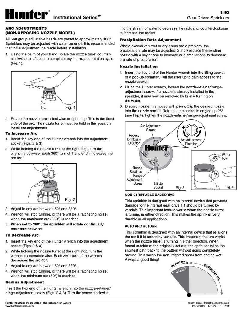
Hunter Institutional I-40 Series User manual

Hunter
Hunter ST Series User manual

Hunter
Hunter ST Series User manual

Hunter
Hunter X-CORE Operating instructions

Hunter
Hunter Professional Series PGP User manual

Hunter
Hunter SRC Plus 600i User manual
Hunter
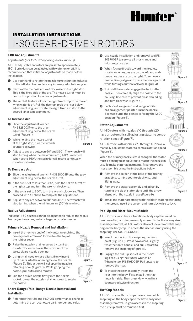
Hunter I-80 User manual

Hunter
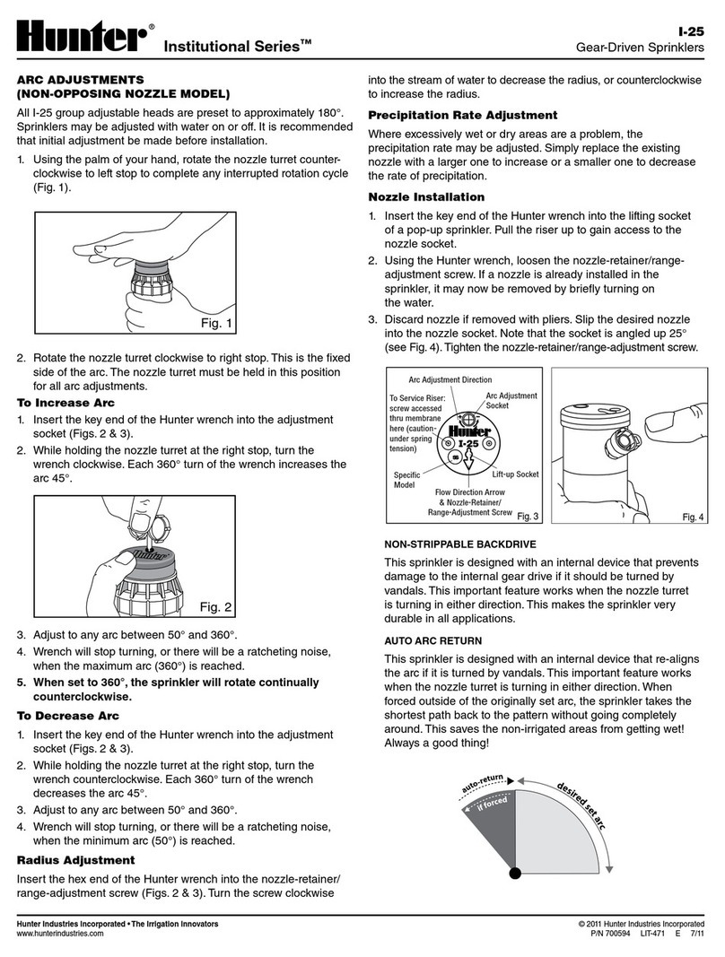
Hunter Institutional Series I-25 Plus User manual
Hunter
Hunter I-25 User manual

Hunter
Hunter PRO-C Hydrawise User manual

Hunter
Hunter Hydrawire User manual

Hunter
Hunter Institutional Series User manual
Popular Irrigation System manuals by other brands

Cellfast
Cellfast 52-305 user manual

Tyco Fire Product
Tyco Fire Product Star Galaxy SGQR instruction manual

Tyco Fire Product
Tyco Fire Product CENTRAL A instruction manual

Oral Care Technologies
Oral Care Technologies Hydro Floss Instructions for use

Reliable
Reliable F1-300 quick start guide

Tyco Fire Product
Tyco Fire Product Gem F892 instruction manual
