manuals.online logo
Brands
  1. Home
  2. •
  3. Brands
  4. •
  5. Hunter
  6. •
  7. Irrigation System
  8. •
  9. Hunter Institutional Series User manual

Hunter Institutional Series User manual

This manual suits for next models

2

Other Hunter Irrigation System manuals

Hunter Professional PGP Ultra Series User manual

Hunter

Hunter Professional PGP Ultra Series User manual

Hunter Institutional I-20 User manual

Hunter

Hunter Institutional I-20 User manual

Hunter Professional Series User manual

Hunter

Hunter Professional Series User manual

Hunter Institutional I-40 Series User manual

Hunter

Hunter Institutional I-40 Series User manual

Hunter Institutional Series User manual

Hunter

Hunter Institutional Series User manual

Hunter X-CORE Operating instructions

Hunter

Hunter X-CORE Operating instructions

Hunter Institutional Series I-35 User manual

Hunter

Hunter Institutional Series I-35 User manual

Hunter Professional Series PGP User manual

Hunter

Hunter Professional Series PGP User manual

Hunter I-20 ULTRA User manual

Hunter

Hunter I-20 ULTRA User manual

Hunter Professional Series User manual

Hunter

Hunter Professional Series User manual

Hunter Hydrawise Ready User manual

Hunter

Hunter Hydrawise Ready User manual

Hunter PRO-C Hydrawise User manual

Hunter

Hunter PRO-C Hydrawise User manual

Hunter Institutional Series User manual

Hunter

Hunter Institutional Series User manual

Hunter Institutional Series I-90 User manual

Hunter

Hunter Institutional Series I-90 User manual

Hunter PGP Ultra Series User manual

Hunter

Hunter PGP Ultra Series User manual

Hunter I-31 Plus User manual

Hunter

Hunter I-31 Plus User manual

Hunter PGP Series User manual

Hunter

Hunter PGP Series User manual

Hunter Institutional I-40 User manual

Hunter

Hunter Institutional I-40 User manual

Hunter I-60 Series User manual

Hunter

Hunter I-60 Series User manual

Hunter SRC Plus 600i User manual

Hunter

Hunter SRC Plus 600i User manual

Hunter Sprinkler System Guide

Hunter

Hunter Sprinkler System Guide

Hunter ST Series User manual

Hunter

Hunter ST Series User manual

Hunter ST Series User manual

Hunter

Hunter ST Series User manual

Hunter I-80 User manual

Hunter

Hunter I-80 User manual

Popular Irrigation System manuals by other brands

Tyco TY-B Series manual

Tyco

Tyco TY-B Series manual

Toro ZSERIES 570Z brochure

Toro

Toro ZSERIES 570Z brochure

OpenSprinkler OSPi user manual

OpenSprinkler

OpenSprinkler OSPi user manual

EINHELL GE-WW 5537 E Original operating instructions

EINHELL

EINHELL GE-WW 5537 E Original operating instructions

Cellfast 52-305 user manual

Cellfast

Cellfast 52-305 user manual

Tyco Fire Product Star Galaxy SGQR instruction manual

Tyco Fire Product

Tyco Fire Product Star Galaxy SGQR instruction manual

Tyco Fire Product CENTRAL A instruction manual

Tyco Fire Product

Tyco Fire Product CENTRAL A instruction manual

Oral Care Technologies Hydro Floss Instructions for use

Oral Care Technologies

Oral Care Technologies Hydro Floss Instructions for use

Reliable F1-300 quick start guide

Reliable

Reliable F1-300 quick start guide

Tyco Fire Product Gem F892 instruction manual

Tyco Fire Product

Tyco Fire Product Gem F892 instruction manual

Irrigation-Mart KIT-GK100-RV-B quick start guide

Irrigation-Mart

Irrigation-Mart KIT-GK100-RV-B quick start guide

Tyco CC3 manual

Tyco

Tyco CC3 manual

Reliable F4FR quick start guide

Reliable

Reliable F4FR quick start guide

Valley Bender160 owner's manual

Valley

Valley Bender160 owner's manual

Reliable F1FR42 Series manual

Reliable

Reliable F1FR42 Series manual

Toro 730 Series Installation and service instructions

Toro

Toro 730 Series Installation and service instructions

Eden 97063-EDAMZ quick start guide

Eden

Eden 97063-EDAMZ quick start guide

Netafim NETBEAT user manual

Netafim

Netafim NETBEAT user manual

manuals.online logo
manuals.online logoBrands
  • About & Mission
  • Contact us
  • Privacy Policy
  • Terms and Conditions

Copyright 2025 Manuals.Online. All Rights Reserved.

ARC ADJUSTMENT
The I-20 Ultra pop-up sprinkler should be installed at
nished grade as shown in the illustration (Fig. 1).
Arc Adjustments:
Adjustable heads are preset to approximately 180°.
Sprinklers may be adjusted with water on or off. It
is recommended that initial adjustments be made
before installation.
1. Using the palm of your hand, rotate the nozzle
turret counterclockwise to the left stop to complete
any interrupted rotation cycle (Fig. 2).
2. Rotate the nozzle turret clockwise to the right stop.
This is the xed side of the arc. The nozzle turret
must be held in this position for arc adjustments.
The right stop does not change.
To Increase the Arc:
1. Insert the plastic key end of the Hunter wrench into the
adjustment socket (Fig. 3 & 4).
2. While holding the nozzle turret at the right stop, turn the
wrench clockwise. Each full 360° turn of the wrench will
increase the arc 90°.
3. Adjust to any arc between 40° and 360° (Fig. 5).
4. The wrench will stop turning, or there will be a ratcheting
noise, when the maximum arc of 360° (full-circle) has been reached.
To Decrease the Arc:
1. Insert the plastic key end of the Hunter wrench into the adjustment socket (Fig. 3 & 4).
2. While holding the nozzle turret at the right stop, turn the wrench counterclockwise.
Each full 360° turn of the wrench will decrease the arc 90°.
3. Adjust to any arc between 40° and 360° (Fig. 5).
4. The wrench will stop turning, or there will be a ratcheting noise, when the minimum arc of 40°
has been reached.
Note: It is not necessary to disassemble the sprinkler to make adjustments.
'JH
'JH
'JH
'JH
'JH
'JH
A
R
C
ADS
O
F
F
I-20
-JGUJOH
4PDLFU
/P[[MF
-PDBUPS3BEJVT
"EKVTUNFOU
4DSFX
.PEFM
*EFOUJGJDBUJPO
.JOJNVN
"SD
1MBTUJD,FZ&OE
4UFFM)FY&OE

o

o
.BYJNVN
"SD
"SD
"EKVTUNFOU
'MP4UPQ¡
%FDSFBTF"SD*ODSFBTF"SD
RADIUS / DISTANCE OF THROW
Insert the steel hex end of the Hunter wrench into the radius
adjustment screw (Fig. 6). Turn the screw clockwise (into the stream
of water) to decrease the radius, or counterclockwise to increase the
radius. Radius can be reduced up to 25%.
PRECIPITATION RATE ADJUSTMENT
If you have excessively wet or dry
areas, you can change the nozzle
in the sprinkler to increase or decrease
the precipitation rate. For dry areas,
install a larger nozzle. For wet areas,
install a smaller nozzle.
'JH
'JH
'JH
'JH
'JH
'JH
A
R
C
ADS
O
F
F
I-20
-JGUJOH
4PDLFU
/P[[MF
-PDBUPS3BEJVT
"EKVTUNFOU
4DSFX
.PEFM
*EFOUJGJDBUJPO
.JOJNVN
"SD
1MBTUJD,FZ&OE
4UFFM)FY&OE

o

o
.BYJNVN
"SD
"SD
"EKVTUNFOU
'MP4UPQ¡
%FDSFBTF"SD*ODSFBTF"SD
'JH
'JH
'JH
'JH
'JH
'JH
A
R
C
ADS
O
F
F
I-20
-JGUJOH
4PDLFU
/P[[MF
-PDBUPS3BEJVT
"EKVTUNFOU
4DSFX
.PEFM
*EFOUJGJDBUJPO
.JOJNVN
"SD
1MBTUJD,FZ&OE
4UFFM)FY&OE

o

o
.BYJNVN
"SD
"SD
"EKVTUNFOU
'MP4UPQ¡
%FDSFBTF"SD*ODSFBTF"SD
'JH
'JH
'JH
'JH
'JH
'JH
A
R
C
ADS
O
F
F
I-20
-JGUJOH
4PDLFU
/P[[MF
-PDBUPS3BEJVT
"EKVTUNFOU
4DSFX
.PEFM
*EFOUJGJDBUJPO
.JOJNVN
"SD
1MBTUJD,FZ&OE
4UFFM)FY&OE

o

o
.BYJNVN
"SD
"SD
"EKVTUNFOU
'MP4UPQ¡
%FDSFBTF"SD*ODSFBTF"SD
'JH
'JH
'JH
'JH
'JH
'JH
A
R
C
ADS
O
F
F
I-20
-JGUJOH
4PDLFU
/P[[MF
-PDBUPS3BEJVT
"EKVTUNFOU
4DSFX
.PEFM
*EFOUJGJDBUJPO
.JOJNVN
"SD
1MBTUJD,FZ&OE
4UFFM)FY&OE

o

o
.BYJNVN
"SD
"SD
"EKVTUNFOU
'MP4UPQ
¡
%FDSFBTF"SD*ODSFBTF"SD
'JH
'JH
'JH
'JH
'JH
'JH
A
R
C
ADS
O
F
F
I-20
-JGUJOH
4PDLFU
/P[[MF
-PDBUPS3BEJVT
"EKVTUNFOU
4DSFX
.PEFM
*EFOUJGJDBUJPO
.JOJNVN
"SD
1MBTUJD,FZ&OE
4UFFM)FY&OE

o

o
.BYJNVN
"SD
"SD
"EKVTUNFOU
'MP4UPQ
¡
%FDSFBTF"SD*ODSFBTF"SD
NOZZLE INSTALLATION
1. Insert the plastic key end of the Hunter wrench into the
lifting socket of the sprinkler and turn 90°. Pull the riser up
to gain access to the nozzle socket (Fig. 8).
2. Using the hex key of the Hunter wrench, turn the radius
adjustment screw (Fig. 6) counterclockwise to be sure it
is not blocking the nozzle socket opening. If a nozzle is
already installed, it can be removed by backing out the
adjustment screw and turning on the water, or by pulling
outward on the nozzle removal post with a pair of needle-
nosed pliers.
3. Slip the desired nozzle into the nozzle socket (Fig. 7). Note
that the socket is angled up 25°. Then tighten the nozzle
range screw. The triangle on the rubber cover will always
indicate the location of the nozzle and direction of water
ow when the sprinkler is retracted.
'JH
'JH
'JH
'JH
/P[[MF3FNPWBM
1PTU
Caution: Turning the adjustment screw
clockwise more than ve full turns may
result in a lost radius adjustment screw.
Hunter Industries Incorporated • The Irrigation Innovators © 2007 Hunter Industries Incorporated
www.HunterIndustries.com P/N 700053 LIT-053 4/07
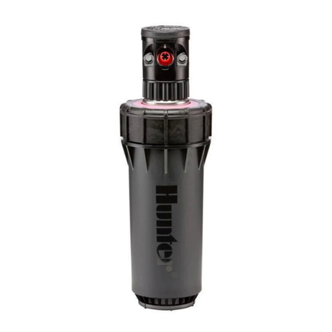
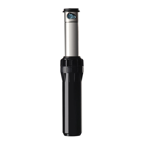
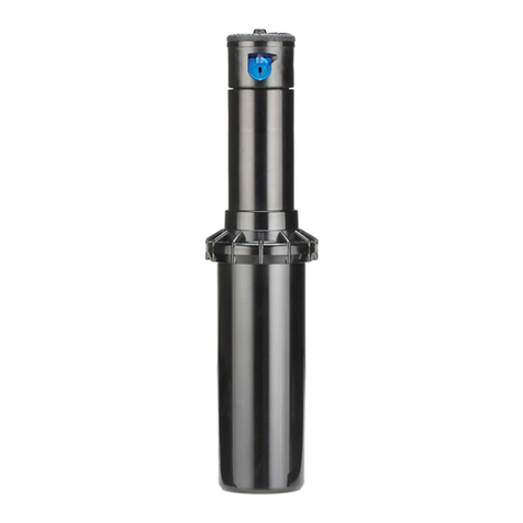
Institutional Series™
I-10 & I-20 Ultra
Gear-Driven Sprinklers Institutional Series™
I-10 & I-20 Ultra
Gear-Driven Sprinklers
Institutional Series™
I-10 & I-20 Ultra
Gear-Driven Sprinklers
I-10/I-20 Ultra Low Angle Nozzle
Performance Data
Pressure Radius Flow Precip in/hr
Nozzle PSI ft. GPM
2.0
LA
30
40
50
60
25'
27'
28'
30'
1.6
1.9
2.1
2.3
0.49
0.50
0.52
0.49
0.57
0.58
0.60
0.57
2.5
LA
30
40
50
60
27'
30'
33'
35'
2.1
2.5
2.8
3.0
0.55
0.53
0.49
0.47
0.64
0.62
0.57
0.54
3.5
LA
30
40
50
60
29'
32'
35'
37'
2.8
3.1
3.5
3.8
0.64
0.58
0.55
0.53
0.74
0.67
0.64
0.62
4.5
LA
30
40
50
60
29'
32'
35'
37'
3.4
3.9
4.4
4.7
0.78
0.73
0.69
0.66
0.90
0.85
0.80
0.76
Note: All precipitation rates are calculated for 180 degree operation.
For the precipitation rate for a 360 degree sprinkler, divide by 2.
I-10/I-20 Ultra Low Angle Nozzle
Performance Data – Metric
Pressure Radius Flow Precip mm/hr
Nozzle Bars kPa m m3/hr l/min
2.0
LA
1.7
2.0
2.5
3.0
3.5
4.0
4.5
172
200
248
303
352
400
448
7.3
7.6
7.9
8.2
8.5
8.8
9.1
0.33
0.36
0.40
0.45
0.48
0.52
0.55
5.6
6.0
6.7
7.4
8.0
8.6
9.1
12
12
13
13
13
13
13
14
14
15
15
15
15
15
2.5
LA
1.7
2.0
2.5
3.0
3.5
4.0
4.5
172
200
248
303
352
400
448
7.9
8.2
8.8
9.4
10.1
10.4
10.7
0.44
0.47
0.53
0.59
0.64
0.68
0.72
7.3
7.9
8.8
9.8
10.6
11.3
12.0
14
14
14
13
13
13
13
16
16
16
15
15
15
15
3.5
LA
1.7
2.0
2.5
3.0
3.5
4.0
4.5
172
200
248
303
352
400
448
8.5
8.8
9.1
10.1
10.7
11.0
11.3
0.58
0.62
0.68
0.75
0.80
0.85
0.89
9.7
10.3
11.4
12.5
13.3
14.1
14.8
16
16
16
15
14
14
14
18
18
19
17
16
16
16
4.5
LA
1.7
2.0
2.5
3.0
3.5
4.0
4.5
172
200
248
303
352
400
448
8.2
8.8
9.1
10.1
10.7
11.0
11.3
0.71
0.76
0.84
0.93
1.00
1.06
1.12
11.8
12.7
14.1
15.5
16.6
17.6
18.6
21
19
20
18
18
18
18
24
23
23
21
20
20
20
Note: All precipitation rates are calculated for 180 degree operation.
For the precipitation rate for a 360 degree sprinkler, divide by 2.
I-10/I-20 Ultra Standard Nozzle
Performance Data
Pressure Radius Flow Precip in/hr
Nozzle PSI ft. GPM
1.0
30
40
50
60
30'
31'
31'
32'
0.9
1.0
1.2
1.3
0.19
0.20
0.24
0.24
0.22
0.23
0.28
0.28
1.5
30
40
50
60
32'
33'
34'
34'
1.2
1.4
1.6
1.8
0.23
0.25
0.27
0.30
0.26
0.29
0.31
0.35
2.0
30
40
50
60
32'
34'
36'
36'
1.6
1.8
2.0
2.2
0.30
0.30
0.30
0.33
0.35
0.35
0.34
0.38
3.0
30
40
50
60
34'
36'
38'
38'
2.0
2.4
2.7
2.9
0.33
0.36
0.36
0.39
0.38
0.41
0.42
0.45
3.5
30
40
50
60
34'
38'
40'
40'
2.6
3.0
3.4
3.7
0.43
0.40
0.41
0.45
0.52
0.46
0.47
0.51
4.0
30
40
50
60
37'
39'
41'
42'
3.2
3.7
4.2
4.6
0.45
0.47
0.48
0.50
0.52
0.54
0.56
0.58
6.0
30
40
50
60
35'
40'
43'
44'
4.2
4.9
5.5
6.0
0.66
0.59
0.57
0.60
0.76
0.68
0.66
0.69
8.0
40
50
60
70
41'
44'
45'
47'
6.0
6.8
7.6
8.2
0.69
0.68
0.72
0.71
0.79
0.78
0.83
0.83
I-10/I-20 Ultra Standard Nozzle
Performance Data – Metric
Pressure Radius Flow Precip mm/hr
Nozzle Bars kPa m m3/hr l/min
1.0
1.7
2.0
2.5
3.0
3.5
4.0
4.5
172
200
248
303
352
400
448
8.8
9.1
9.4
9.4
9.4
9.8
9.8
0.18
0.20
0.22
0.25
0.27
0.29
0.31
3.0
3.3
3.7
4.1
4.5
4.8
5.1
5
5
5
6
6
6
6
5
5
6
6
7
7
7
1.5
1.7
2.0
2.5
3.0
3.5
4.0
4.5
172
200
248
303
352
400
448
9.4
9.8
9.8
10.1
10.4
10.4
10.4
0.24
0.27
0.30
0.34
0.37
0.40
0.43
4.1
4.4
5.0
5.6
6.2
6.6
7.1
5
6
6
7
7
7
8
6
6
7
8
8
9
9
2.0
1.7
2.0
2.5
3.0
3.5
4.0
4.5
172
200
248
303
352
400
448
9.4
9.8
9.8
10.4
11.0
11.0
11.0
0.33
0.36
0.39
0.43
0.46
0.49
0.51
5.5
5.9
6.5
7.2
7.7
8.1
8.6
7
7
8
8
8
8
9
9
9
10
9
9
9
10
3.0
1.7
2.0
2.5
3.0
3.5
4.0
4.5
172
200
248
303
352
400
448
10.1
10.4
10.4
11.0
11.6
11.6
11.6
0.42
0.45
0.51
0.57
0.61
0.66
0.70
6.9
7.5
8.5
9.4
10.2
10.9
11.6
8
8
9
9
9
10
10
10
10
11
11
11
11
12
3.5
1.7
2.0
2.5
3.0
3.5
4.0
4.5
172
200
248
303
352
400
448
10.1
10.4
11.0
11.3
11.6
11.6
11.6
0.54
0.58
0.65
0.72
0.78
0.83
0.88
9.0
9.7
10.8
12.0
12.9
13.8
14.6
11
11
11
11
12
12
13
12
12
12
13
13
14
15
4.0
1.7
2.0
2.5
3.0
3.5
4.0
4.5
172
200
248
303
352
400
448
11.0
11.3
11.6
11.9
12.5
12.5
12.8
0.66
0.71
0.80
0.89
0.96
1.03
1.09
11.0
11.9
13.3
14.8
16.0
17.1
18.2
11
11
12
13
12
13
13
13
13
14
15
14
15
15
6.0
1.7
2.0
2.5
3.0
3.5
4.0
4.5
172
200
248
303
352
400
448
9.8
10.7
11.3
11.9
13.1
13.1
13.4
0.87
0.94
1.05
1.17
1.26
1.34
1.43
14.5
15.7
17.5
19.4
21.0
22.4
23.8
18
17
17
16
15
16
16
21
19
19
19
17
18
18
8.0
1.7
2.0
2.5
3.0
3.5
4.0
4.5
172
200
248
303
352
400
448
11.3
11.9
12.5
13.1
13.4
13.7
14.3
1.05
1.14
1.29
1.44
1.56
1.68
1.79
17.4
19.0
21.4
24.0
26.1
28.0
29.9
16
16
16
17
17
18
17
19
19
19
19
20
21
20
Note: All precipitation rates are calculated for 180 degree operation.
For the precipitation rate for a 360 degree sprinkler, divide by 2.
'JH
'JH
'JH
'JH
/P[[MF3FNPWBM
1PTU
ALIGNING THE RIGHT (FIXED) SIDE OF ARC
If the right side of the arc is not properly aligned, the results may
be a wet walkway or a dry turf area. The right side arc can easily
be realigned. One way to realign the right stop is to turn the whole
sprinkler body assembly and the tting below it, left or right to the
desired position. This may require temporary removal of the soil
around the sprinkler to allow you to grip the sprinkler housing.
Another way to reset the right arc is to unscrew the body cap
counterclockwise and remove the internal assembly from the body.
Once removed, rotate the nozzle turret to the right stop, screw the
TURNING FLOW ON OR OFF
Insert the plastic key end of the Hunter wrench into the FloStop® adjustment socket (Fig. 3 & 10).
Turn wrench clockwise to decrease or shut off the ow. Turn the wrench counterclockwise to
increase the ow.
internal assembly back into the body with
the nozzle aligned to the right side of the
area you want irrigated (Fig. 9). At this
point you have realigned the right arc
stop, and you can adjust the left arc to an
appropriate setting.
Note: It is not necessary to dig up and
remove the whole sprinkler to realign the
right arc.
Institutional Series™
I-10 & I-20 Ultra
Gear-Driven Sprinklers
Institutional Series™
I-10 & I-20 Ultra
Gear-Driven Sprinklers
I-10/I-20 Ultra Low Angle Nozzle
Performance Data
Pressure Radius Flow Precip in/hr
Nozzle PSI ft. GPM
2.0
LA
30
40
50
60
25'
27'
28'
30'
1.6
1.9
2.1
2.3
0.49
0.50
0.52
0.49
0.57
0.58
0.60
0.57
2.5
LA
30
40
50
60
27'
30'
33'
35'
2.1
2.5
2.8
3.0
0.55
0.53
0.49
0.47
0.64
0.62
0.57
0.54
3.5
LA
30
40
50
60
29'
32'
35'
37'
2.8
3.1
3.5
3.8
0.64
0.58
0.55
0.53
0.74
0.67
0.64
0.62
4.5
LA
30
40
50
60
29'
32'
35'
37'
3.4
3.9
4.4
4.7
0.78
0.73
0.69
0.66
0.90
0.85
0.80
0.76
Note: All precipitation rates are calculated for 180 degree operation.
For the precipitation rate for a 360 degree sprinkler, divide by 2.
I-10/I-20 Ultra Low Angle Nozzle
Performance Data – Metric
Pressure Radius Flow Precip mm/hr
Nozzle Bars kPa m m3/hr l/min
2.0
LA
1.7
2.0
2.5
3.0
3.5
4.0
4.5
172
200
248
303
352
400
448
7.3
7.6
7.9
8.2
8.5
8.8
9.1
0.33
0.36
0.40
0.45
0.48
0.52
0.55
5.6
6.0
6.7
7.4
8.0
8.6
9.1
12
12
13
13
13
13
13
14
14
15
15
15
15
15
2.5
LA
1.7
2.0
2.5
3.0
3.5
4.0
4.5
172
200
248
303
352
400
448
7.9
8.2
8.8
9.4
10.1
10.4
10.7
0.44
0.47
0.53
0.59
0.64
0.68
0.72
7.3
7.9
8.8
9.8
10.6
11.3
12.0
14
14
14
13
13
13
13
16
16
16
15
15
15
15
3.5
LA
1.7
2.0
2.5
3.0
3.5
4.0
4.5
172
200
248
303
352
400
448
8.5
8.8
9.1
10.1
10.7
11.0
11.3
0.58
0.62
0.68
0.75
0.80
0.85
0.89
9.7
10.3
11.4
12.5
13.3
14.1
14.8
16
16
16
15
14
14
14
18
18
19
17
16
16
16
4.5
LA
1.7
2.0
2.5
3.0
3.5
4.0
4.5
172
200
248
303
352
400
448
8.2
8.8
9.1
10.1
10.7
11.0
11.3
0.71
0.76
0.84
0.93
1.00
1.06
1.12
11.8
12.7
14.1
15.5
16.6
17.6
18.6
21
19
20
18
18
18
18
24
23
23
21
20
20
20
Note: All precipitation rates are calculated for 180 degree operation.
For the precipitation rate for a 360 degree sprinkler, divide by 2.
I-10/I-20 Ultra Standard Nozzle
Performance Data
Pressure Radius Flow Precip in/hr
Nozzle PSI ft. GPM
1.0
30
40
50
60
30'
31'
31'
32'
0.9
1.0
1.2
1.3
0.19
0.20
0.24
0.24
0.22
0.23
0.28
0.28
1.5
30
40
50
60
32'
33'
34'
34'
1.2
1.4
1.6
1.8
0.23
0.25
0.27
0.30
0.26
0.29
0.31
0.35
2.0
30
40
50
60
32'
34'
36'
36'
1.6
1.8
2.0
2.2
0.30
0.30
0.30
0.33
0.35
0.35
0.34
0.38
3.0
30
40
50
60
34'
36'
38'
38'
2.0
2.4
2.7
2.9
0.33
0.36
0.36
0.39
0.38
0.41
0.42
0.45
3.5
30
40
50
60
34'
38'
40'
40'
2.6
3.0
3.4
3.7
0.43
0.40
0.41
0.45
0.52
0.46
0.47
0.51
4.0
30
40
50
60
37'
39'
41'
42'
3.2
3.7
4.2
4.6
0.45
0.47
0.48
0.50
0.52
0.54
0.56
0.58
6.0
30
40
50
60
35'
40'
43'
44'
4.2
4.9
5.5
6.0
0.66
0.59
0.57
0.60
0.76
0.68
0.66
0.69
8.0
40
50
60
70
41'
44'
45'
47'
6.0
6.8
7.6
8.2
0.69
0.68
0.72
0.71
0.79
0.78
0.83
0.83
I-10/I-20 Ultra Standard Nozzle
Performance Data – Metric
Pressure Radius Flow Precip mm/hr
Nozzle Bars kPa m m3/hr l/min
1.0
1.7
2.0
2.5
3.0
3.5
4.0
4.5
172
200
248
303
352
400
448
8.8
9.1
9.4
9.4
9.4
9.8
9.8
0.18
0.20
0.22
0.25
0.27
0.29
0.31
3.0
3.3
3.7
4.1
4.5
4.8
5.1
5
5
5
6
6
6
6
5
5
6
6
7
7
7
1.5
1.7
2.0
2.5
3.0
3.5
4.0
4.5
172
200
248
303
352
400
448
9.4
9.8
9.8
10.1
10.4
10.4
10.4
0.24
0.27
0.30
0.34
0.37
0.40
0.43
4.1
4.4
5.0
5.6
6.2
6.6
7.1
5
6
6
7
7
7
8
6
6
7
8
8
9
9
2.0
1.7
2.0
2.5
3.0
3.5
4.0
4.5
172
200
248
303
352
400
448
9.4
9.8
9.8
10.4
11.0
11.0
11.0
0.33
0.36
0.39
0.43
0.46
0.49
0.51
5.5
5.9
6.5
7.2
7.7
8.1
8.6
7
7
8
8
8
8
9
9
9
10
9
9
9
10
3.0
1.7
2.0
2.5
3.0
3.5
4.0
4.5
172
200
248
303
352
400
448
10.1
10.4
10.4
11.0
11.6
11.6
11.6
0.42
0.45
0.51
0.57
0.61
0.66
0.70
6.9
7.5
8.5
9.4
10.2
10.9
11.6
8
8
9
9
9
10
10
10
10
11
11
11
11
12
3.5
1.7
2.0
2.5
3.0
3.5
4.0
4.5
172
200
248
303
352
400
448
10.1
10.4
11.0
11.3
11.6
11.6
11.6
0.54
0.58
0.65
0.72
0.78
0.83
0.88
9.0
9.7
10.8
12.0
12.9
13.8
14.6
11
11
11
11
12
12
13
12
12
12
13
13
14
15
4.0
1.7
2.0
2.5
3.0
3.5
4.0
4.5
172
200
248
303
352
400
448
11.0
11.3
11.6
11.9
12.5
12.5
12.8
0.66
0.71
0.80
0.89
0.96
1.03
1.09
11.0
11.9
13.3
14.8
16.0
17.1
18.2
11
11
12
13
12
13
13
13
13
14
15
14
15
15
6.0
1.7
2.0
2.5
3.0
3.5
4.0
4.5
172
200
248
303
352
400
448
9.8
10.7
11.3
11.9
13.1
13.1
13.4
0.87
0.94
1.05
1.17
1.26
1.34
1.43
14.5
15.7
17.5
19.4
21.0
22.4
23.8
18
17
17
16
15
16
16
21
19
19
19
17
18
18
8.0
1.7
2.0
2.5
3.0
3.5
4.0
4.5
172
200
248
303
352
400
448
11.3
11.9
12.5
13.1
13.4
13.7
14.3
1.05
1.14
1.29
1.44
1.56
1.68
1.79
17.4
19.0
21.4
24.0
26.1
28.0
29.9
16
16
16
17
17
18
17
19
19
19
19
20
21
20
Note: All precipitation rates are calculated for 180 degree operation.
For the precipitation rate for a 360 degree sprinkler, divide by 2.
'JH
'JH
'JH
'JH
/P[[MF3FNPWBM
1PTU
ALIGNING THE RIGHT (FIXED) SIDE OF ARC
If the right side of the arc is not properly aligned, the results may
be a wet walkway or a dry turf area. The right side arc can easily
be realigned. One way to realign the right stop is to turn the whole
sprinkler body assembly and the tting below it, left or right to the
desired position. This may require temporary removal of the soil
around the sprinkler to allow you to grip the sprinkler housing.
Another way to reset the right arc is to unscrew the body cap
counterclockwise and remove the internal assembly from the body.
Once removed, rotate the nozzle turret to the right stop, screw the
TURNING FLOW ON OR OFF
Insert the plastic key end of the Hunter wrench into the FloStop® adjustment socket (Fig. 3 & 10).
Turn wrench clockwise to decrease or shut off the ow. Turn the wrench counterclockwise to
increase the ow.
internal assembly back into the body with
the nozzle aligned to the right side of the
area you want irrigated (Fig. 9). At this
point you have realigned the right arc
stop, and you can adjust the left arc to an
appropriate setting.
Note: It is not necessary to dig up and
remove the whole sprinkler to realign the
right arc.
Institutional Series™
I-10 & I-20 Ultra
Gear-Driven Sprinklers