Hunter EZ-DM User manual

ENGLISH
The EZ Decoder System is a unique two-wire output option for
Hunter ICC2 and HCC controller models only.
• Do not attempt to use this system with any other model or
brand of controller.
• Do not attempt to use EZ-1 decoders with any other decoder
controller.
EZ Decoders are designed to be easy.
They do not require special wire.
• They do require direct burial wire of adequate size for the
distance of each wire run (see chart). It is even possible to use
existing wire from “conventional” installations to create a two-
wire path for EZ decoders.
• The EZ Decoder System does not require waterproof
connections in order to operate. However, just as in
conventional systems, waterproof connectors should be used to
maintain the integrity of the splice and the wire.
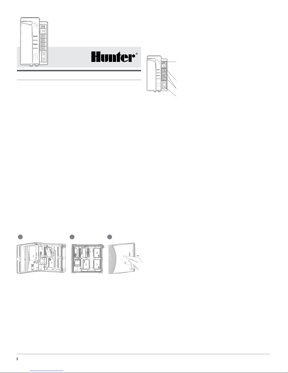
Installing the EZ-DM in Hunter ICC2 and HCC Controllers
If the whole system will be two-wire, install the EZ-DM module in
the rst slot in the controller.
Press the Reset button on the back of the controller face panel for
the new module to be recognized.
• Open blue lock lever.
• Insert module tabs into end of slot, and tip into place.
• Close locking lever.
• Press controller Reset button. Controller will then recognize the
new module, and the controller
size will change to 54 stations.
EZ-DM may also be combined with ICM-800 and ICM-400
modules for “hybrid” operation. They can use “conventional”
solenoid wiring and two-wire technology at the same time, up to
54 stations maximum.
It is recommended to install all conventional modules in the lower-
numbered slots, and install the EZ-DM in the next available slot.
• The conventional modules will operate the station numbers that
are shown on the backplane of the controller, next to the slot.
• The EZ-DM module can operate remaining station numbers up
to 54 via the two-wire paths.
• Do not program duplicate station numbers when combining
conventional modules and the EZ-DM. If an EZ decoder is
programmed to station 1, and there is a conventional module in
the rst output slot with station 1, both station “ones” will turn
on at the same time. This may cause a station error if it causes
an overloaded current condition.
• Only program decoder station numbers that are not in use on
conventional output modules.
EZ-DM Connections
P/MV (Pump/Master Valve): Connects to
P/MV on power module ONLY if decoder will
be used for P/MV
Program button and status LED
Two-Wire path terminals (two paths available)
Decoder Programming Port: Insert decoder red
and blue wires for programming.
Decoder Programming
• Each EZ-1 Decoder must be programmed with a station number
(or as the P/MV) before use.
• Insert EZ-1 red and blue wires into ports on the EZ-DM output
module. It does not matter which color goes in which hole. Use
the controller face panel (or remote control, if so equipped) to
start the station number you want to program into the decoder.
• When the station is shown running in the controller display,
press the PRG button on the EZDM. When the LED illuminates
on the decoder, the decoder is programmed with that station’s
number. Write the station number on the decoder label with a
permanent marker. It is now ready to install in the two-wire path
at a valve location.
P/MV (Pump/Master Valve)
To program P/MV output for decoder: With no stations running,
connect the decoder to the port, and press the PRG button on
the EZDM. When the decoder LED illuminates, the decoder is
programmed as the P/MV output.
IMPORTANT: Connect a jumper wire from the P/MV terminal
on the controller power module, to the P/MV terminal on the
decoder output module, for decoder operation of P/MV. If the P/
MV output will not be used, or if the P/MV is nearby and will be
wired directly to the controller without a decoder, do not install a
jumper wire. The P/MV output on the controller power module
will operate normally if the jumper wire is not connected.
Two-Wire Path Connections and Rules
• The output of the EZ-DM wire paths is 24VAC, 50/60 Hz.
Voltage is only present on the paths when stations are active.
• The red and blue wire path terminals on the EZ-DM indicate that
they are connected to the EZ-1 decoder red and blue wires, but
the wire that extends the two-wire path does not need to be
color-coded. It does not matter if the decoder “red” connects to
the terminal “blue.”
• There is no polarity on the EZ decoder system. Use direct
burial-rated irrigation wire.
• The size of the wire determines the eective distance of the
two-wire path.
• See the wiring table for distance specications with various wire
sizes.
• Use irrigation-grade wire connectors for all splices. They can be
of the same type used for solenoid connections.
Learn more. Visit hunterindustries.com
EZ-DM
Decoder Output Module
Installation Guide for ICC2
and HCC Controllers
RESET
21 3

NOTE: Distances in the Wiring Table are calculated based on 60 Hz
for American Wire Gauge, and 50 Hz for International, with wire
temperature of 122°F (50°C), and a 10% safety factor.
Converting Existing Wiring
It is possible to convert an existing conventionally wired system to
EZ decoder operation by using existing wire bundles to create a
two-wire path to each valve location and adding an EZ-1 decoder
at each valve.
Tee-Splicing the Two-Wire Paths
Tee-splicing the two-wire path is permissible. Use waterproof
connectors in a valve box, and adequate slack at the splices (5
/1.5 m) to insure a reliable connection. Size the wire for the most
distant decoder from the controller.
Earth Grounding
Earth grounding is not required in the two-wire path. However,
it may be added in high-lightning areas for additional protection.
Use Hunter model DUAL-S surge arrestors and connect the surge
arrestor ground wire to earth ground hardware. Earth grounding
hardware should consist of a 8’ (2.5 m) copper-clad steel rod, or a
copper plate, installed at least 8' (2.5 m) away from the
two-wire path.
The ICC2 or HCC controller should be grounded to earth with the
ground attachment on side of the transformer cover, to approved
earth ground hardware, ideally to a resistance of 10 ohms or less,
as shown in the controller installation instructions.
Operation
EZ Decoders do not require special operating procedures, and the
programmed decoders will operate exactly like conventionally-
wired stations. When a decoder station begins to operate, the
EZ-DM light will blink rapidly while rst communicating, then blink
at approximately one-second intervals during the station run time.
When the EZ-1 decoder is actively running, the decoder LED will
also blink at approximately one-second intervals. If the decoder
light does not blink when the controller display indicates the
station is running, the decoder may be either disconnected
or damaged.
NOTE: The Hunter ICC2 QuickCheckTM feature cannot work with
EZ Decoders! The function will still work with any conventional
stations in a hybrid system, but is not intended for use with
EZ Decoders.
Troubleshooting
Compliance Information
FCC Notice
This equipment generates, uses, and can radiate radio frequency
energy and, if not installed and used in accordance with the
manufacturer’s instruction manual, may cause interference with
radio and television reception. This equipment has been tested
and found to comply with the limits for a Class B digital device,
pursuant to part 15 of the FCC Rules. Operation is subject to the
following two conditions:
1) This device may not cause harmful interference.
2) This device must accept any interference received, including
interference that may cause undesired operation.
American Wire
Gauge
Distance Feet International
Wire mm
Distance
meters
18 AWG 908 0.8 mm267
16 AWG 1446 1 mm 333
14 AWG 2292 1.5 mm 500
12 AWG 3650 2.5 mm 833
4 mm 1333
Symptom Possible Causes Corrective Action
New Module
does not work;
station count
is incorrect
• Controller was
not reset aer
module installed.
• Press Reset button on the
back of the control panel.
Station will not
run
• Decoder not
programmed or
programmed
to the wrong
station
• Decoder
or solenoid
disconnected
• Bad solenoid
• Start manual station
activation, and verify station
is running in the display.
• Inspect decoder, verify the
LED is ashing at one-
second rate. If not,
check for 24VAC at decoder
connection to two-wire path.
• If light is ashing, decoder is
working, check solenoid and
connection to wire leads.
• If necessary, re-program
decoder to correct
station number.
P/MV will not
operate
• Decoder not
programmed as
PM/V
• Wire jumper not
installed
• Re-program decoder with NO
stations running.
• Install jumper wire between
EZ-DM PMV terminal, and
PMV terminal on controller
power module.
Err message in
display
Note: When
errors occur
on the two-
wire path,
the controller
cannot directly
identify which
station caused
a problem (like
it can with
conventional
stations and
PMV). Start
stations
manually to see
when the
Err occurs.
• Overload
condition in the
eld
• Possible short in
two-wire path
• Possible
duplicate station
numbers; too
many solenoids
active
• (Station number
shown in Err
display may not
be correct with
EZ-DM installed)
• The solenoid is damaged,
causing a high current draw;
check resistance.
• If error occurs on all stations,
check for dead short in two-
wire path or PM/V output.
• Eliminate decoder stations
with same number as
conventional stations in use.
QuickCheck
advances
through
all zones
without results
• QuickCheck not
intended for use
with EZ Decoders
• N/A
Learn more. Visit hunterindustries.com

Notice: The FCC regulations provide that changes or modications
not expressly approved by Hunter Industries could void your
authority to operate this equipment. These limits are designed
to provide reasonable protection against harmful interference
in a residential installation. However, there is no guarantee
that interference will not occur in a particular installation. If this
equipment does cause harmful interference to radio or television
reception, which can be determined by turning the equipment o
and on, the user is encouraged to try to correct the interference by
one or more of the following measures:
• Reorient or relocate the receiving antenna.
• Increase the separation between the equipment and receiver.
• Connect the equipment into an outlet on a circuit dierent from
that to which the receiver is connected.
• Consult the dealer or an experienced radio/TV
technician for help.
Industry Canada Notice
This device complies with Industry Canada license-exempt RSS
standard(s). Operation is subject to the following two conditions:
(1) this device may not cause interference, and
(2) this device must accept any interference, including
interference that may cause undesired operation of the device.
Le présent appareil est conforme aux CNR d’Industrie Canada
applicables aux appareils radio exempts de licence. L’exploitation
est autorisée aux deux conditions suivantes:
(1) l’appareil ne doit pas produire de brouillage, et
(2) l’utilisateur de l’appareil doit accepter tout brouillage
radioélectrique subi, même si le brouillage est susceptible d’en
compromettre le fonctionnement.
CE Notice
Hunter Industries hereby declares that this product is in
compliance with the essential requirements and other relevant
provisions of Directives 2014/35/EU (low voltage) and 2014/30/
EU (electromagnetic compatibility).
© 2019 Hunter Industries Inc. Hunter, the Hunter logo, and all other trademarks are property of Hunter Industries, registered in the U.S. and other countries.
RC-101-EZDM-US 2/19
Learn more. Visit hunterindustries.com
Table of contents
Other Hunter Media Converter manuals