Hunter ICD400 Series User manual

ICD400/600 Series Decoder
FCC Notice
FCC ID: M3UICDDEC
This device complies with FCC rules Part 15. Operation is subject to the following two conditions:
• This device may not cause harmful interference and
• This device must accept any interference received, including interference that may cause undesired operation.
This equipment has been tested and found to comply with the limits for class B digital devices, pursuant to part 15 of the
FCC Rules. These limits are designed to provide reasonable protection against harmful interference in a residential
installation.
This equipment generates, uses, and can radiate radio frequency energy and if not installed and used in accordance with
the instructions, may cause harmful interference to radio communications. However, there is no guarantee that
interference will not occur in a particular installation. If this equipment does cause harmful interference to radio or
television reception, which can be determined by turning the equipment on and off, the user is encouraged to try to
correct the interference by one or more of the following measures:
• Reorient or relocate the receiving antenna
• Increase the separation between the equipment and the receiver
• Connect the equipment to an outlet on a circuit different from that to which the receiver is connected
• Consult the dealer or an experienced radio/TV technician for help
The user is cautioned that changes and modification made to the equipment without the approval of the manufacturer
could void the user’s authority to operate this equipment.
Installation Instructions
This package includes:
(1) ICD400 or ICD600 decoder module
(1) Instruction Sheet
Tools/supplies required* (not included):
DBRY-6 high-voltage waterproof connectors or
equivalent
DBY waterproof connectors or equivalent
Wire strippers
Optional earth grounding hardware
The ICD Series decoders may be connected to the Hunter ACC, AGC, Genesis, VSX, and IDS decoder controllers.
•In the ACC or AGC controllers, each decoder is programmed with station address(es) at the controller,
before installing it in the 2-wire path. These controllers have a programming port on the decoder output module.
Program the station number(s) into the decoder, and then write the station number assignments on the metallic tag
on the decoder. The 8-digit serial number is not used in the decoder set-up on these controllers.
•ICD Decoders may also be programmed with the Hunter Industries Model ICD-HP handheld programmer,
after installation.
1. In the ACC/AGC series of controllers, first Insert the red and blue wires from the decoder into the Programming Ports on
the decoder output module (ADM99).
2. Use the procedure in the ACC / AGC owner’s manual for addressing decoders. Use a ballpoint pen to write the station
number(s) on the decoder’s metallic tag.
Each decoder output can power two standard 24VAC Hunter solenoids. They must be wired in parallel, as shown in step 9.
•In Genesis, VSX, and IDS controllers, the decoder can be installed on the 2-wire path before giving it a station
address using the 7-digit serial number followed by “x”. The 8-digit serial number is required for station addressing

Hunter Industries
1940 Diamond Street •San Marcos, California 92078 •TEL (1) 760-744-5240 •Field Services (800) 248-6561 •FAX (1) 760-591-9582 •
www.hunterindustries.com •www.huntergolf.com April, 2010
2
on the Genesis, VSX and IDS controllers.
•“x” at the end of a serial number is replaced with 1, 2, 3,
or 4 in the controller station programming to indicate
which colored pair matches the station number (see
chart).
•Note and record the 8-digit serial number on the decoder
body, and then use the controller keypad to indicate
which station number(s) will be assigned to the decoder
(see controller manual).
Installing the decoder:
1. Controller power must be OFF when installing decoders in
the 2-wire path.
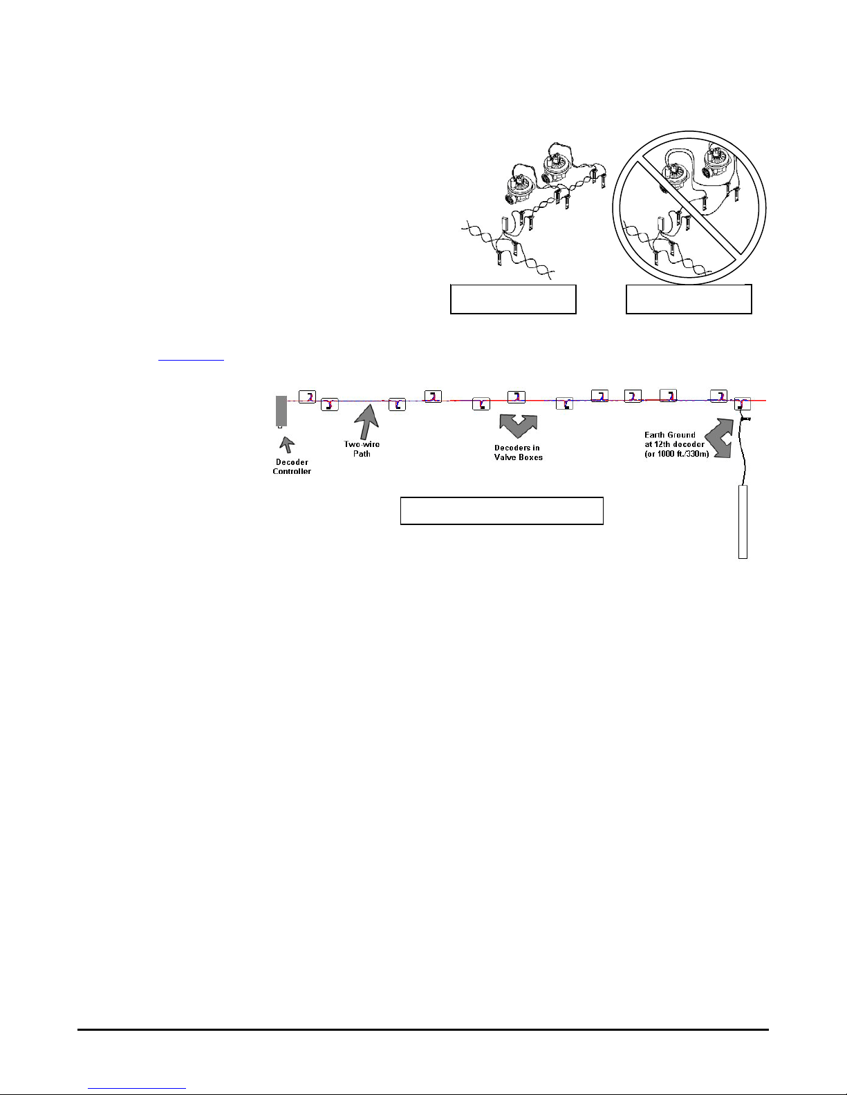
2. Select the decoder location (unless you are replacing an
existing decoder). Decoders should be within 100 feet/33m of
the solenoids they will operate. Decoders are waterproof, but
should be installed in a valve box to facilitate future service
and increase longevity.
3. Locate the 2-Wire path. These are the Red and Blue wires coming from the
controller. The wire path must be cut to insert decoder wiring,
unless you are replacing an existing decoder.
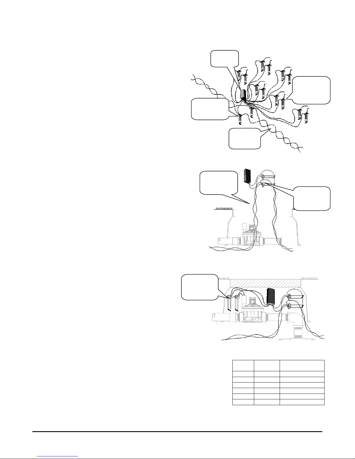
Be sure to leave enough slack in the wire path to allow easy
connection of the decoder, and to allow for contraction of wiring
due to temperature changes. Hunter recommends at least
5ft./1.5m slack for each decoder, to allow it to be removed from
the valve box completely for installation, service, and inspection.
4. Identify the color-coded wires on the decoder. The red & blue
wires connect to the red and blue wire path from the controller.
5. Strip the cut red and blue wire ends back approximately ½ inch
(12mm).
6. Twist the stripped red wire ends (the ends from the 2-wire path
and the decoder) together, and thread securely into the wire nut
for the DBRY-6 or equivalent waterproof connector. Seal in
accordance with the connector manufacturer’s instructions (insert threaded wire nut connection into waterproof grease,
and snap cap securely shut over wires).
7. Repeat with the blue wires: connect the blue end(s) from
the 2-wire path with the decoder, and secure in a
separate DBRY-6 or equivalent waterproof connector.
8. Each color-coded decoder output operates one or two
solenoids up to 150 feet/45m away (greater distances
are possible, but increase susceptibility to lightning
damage).
•Wire runs to the solenoids should be twisted pairs (if
solenoids are over 20 ft./7m from decoder) of at
least 18 AWG (1mm dia.) wire. The twist in the wire
is important, because it is an aid in lightning and
surge suppression.
Connect each color-coded station output to the desired solenoid(s) as follows:
•The non-insulated bare copper wire is the decoder’s grounding wire and is only used on selected decoders. If the
plan does not specify otherwise, ground at least every 12th decoder
module in each two-wire path, OR every 1000 ft/330m of wire, whichever
is first.
9. Strip back and connect the two black wires from the decoder to the solenoid
leads for the first station. Insert and seal connections with DBY or equivalent
waterproof connectors.
Note: Each ICD output may operate two solenoids simultaneously. The
solenoids must be connected in parallel, rather than in series. Each decoder
Output
Color
Genesis/VSX/IDS
Serial number
1
Black
xxxxxxx1
2
Yellow
xxxxxxx2
3
Green
xxxxxxx3
4
White
xxxxxxx4
5 Orange -
6
Purple
-
DBY,
solenoid
connections
Leave slack
in wire for
service!
DBR-6, red
& blue wire
connections
Red &
Blue 2-
Wire path
Serial
Number
Output wires
to solenoids
(DBY
connectors)
2-wire path
DBR-6
connectors

Hunter Industries
1940 Diamond Street •San Marcos, California 92078 •TEL (1) 760-744-5240 •Field Services (800) 248-6561 •FAX (1) 760-591-9582 •
www.hunterindustries.com •www.huntergolf.com April, 2010
3
output wire should make a three-way connection, with one wire from each of the two solenoids.
Decoder outputs never use a “common” wire.
10. If the decoder is to be ungrounded, fold the bare copper wire
out of the way. If the decoder is to be grounded (every 12th
decoder or 1000 ft/330m, whichever is first, including last
decoder in the wire path), connect the bare copper
12AWG/2mm dia. ground wire from the decoder to the wire
attached to the appropriate earth grounding hardware, with
a DBR-6 waterproof connector or approved clamp.
Earth Ground: Generally, use an 8’/2.5m rod, or
4”x36”/100mmx1m copper plate (Paige Electric Model
182201 or equal), inserted in the earth in accordance with
the manufacturer’s instructions.
The wire connecting the grounding hardware should be connected
at right angles to the two-wire decoder path, with the ground
hardware at least 8 ft/2.5m away from the two-wire path. There
should be no sharp bends or kinks in the copper ground wire leading to the earth ground hardware. For additional information on earth
grounding in high-lightning environments, consult the American Society of Irrigation Consultants web site, Earth Grounding Guideline
100-2002 (www.asic.org).
11. Apply controller power and test.
12. Genesis, VSX, and IDS
decoder controllers: Enter
the decoder serial
number(s) to associate
them with a controller
station output. This can be
accomplished from either
the IDSCD software kit, or
directly from the keypad on
these field controllers.
Consult the software or
controller documentation
to complete programming
and testing.
Top View of Decoder Wire Path
Correct
Incorrect
This manual suits for next models
1
Table of contents
Other Hunter Media Converter manuals