manuals.online logo
Brands
  1. Home
  2. •
  3. Brands
  4. •
  5. HUSTLER
  6. •
  7. Lawn Mower Accessories
  8. •
  9. HUSTLER 125223 User manual

HUSTLER 125223 User manual

125176 A 1 of 10
Dump From Seat Kit Instruction Number 125176
Part Number 125223
Packing List
This kit is for side catcher 125225. This kit is intended to be a permanent installation. Listed below are parts included in
this kit. If any parts are missing or damaged, please contact Excel Parts Department. Retain these instructions for
replacement parts.
INDEX NO. PART NO. DESCRIPTION QTY
1 125117-3 SWITCH MOUNT PLATE, 1
2 554995 SWITCH COVER 1
3 000331 WIRE TIES, SMALL 3
4 055939 CS .250-20 X 0.75 HX G5 ZY 2
5 768515 FW 0.281 SAE 2
6 601982 CN .250-20 X .150 MAX THK 2
7 607352 SAFETY DECAL 1
1
345 6
2
7
2 of 10 125176 A
Safety and Instruction Decals
The decals are designed to give the operator brief information needed in the daily operation and service of the mower.
These decals are not intended to be used in place of this manual but instead are to be used as an extension of this
manual. These decals should not be removed or obliterated. Replace these decals if they become unreadable.
It is the owner’s responsibility to make certain that the operators and mechanics read and understand this
manual and all decals before operating this mower.
It is also the owner’s responsibility to make certain that the operators and mechanics are qualified and
physically able individuals, properly trained in the operation of this equipment.
All operators and mechanics must become familiar with the safe operation of the equipment, operator
controls and decals.
Never let children or untrained people operate or service the equipment. Local regulations may restrict the
age of the operator.
The owner/user can prevent and is responsible for accidents or injuries occurring to themselves, other
people or property.
The owner should also ensure that the operators/mechanics know that they are responsible for their own
safety as well as the safety of other persons within the vicinity. Remember, the operator is responsible for
accidents or hazards occurring to other people or their property.
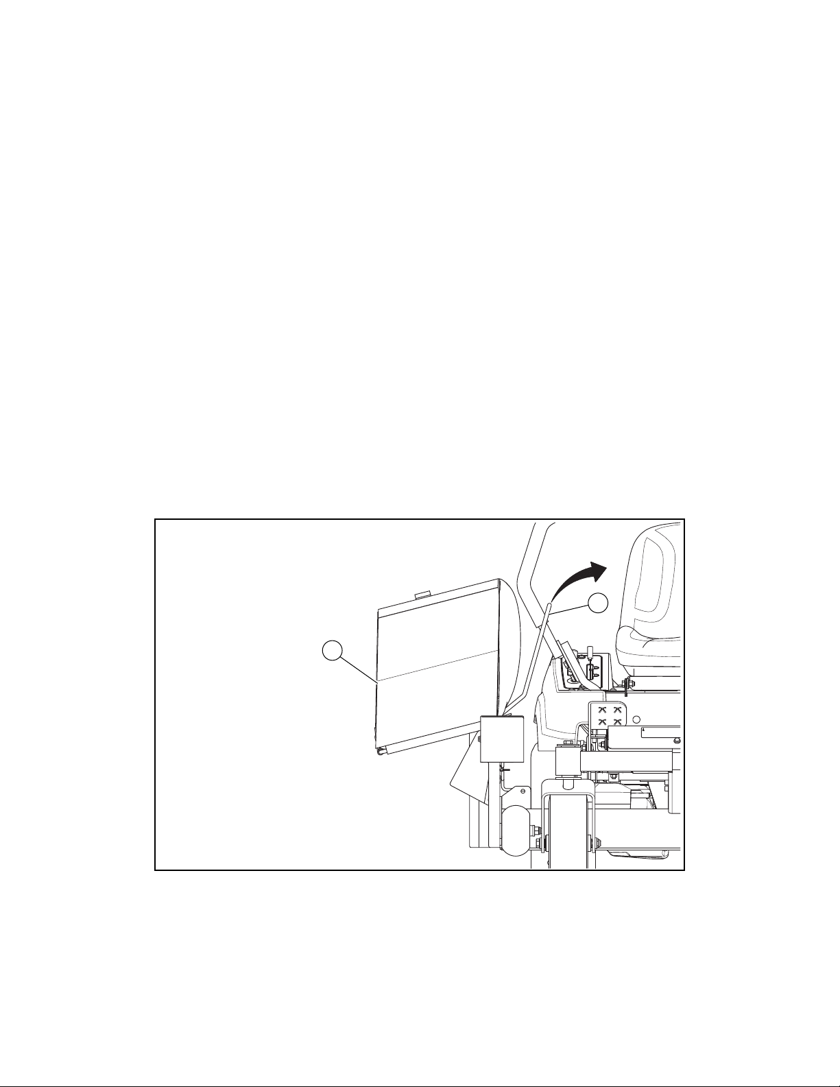
Refer to the mower’s operator’s manual for illustrations showing the various safety decals that are located on the mower.
A brief explanation, for those requiring one, is shown to help the operator understand the meanings of these decals.
WARNING
Specific safety warning decals are located on the equipment near the immediate areas of potential hazards.
These decals should not be removed or obliterated. Replace them if they become non-readable.
FIG. 1
607352
WARNING: Thrown Objects!
Never operate with catcher
bag in raised position.
Disengage the deck clutch
switch before raising the
catcher bag.
125176 A 3 of 10
Assembly
1. Park the mower on a solid, level surface; set the park brakes; shut-off the engine; and remove the ignition key.
(Disconnect the negative battery cable.)
2. Remove the catcher bag. Fig. 2
3. Remove the top set of existing hardware from the catcher plate as shown. Fig. 3
FIG. 2
FIG. 3
INDEX NO. DESCRIPTION
1 CATCHER BAG
2 CATCHER PLATE
2
1
INDEX NO. DESCRIPTION
1 CATCHER PLATE
2 CB .250-20 X .625 ZNYC
FW 0.281SAE
NT .250-20 HXZY NL
1
2
4 of 10 125176 A
4. Attach the switch plate to the catcher plate with the existing hardware. Fig. 4
5. Attach the switch wire harness to the backside of the catcher plate with the wire ties in the first two places as
shown. Do not install the rear wire tie at this time. Fig. 5
6. Slide the switch cover into place and secure with the hardware provided. Fig. 6
7. Locate and unplug the mower wiring harness connector from the deck clutch switch.
FIG. 4
FIG. 5
FIG. 6
INDEX NO. DESCRIPTION
1 SWITCH PLATE
2 CATCHER PLATE
3 CB .250-20 X .625 ZNYC
4 FW 0.281 SAE
5 NT .250-20 HX ZY NL
4
2
4
1
5
5
3
INDEX NO. DESCRIPTION
1 SWITCH PLATE
2 CATCHER PLATE
3 CLIP NUT
4 WIRE TIE
32
1
4
3
INDEX NO. DESCRIPTION
1 SWITCH PLATE
2 SWITCH COVER
3 CS .250-20 X 0.75 HX G5 ZY
4 FW 0.281SAE
5 CN .250-20 X .150 MAX THK
3
4
2
1
5
5
43
125176 A 5 of 10
8. Locate the orange wire with the red stripe. Cut the orange wire with the red stripe about 5” from the connector. Strip
1/4” of the covering from each side of the cut wire. Fig. 7
9. Locate the red wire connector on the dump from seat kit wire harness. Insert the orange/red wire that is coming
from the deck clutch switch harness connector into the connector on the red wire and crimp securely. Fig. 7
10. Insert the orange/red wire coming from the mower wire harness into the connector on the black wire coming from
the dump from seat kit wire harness and crimp securely. Fig. 7
11. Coil the excess DFS wire harness from the DFS switch. Secure with the wire tie. Fig. 8
FIG. 7
WARNING
Make sure to leave enough of the wire harness loose for full range of moving the deck through different
cutting heights.
FIG. 8
INDEX NO. DESCRIPTION
1 CATCHER PLATE
2 DECK CLUTCH SWITCH
3 DECK CLUTCH PLUG
4 ORANGE WIRE WITH RED STRIPE
5 SWITCH WIRE HARNESS
6 RED WIRE
7 BLACK WIRE
3
4
2
4
1
5
7
6
The orange wire with
the red stripe is in this
location on the deck
clutch connector.
INDEX NO. DESCRIPTION
1 WIRE TIE
2 CATCHER WIRE HARNESS
2 CATCHER DUMP SWITCH
2
1
3
6 of 10 125176 A
12. Remove the excess material from the catcher washer to allow the bag assembly to pivot for dumping.
IMPORTANT: Do not remove too much material. Make sure no burrs exist on the catcher washer. Fig. 9
13. Raise the catcher chute to the upright position. Fig. 10
FIG. 9
FIG. 10
INDEX NO. DESCRIPTION
1 CATCHER BAG
2 CATCHER WASHER
3 SWITCH STOP
2
1
3
Remove excess
material
INDEX NO. DESCRIPTION
1 CATCHER PLATE
2 CATCHER CHUTE 2
1
125176 A 7 of 10
14. Install the catcher bag. Make sure the switch stop is correctly inserted into the DFS switch assembly. Fig. 11
15. Connect the negative battery cable.
Check the Catcher Switch.
16. From the operator’s position, place both steering control levers in the park brake position. Start the engine and allow
it to warm up to operating temperature.
17. Make sure the surrounding area is clear of bystanders. Engage the deck clutch switch. Raise the handle on the
catcher bag toward the seat. Make sure the deck clutch disengages. Fig. 12
18. Lower the handle on the catcher bag to make sure the deck clutch engages. Fig. 12
NOTE: During normal operation it is recommended the operator disengage the deck by depressing the deck clutch
switch. The mower can be driven away from clippings and the operator can lower the bag into operating position.
19. The mower is ready for use.
20. To convert the mower to side discharge remove the catcher bag. The catcher discharge chute will automatically
drop into place. The mower is ready to operate in the side discharge mode.
FIG. 11
FIG. 12
INDEX NO. DESCRIPTION
1 CATCHER BAG
2 CATCHER CHUTE
3 SWITCH STOP
4 SWITCH ASSEMBLY
32
1
4
INDEX NO. DESCRIPTION
1 CATCHER BAG
2 CATCHER HANDLE
3 STEERING CONTROL LEVER
4 DFS SWITCH
3
2
1
4
8 of 10 125176 A
Operating
When the catcher is in operating position both switch plungers are fully depressed. Fig. 13
In the operating mode the bag presence switch and the bag closed switch are fully depressed. In the
dumping mode the bag closed switch is disengaged. The deck will automatically disengage.
NOTE: During normal operation it is recommended the operator disengage the deck by depressing the deck clutch
switch. The mower can be driven away from clippings and the operator can lower the bag into operating position.
If you continue to catch grass after the dust baffle has deflated you may need to remove blockage that has
clogged the deck. Fig. 14
Remove bag assembly from catcher mount after the blades have stopped. Use a stick to clear the discharge
area. Never use your hand to clear debris from the discharge area.
FIG. 13
INDEX NO. DESCRIPTION
1 SWITCH STOP
2 BAG CLOSED SWITCH
3 BAG PRESENCE SWITCH
11
22
Catcher bag in operating position
Catcher bag in dumping position
3
3
DANGER
Stop the engine before removing the grass catcher or unclogging the discharge chute. Never clear the
discharge chute with the engine running. Turn off the engine and be sure the blades have stopped before
cleaning. Use a stick to clear a plugged discharge area.
Never use your hand!
125176 A 9 of 10
The air flow dust baffle inflates during operation. The air flow dust baffle begins to deflate as the catcher bag fills. Empty
the catcher bag before the air flow dust baffle completely deflates. Fig. 14
Trouble Shooting
Mower will not start:
Check that the negative battery cable is connected.
Check that the steering levers are in the outward (park) position.
Check that the deck clutch switch is fully depressed (off position).
Contact your dealer.
Deck will not engage:
Inspect catcher bag assembly to insure it is seated properly and switches are engaged.
Clean grass clipping and other debris from unit. Never use high pressure water to clean the mower
especially around the switches as damage can occur.
Inspect all wires for damage or loose connections.
Check the connector to the deck clutch switch to ensure it is pushed all the way onto the switch.
Contact your dealer.
Deck will not disengage while dumping:
Turn machine off and remove the key.
Inspect switches to ensure hardware has not become loose or switches have become damaged.
Never operate catcher with switch cover plate removed.
Contact your dealer.
FIG. 14
INDEX NO. DESCRIPTION
1 AIR FLOW DUST BAFFLE
2 CATCHER BAG
1
1
22
Deflated Inflated
10 of 10 125176 A
Blades do not turn when engaging deck:
Inspect catcher bag assembly to insure it is seating properly and engaging switches.
Clean grass clipping and other debris from unit. Never use high pressure water to clean unit, especially
around the switches as damage can occur.
Inspect all wires and switches for damage or loose connections.
Contact your dealer.
Bag not filling all the way:
Slow down. Driving too fast for conditions may result in deck becoming clogged.
Cut less material at a time. See Excel Side Catcher Manual (P/N 125225) for further operation instructions.
Use standard blades that came with unit. Keep blades sharp. Check deck for being level with a ¼” pitch from
front to rear.
Check for damaged bag. Replace any worn or damaged parts.
Contact your dealer.
Unable to rotate bag assembly for dumping clippings:
Inspect bag assembly for correct removal of tab. See steps 12 & 13, Fig. 9 & Fig. 10.
Contact your dealer.
FIG. 15
INDEX NO. DESCRIPTION
1 CATCHER HANDLE
2 CATCHER BAG
1
2

Other HUSTLER Lawn Mower Accessories manuals

HUSTLER 940353EX User manual

HUSTLER

HUSTLER 940353EX User manual

HUSTLER X-ONE User manual

HUSTLER

HUSTLER X-ONE User manual

HUSTLER 67062 User manual

HUSTLER

HUSTLER 67062 User manual

HUSTLER BAC-VAC User manual

HUSTLER

HUSTLER BAC-VAC User manual

HUSTLER 939769 User manual

HUSTLER

HUSTLER 939769 User manual

HUSTLER 121696 User manual

HUSTLER

HUSTLER 121696 User manual

HUSTLER 928739 User manual

HUSTLER

HUSTLER 928739 User manual

HUSTLER 121482 User manual

HUSTLER

HUSTLER 121482 User manual

HUSTLER Zevo User manual

HUSTLER

HUSTLER Zevo User manual

HUSTLER 121505 User manual

HUSTLER

HUSTLER 121505 User manual

HUSTLER X-ONE User manual

HUSTLER

HUSTLER X-ONE User manual

Popular Lawn Mower Accessories manuals by other brands

Husqvarna HCS9, HCS13 Operator's manual

Husqvarna

Husqvarna HCS9, HCS13 Operator's manual

Husqvarna MZ54 Operator's manual

Husqvarna

Husqvarna MZ54 Operator's manual

Cub Cadet 19A30056100 Operator's manual

Cub Cadet

Cub Cadet 19A30056100 Operator's manual

Poulan Pro 532402705 owner's manual

Poulan Pro

Poulan Pro 532402705 owner's manual

Husqvarna PZ 60 installation instructions

Husqvarna

Husqvarna PZ 60 installation instructions

Stiga 85 COMBI owner's manual

Stiga

Stiga 85 COMBI owner's manual

Stiga 85 COMBI owner's manual

Stiga

Stiga 85 COMBI owner's manual

Craftsman Sun Shade 486.24226 owner's manual

Craftsman

Craftsman Sun Shade 486.24226 owner's manual

Snapper 0-50576 Operator's manual

Snapper

Snapper 0-50576 Operator's manual

Toro 115-4917 installation instructions

Toro

Toro 115-4917 installation instructions

Snapper 1695064 Operator's manual

Snapper

Snapper 1695064 Operator's manual

Snapper EC13V parts manual

Snapper

Snapper EC13V parts manual

Husqvarna H348SG owner's manual

Husqvarna

Husqvarna H348SG owner's manual

Poulan Pro 532140602 owner's manual

Poulan Pro

Poulan Pro 532140602 owner's manual

Husqvarna CET42 instruction manual

Husqvarna

Husqvarna CET42 instruction manual

Toro 161-4520 installation instructions

Toro

Toro 161-4520 installation instructions

Simplicity 1692149 Illustrated parts list

Simplicity

Simplicity 1692149 Illustrated parts list

Yard-Man ZYJ-1417A Operating manual and parts list

Yard-Man

Yard-Man ZYJ-1417A Operating manual and parts list

manuals.online logo
manuals.online logoBrands
  • About & Mission
  • Contact us
  • Privacy Policy
  • Terms and Conditions

Copyright 2025 Manuals.Online. All Rights Reserved.