Huvema HU 50 H User manual

HU 50 H
OPERATION MANUAL

2
Contents
1. Safety Instruction
2. Working Environment of Machine
3. Purpose and Structure of Machine
4. Main Parameter of Machine
5.Transmission System of Machine
6. Operation of Machine
7.Adjustment of Machine
8. Cooling and Lubrication of Machine
9.Bearing List of Machine
10.Transportation, Installation and Trial Run
11. Maintenance of Machine
12. Simple Malfunction & Obviation
13. Electrical System of Machine
14. Adjustment of universal swivel head

3
1. Safety Instruction
1.1 General safety rules
Operator must read the instruction carefully before operating the
machine, and the manager of safety department should assure the operator
knows the requirements well.
WARNING: Never contact the cutters and other driving parts by hands if
they are still moving.
1.1.1 The operation, maintenance and repair of the machine must be done by
qualified person who have been trained to have the ability to forecast the potential
risks. Only safety-conscious persons who are fully aware of the risks can operate the
machine.
1.1.2 To those people who assemble, operate, or maintain the machine must be
confirmed to have read and understood the operating instructions.
1.1.3 After stopping the machine, the tool will still run for a period of time due to
inertia, do not open the tool guard and touch the tool by hands before it comes to a
stop.
1.1.4 Do not detach or modify any part of the safety guard. The machine should
be disconnected from the automatic supply during maintenance or repair.
1.1.5 Assign special persons to operate, maintain and adjust the machine.
1.1.6 Operate the machine in technically perfect condition. Only relative
professional can completely repair the machine.
1.1.7 Stop the machine immediately if abnormal phenomena appears, check and
repair the machine by professional in time.
1.1.8 Convey the machine with the hoisting equipment, which is of enough load
capacity.
1.1.9 Observe all safety instructions and warnings attached to the machine, make
sure they are always complete and perfectly legible.
1.1.10 Do safety inspection before operating the machine. Ensure the stroke limit
switches, stop block and emergency stop button is safe and reliable.
1.1.11 Reinstall the removed guards and safety devices in place after maintaining
the machine.
1.1.12 Do maintenance or adjustment only after shutting off power source.

4
1.1.13 Always keep children away from the machine. Operator must be at least
18 years old.
1.1.14 Do not wear loose clothing, gloves, neckties or jewelry (rings, watches,
etc). Keep the sleeves and the edges of the work uniform tight. Always be sure to
wear safety goggles and wear safety shoes during operation.
1.1.15 Put the long hair into a safety cap during operation no matter the operator
is a man or a woman.
1.1.16 It is recommended to wear suitable hearing protection equipment if
necessary.
1.1.17 Provide adequate light around the machine, and keep the perimeter around
the machine dry, clean and in good order. In addition, do not place anything near
the machine; otherwise it becomes an obstacle during operation.
1.1.18 Do not remove the guards from their working place during operation.
1.1.19 Disconnect the automatic supply before leaving the machine.
1.1.20 Restart the machine only after the guards and safety devices are replaced
to their position and in their good function.
1.1.21 Do not place tools, work pieces, or other items, which is not in use on the
machine, especially on the moving parts.
1.1.22 Clamp workpiece and tools completely and reliably and take off the
wrench from chuck before starting the spindle running.
1.1.23 Stop the machine before adjusting the position of the coolant nozzles.
1.1.24 Do not use compressed air to remove dust and chips, deposit on the
machine, switchboard, control unit etc.
1.1.25 Both operators and the maintenance men should read the descriptions
carefully on the caution plate attached to the machine. They should observe the
OPERATION MANUAL during their work. During operation and maintenance,
care should be taken so that the caution plate is not dirtied or damaged.
1.1.26 Always bear in mind where the emergency stop button is so that you can
operate it without delay in case of an emergency.
1.1.27 Start the machine according to the starting procedures strictly.

5
1.1.28 Keep your hands away from the turning parts of the machine during
operation.
1.1.29 Do not remove the chips directly by hand, It is safer with proper tool to
remove the chips. Be sure to stop the machine when removing chips from the
machine.
1.1.30 Prior to starting test operation, read this manual carefully so as to be
familiar with this machine.
1.1.31 Contact the manufacturer if for some reason the OPERATION MANUAL
should become unreadable.
1.2 Additional Safety Rules for Mills
1.2.1 Read and understand the entire instruction manual before operating the
machine.
Warning: Failure to follow the instruction will result in serious injury.
1.2.2 Always wear approved safety glasses/suit while operating machine tool.
1.2.3 The machine must be grounded.
1.2.4 Before operating the machine, remove tie, rings, watches, other jewelry,
Keep the sleeves and the edges of the work uniform tight. Always be sure to
wear safety goggles and wear safety shoes during operation. Do not wear gloves
while operating machine tool.
1.2.5 Keep the floor around the machine clean and away from scrap materials, oil
and grease, etc.
1.2.6 Keep all guards of the machine securely in place at all times when working.
For maintenance purpose, use extreme caution to replace the guards immediately
after maintenance.
1.2.7 Make sure workpiece and cutter be fitted and clamped well, and make sure
the cutter doesn't touch the workpiece before starting up the machine.
1.2.8 Must shut off power supply before adjusting or maintaining the machine.
1.2.9 The operator must keep clear-minded when operating the machine and pay
attention to what he is doing. It is not allowed to operate the machine when the
operator is tired, after drinking or taking medicines.
1.2.10 Use tools properly. Don't force a tool or an attachment to do work which
was not designed. Sharp tools should be used. Deformed or dull tools should not be
used.

6
1.2.11 Make certain the motor switch is in OFF position before connecting the
machine with power supply.
1.2.12 Never attempt to operate or adjust the machine when the procedure is not
understood.
1.2.13 Always stop the machine before adjusting the position of the cooling
nozzle.
1.2.14 Operator should change machining position on the table frequently in order
to prolong the life of the machine.
1.2.15 Lubricate the machine in time according to the lubricating demand.
1.2.16 Keep the electrical elements clean, do not clean the electrical elements with
kerosene or gas.
1.2.17 Be sure the spindle rotation of the machine comes to rest before changing
spindle speed.
1.2.18 It is forbidden to process flammable and explosive metal, for example:
pure aluminum, magnesium and so on.
1.2.19 The machine should never be used in flammable, explosive or humid
environment.
1.2.20 Make sure the operating site should keep well ventilated. It is
recommended that ventilation equipment should be provided on the operating site.
2. Working Environment of Machine
2.1 The milling machine is designed for operating on the site:
—The height above sea level doesn’t exceed 1000m.
—The ambient temperature range doesn’t exceed 5℃~40℃.
—The relative humidity doesn’t exceed 50% within+40℃and 90% within+
20℃.
—Transportation temperature range is within -25℃~+55℃
__The light in the working environment should not be lower than 500 lux.
2.2 Do not use the machine in an environment of electric dirt, explosion, metal
fretted, gas and steam which can destroy insulation.
2.3 Do not use the machine in an environment of impact and vibration.

7
3. Purpose and Structure of Machine
The universal swivel head milling machine is designed for milling on general
metal workpiece.
Warning: Do not process flammable and explosive metal, e.g. pure
aluminum and magnesium, etc.
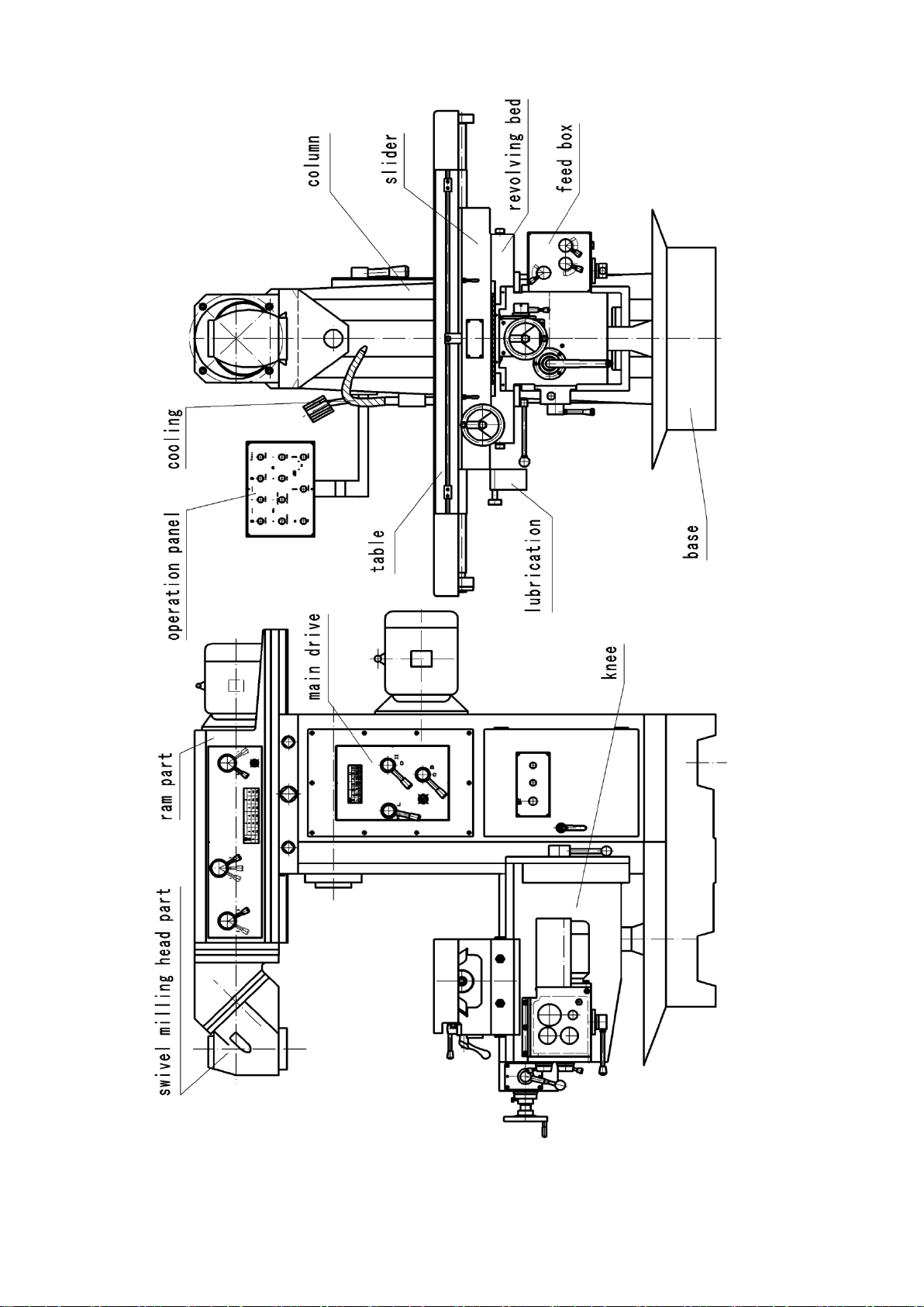
The universal swivel head milling machine consists of universal swivel head,
base, column, knee, table, revolving bed, main drive structure, feed box, ram,
coolant, lubrication, electrical system and so on.
The structure of the machine: (Figure.1)
3.1 The column is fixed on the base with screws.
3.2 Knee is in front of the column, and connects with the column through
rectangular guideways, which can rise and lower along vertical guideway.
3.3 Revolving bed connects with knee through rectangular guideways. Table
connects with slide through dovetail guideways. Worktable and the slide can be
moved through lead screw and nut.
3.4 Main transmission adopts gears drive structure.
3.5 The feed box is fixed at the bottom & right of revolving bed, and it is driven
directly by motor,
3.6 The coolant system consists of coolant pump, cooling tube and tank in the base
and so on.
3.7 Lubrication system consists of oil immersed splash lubrication, lubrication pump
and hand pump and so on.
3.8 Operation panel is on the left of the column, which enables convenient
operation.
The table is moved by hands or power, the power of feed box is provided by
only one motor. The feed box has twenty-four kinds of speed steps and three kinds
of rapid speed. Main transmission adopts gears structure, high efficiency, big torque,
enlarges speed change range, so enlarge the machining range.
3.9 Rotation of table: Loosen the four screws at two sides of the revolving bed, then
turn the table forcibly in target position.

8
Figure.1

9
4. Main Parameter of Machine
No.
Specification
Parameter
1
Spindle taper
ISO50
2
Distance between spindle axis
and table surface.
0~400mm (0 ~ 15 - 3/4")
3
Distance between spindle axis
and surface of ram
175mm (6 - 7/8")
4
Spindle speed
58 ~ 1800 r.p.m (50Hz);70 ~ 2160 r.p.m (60Hz)
60~1750 r.p.m (50Hz) (universal swivel head)
72~2100 r.p.m (60Hz) (universal swivel head)
5
Table size
1320mm×360mm (51 - 31/32"×14 - 3/16")
6
Table travel
( X,Y, Z )
1000mm (39 - 3/8") (longitudinal)
300mm (11-13/16") (cross)
400mm (17 - 3/4") (vertical)
7
Rotary angle of table
±35°
8
Longitudinal, cross, vertical
table power feed speed
22 ~ 420 mm/min (7/8" ~ 16-1/2" )(50Hz) (X)
22 ~ 393 mm/min (7/8"~ 15-1/2" )(50Hz)(Y)
10 ~ 168 mm/min (3/8"~ 6-5/8" )(50Hz) (Y)
rapid feed 1290mm/min (50-3/4") (50Hz) (X)
rapid feed 1205mm/min (47-1/2") (50Hz)(Y)
rapid feed 513mm/min (20-1/8") (50Hz)(Z)
26 ~ 505 mm/min (1" ~ 19-7/8" )(60Hz) (X)
26 ~ 470 mm/min (1"~ 18-1/2" )(60Hz)(Y)
12 ~ 200 mm/min (1/2"~ 7-7/8" )(60Hz) (Y)
rapid feed 1548mm/min (60-15/16") (60Hz)(X)
rapid feed 1446mm/min (57") (60Hz) (Y)
rapid feed 615mm/min (24-1/4") (60Hz)(Z)
9
Ram travel
500mm (19 - 5/8")
10
Main motor power
4 kW
11
Overall dimension(L×W×H)
1900 mm×1720 mm×1950
74 - 7/8"×67 - 3/4"×76- 3/4"
12
Net weight
2200 kg
The specifications are subject to modification and improvement without notice.

10
5.Transmission System of Machine (Figure.2)
5.1 Universal swivel head
Spindle of universal swivel head drive system is installed in the ram and driven by a
flange motor.
5.2 Spindle transmission system
Spindle drive system is installed in the column and driven by a flange motor. The
motor connects with a drive shaft and passes power to the spindle through gears and
sliding gears.
Main transmission: main motor→drive shaft→gears and sliding gears→spindle.
5.2 Table feed transmission system
Power is produced by manual operation or automatic operation, Power is passed
to lead screw and nut to realize longitudinal and cross feed of table.
5.3 Knee
Knee can rise and fall vertically through two bevel gears. Power is passed to lead
screw and nut to realize vertical feed of table.
5.4 Ram
Slack the locking handle on the right of ram, turn gear shaft on the right of the
ram to adjust ram in the desired position, tighten the locking handle finally.

11
Figure.2

12
6. Operation of Machine
6.1 Please read the manual carefully before operating the machine, then make
familiar with structure of the machine, function of each hand lever, and buttons on
the operation panel, coolant & lubricating system and electrical system and so on.
(Figure.3)
6.2 Check whether each locking structure is normal before starting the machine,
and whether ground wire is right and reliable.
6.3 Switch on power switch, check whether electrical switch is flexible and
reliable. Operation panel situates on the left of the column. The pushbuttons on the
operation panel have visual symbols, so operation is convenient. There is inching
button on the right side of the column, so change spindle speed well.
6.4 Speed change of spindle.
Press inching turning “T”button on the right side of the column first, then adjust
three handles (19) in target position according to the illustration of the speed plate.
Spindle speed change of universal swivel head: Adjust three handles (7) in target
position according to the illustration of the speed plate.
6.5 Start motor of the feed box first, then adjust handle (1) in “STOP” position,
adjust handles (2) at target speed. Table will rapidly feed when handle (1) is situated
in “RAPID”position.
6.6 Longitudinal feed of table
6.6.1 Longitudinal power feed of table: First loosen locking handle (4), and adjust
the handle (5) in LEFT or RIGHT, NEUTRAL position, which will realize the
longitudinal power feed.
6.6.2 Longitudinal manual feed of table: First loosen locking handle (4), and adjust
the handle (5) in MANUAL position, then turn handwheel (13) directly to realize
longitudinal manual feed of table.
6.7 Cross feed of table
6.7.1 Cross manual feed of table: First loosen locking handle (16), adjust the
handle (3) in “NEUTRAL”position, then turn handwheel (21) directly to realize
cross manual feed of table.
6.7.2 Cross power feed of table: First loosen locking handle (16), must draw out
the knob at the end of handle (3) before adjusting the handle (3) up or down, which
will realize the cross power feed.

13
6.8 Vertical feed of table
6.8.1 Vertical manual feed of table: First loosen locking handle (12), adjust the
handle (17) in “NEUTRAL”position, then turn handwheel (18) directly to realize
vertical manual feed of table.
6.8.2 Vertical power feed of table: First loosen locking handle (12), adjust the
handle (17) up or down, which will realize the vertical power feed.
WARNING: Must take off the crank handle (18) when crank handle (18) is not
used.
6.9 Swivel table
First loosen the locking screw (20) at two side of the revolving bed, then turn the
table forcibly in target position, tighten the locking screw (20) finally.

14
F
Figure.3

15
7. Adjustment of Machine
7.1 Adjustment of backlash of the spindle bearings. (Figure.4)
Backlash of spindle bearings has been adjusted well before the machine left the
factory. Long time use of machine causes natural wear of spindle bearings and
backlash will increase. Please ask professional to adjust it.
Remove cover ①on the right side of the column first. First make claws of lock
washer flat under the round nut, adjust round nut (2) to make backlash of spindle
proper, then make claws of lock washer turnup, then fix cover (1).
7.2 Adjustment of longitudinal and cross gibs of the table
7.2.1 Longitudinal gib adjustment: First loosen screw ①of small end of gib, then
adjust screw ②of big end of gib in proper position until a slight drag is felt while
moving the table, tighten screw ①properly finally. (Figure.5.a).
7.2.2 Cross gib adjustment: Remove scrap iron wiper ②, loosen screw ①on one
end of gib, adjust screw ③on the other end of gib to proper position until a slight
drag is felt while moving the table, then fix scrap iron wiper ②. (Figure.5.b)
7.2.3 Adjust the clearance between the knee and vertical guideway.
Remove scrap iron wiper ③, loosen screw ①on small end of gib, then adjust
the screw ②on the big end of gib in proper position until a slight drag is felt while
moving the table, fix scrap iron wiper ③finally. (Figure.5.c)
7.2.4 Adjustment of the backlash between the longitudinal direction lead screw
and nut.(Figure.6)
Too big clearance between the lead screw and nut will affect machining
accuracy.
Loosen locking screw first, adjust adjusting worm properly, tighten locking
screw.
7.2.5 Adjustment of the backlash between the cross direction lead screw and nut
Directly adjust round nut under the revolving bed until a slight drag is felt while
moving the table along the rectangular slides.

16
Figure.4
Figure.5

17
longitudinal direction
Figure.6
8. Cooling and Lubrication of Machine
8.1 Coolant is send to nozzle through pipe. Adjust the nozzle to spray coolant to
cutting area and cutter exactly. Coolant is contained in base of the machine.
8.2 Cooling system
Coolant system consists of coolant pump, coolant tank in the base of the
machine, orientable and adjustable nozzle and so on.
The valve is used to control the flow of coolant spraying to the cutting area
exactly. Coolant is contained in the base of the machine.
MSDS Safety information
Name: JN-8 water-miscible antirust cutting liquid
Ingredients: Non hazardous ingredient
Skin: No
Ingestion: No
Carcinogenicity: No
Appearance and odor: semi- transparence liquid /no odor .
Antirust property : first-class gray cast iron
single piece (drop) 48h eligible; fold pieces 8h eligible
rust test: 55±2℃cast iron 48h eligible; aluminum 4h eligible
eliminate foam: eligible
PH value: 8.5 extensive test paper

18
Surface tensility:<40dyn/cm
PB value:>700
μ<0.083
Skin: NO
Ingestion: NO
Carcinogenicity: NO
Effects of exposure: skin: slight irritation.
Explanation of Carcinogenicity: none.
First aid: eyes: flush thoroughly. skin: wash w/soap & water
ingestion: if >1/2 liter (pint), immediately give 1-2 glasses of
water & call a physician.
Inhalation: No volatilization at normal temperature, but at high temperature will
volatilize hydrocarbon, after inhalation, call a physician.
Extinguishing media: No.
Handling and Disposal
Spill Release Procedures: if a little, absorb on sawdust, or shovel up; If a great lot,
prevent spill from entering sewers, drains. soils, then reclaim spill through an
approved recycling facility at any government approved waste disposal facility.
1. Cutting liquid can not be directly drained, it should be reclaimed
and processed under the laws and regulations.
2. Vapor of coolant which may have a influence to health may arise
when the temperature of the tools or the spindle rotation speed is high. So
care should be taken that the operating site must kept well ventilated. It is
recommended that ventilation equipment should be provided on the
operating site.
8.2 Lubrication
To a great extent, life of machine depends on scientific lubrication.
8.2.1 Lubricating oil must be clean, nonacid, anhydrous and no hard solid and so
on.
8.2.2 Main gears adopt automatic force lubricating structure. Reversible cycloidal
lubricating pump is installed in the cavity of the column, lubricating pump will start
when main motor starts. Lubricating oil is sprayed on gears. Gear box adopts oil
immerged splashing lubrication.

19
In order to lubricate machine well, lubricating oil tank should be cleaned regularly
once 3 months at the beginning, once every half a year later.
8.2.3 Please add oil when oil surface is lower than oil scale.
8.2.4 Lubricate lead screws, saddle-table guideway, saddle-knee guideway,
knee-column guideway, etc, four times per shift.
8.2.5 Bearing cover of milling holder of hanger adopts dribbing automatic
lubrication, should often add oil and clean it.
Other parts which need lubrication have mounted oil cup, every shift must add oil
at least 4 times.
MSDS Safety information
Name: N.46 lubricating oil
Health Hazards Data
Ingredients: Non hazardous ingredient
Relative consistency: <1
Inhalation: NO
Skin: NO
Ingestion: NO
Carcinogenicity: NO
Effects of exposure: skin: slight irritation.
Explanation Of Carcinogenicity: none.
First aid: eyes: flush thoroughly. skin: wash w/soap & water
ingestion: if >1/2 liter (pint), immediately give 1-2 glasses of
water & call a physician. don't induce vomiting/give anything through mouth.
If unconscious, call a physician.
Fire and Explosion Hazard Information
Flash Point Text: 180℃
Extinguishing Media: CO2, form, dry chemical & water fog.
Hazard: PREVENT RUNOFF FROM FIRE CONTROL OR
DILUTION FROM ENTERING STREAMS, SEWERS OR DRINKING
WATER SUPPLY.
Physical/Chemical Properties
Solubility in Water: Negligible
Appearance and Odor: Dark amber liquid /no odor.

20
Reactivity Data
Stability Indicator: YES
Stability Condition to avoid: Extreme heat.
Materials to avoid: Strong oxidizers, combustible material.
Hazardous Polymerization Indicator: NO
Handling and Disposal
Spill Release Procedures: first, cut off fire source, if a little, absorb on sawdust, or
Shovel up; If a great lot, prevent spills from entering sewers, drains, soils, then
reclaim spill through an approved recycling facility at any government approved
waste disposal facility.
Warning: Waste oil should be reclaimed and processed under local laws and
regulations.
Table of contents
Other Huvema Power Tools manuals
Popular Power Tools manuals by other brands

Force
Force PT100942 Operator's manual

Chicago Pneumatic
Chicago Pneumatic CP825 Series instruction manual

Shop fox
Shop fox W1702 manual

Shock Line
Shock Line MA PREGI 35N1 Operating and maintenance instructions

STELLEN DOER
STELLEN DOER BLHD1 Operation manual

DUCTMATE
DUCTMATE REPEATER 4200 Operation and maintenance manual