BEAMEX MCS100 User manual
Instruction manual for
MODULAR CALIBRATION SYSTEM
Beamex®MCS100
Dear user,
We have made every effort to ensure the accuracy of the
contents of this manual. Should any errors be detected, we would
greatly appreciate to receive suggestions to improve the quality of
the contents of this manual.
The above not withstanding, we can assume no responsibility for
any errors in this manual or their eventual consequences.
We reserve rights to make modifications to this manual without
any further notice.
For the Beamex®MC5P Calibration host module, please refer to
separate user guide.
© Copyright 2011
BEAMEX OY AB
Ristisuonraitti 10
FI-68600 Pietarsaari
FINLAND
Tel +358- 10-5505000
Fax +358-10-5505404
Internet: http://www.beamex.com
8889000 / UEMCS100 / 000696

Trademarks
QCAL®is a registered trademark owned by Beamex Oy Ab.
Other trademarks are property of their respective owners.

Contents
Part A, About the MCS100 System
General Overview 2
Introduction …………………………………2
Unpacking and Inspection …..……………3
Service …………………………..………….3
Safety 4
The MCS100 Desktop System power
supply …………….……..……………….…5
MCS100 Desktop System 6
General ………………………..……………6
Environmental Specification ……..……6
Taking the Desktop System in use 7
Uninstalling and Installing Modules
in the Desktop System ……………..……..8
Internal Connections …………………...9
MCS100 Bench System 10
General ……………………………………10
Environmental Specification ……..….10
High Workstation …………………………10
Assembly Instructions for High
Workstations …………………………..11
Corner Unit ………………………………..13
How to Assemble the Corner Unit …..14
Low Workstation …………………………16
Assembly Instructions for Low
Workstations …………………………..16
Connecting the Workstation to
the Electrical Network ……………………18
Connecting the Workstation to
the Pressure Supply ……………………..18
Use of the Workstation…………………..19
Uninstalling and Installing Modules
in the Bench System …………………….20
Internal connections…………………..21
DS2 Data Switch Module………………..22
Connections……………………………23
Special Workstations …………………….25
Heavy-duty Workstation ……………...25
Electrical Trolley……………………….25

Part B, Main Supply Units
General 27
Warnings ……………………..….…………27
SU1 Main Supply Unit 28
Connections .……………………………….29
Operation …………………………….……..29

Part C, Assisting Modules
General 31
Warnings When Using
Pressure Modules ………………………..32
Additional Warnings When Using
High Pressure Modules ………………….33
Pressure Connections 34
Pressure Supply Modules 35
PS7 Pressure Supply Module …………..35
Operation ………………………………35
Connections……………………………35
Maintenance of the Pressure
Supply Modules …………………………..36
Pressure Output Modules 37
PO8C………………………………………38
Specifications ………………………….40
Warnings……………………………….42
Service …………………………………44
Selector Valve …………………………44
Operation ………………………………44
PO20 ………………………………………46
Operation ………………………………46
Connections …………………………...48
PO60, PO160 and PO250 ………………48
Operation ………………………………49
Connections ...…………………………49
Maintenance of the Pressure
Output Modules …………………………..50
Pressure Measurement Modules 51
Available Pressure Measurement
Module Types and Their
Measurement Ranges …………………….52
Installing and Uninstalling Pressure
Measurement Modules ……………………53
Removing a Pressure
Measurement Module ………………….53
Adding a Pressure
Measurement Module ………………….54
RTS24P Temperature/Resistance
Simulator Module 55
Operation……………………………………56
Installing and Uninstalling
the RTS24P Module……………………….56

Appendixes
Appendix 1,
Compatibility of MCS100
Workbench Table Frames
and Module Racks 58
Appendix 2,
Index 60

MCS100 User Guide 1
About the MCS100 System
Things discussed in Part A:
introduction to what MCS100 is and what the
parts of this User Guide concentrate on,
general presentation of the MCS100 Desktop
System,
general presentation of the MCS100 Bench
System and
how to install and take in use different type of
MCS100 Bench Systems.

MCS100 User Guide 2
General Overview
Introduction
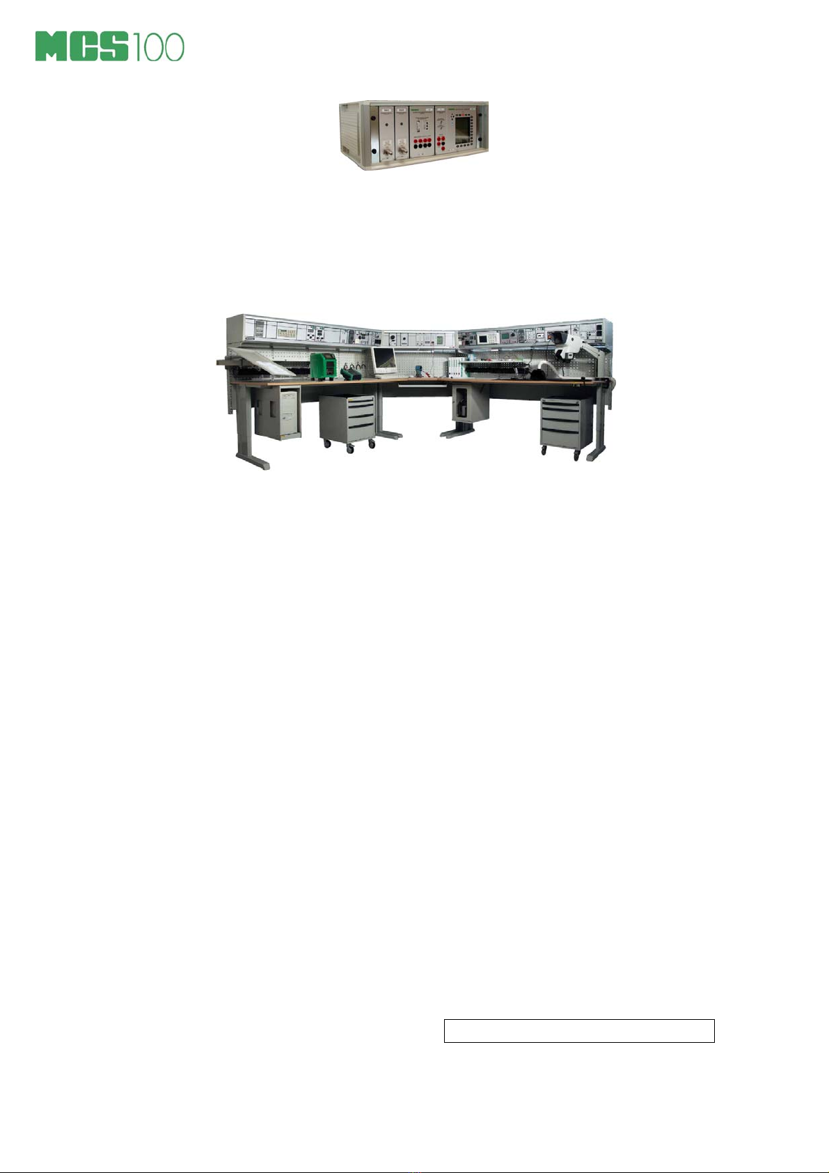
The MCS100 System is a Modular Calibration System for
calibration and maintenance of process instruments, like
transmitters, converters, temperature probes, recorders, indicators,
etc. The system is designed for instrument/electrical workshops and
laboratories.
The MCS100 comprises a Desktop System, a Bench System or an
Electrical Trolley. The modular construction of the system allows
the user to customize the MCS100 System to practically any
measurement and calibration application.
The modules in the MCS100 System can be grouped into four main
types:
1. Host modules (Calibrator modules):
MC5P Calibration host module
2. Assisting modules, divided into:
PO’s, i.e. Manual Pressure Output Modules,
PS’s, i.e. Manual Pressure Supply Modules,
PM’s, i.e. Pressure Measurement Modules and
RTS24P Temperature/Resistance Simulator module
3. POC6 Automatic Pressure Controller
4. Power supplies, measuring instruments, soldering stations and
other modules.
This manual includes a general presentation of the MCS100
System in part A.
Part B concentrates on the Main Supply Units for the MCS100
Bench system.
Part C concentrates on the Assisting modules (PO's, PS's, PM's
and RTS24P)
MC5P Calibration host module, POC6 Automatic Pressure
Controller, Power supplies, Measuring instruments and other
modules are covered in separate manuals.
Note
This manual includes a description of all the MCS100 Modular
Calibration Systems available, not only the system at hand.

MCS100 User Guide 3
Unpacking and Inspection
At the factory each new MCS100 System passes a careful
inspection. It should be free of scrapes and scratches and in proper
operation condition upon receipt. The receiver should, however,
inspect the unit for any damage that may have occurred during
transport. If there are signs of obvious mechanical damage,
package contents are incomplete, or the instrument does not
operate according to specifications, contact the purchasing sales
office as soon as possible.
The Modular Calibration System MCS100 is supplied with a general
instruction manual. The host modules (MC5P), the automatic
pressure controller (POC6), power supplies, measuring instruments
and other modules have their own manuals. All the modules
purchased with the MCS100 System are installed in the module
rack or in the base unit at the factory. Installation of additional
modules that are purchased later on is described in chapter
Uninstalling and Installing Modules in the Desktop System on
page 8 and chapter Uninstalling and Installing Modules in the
Bench System on page 20.
If you have to return a module or another part of the MCS100
System to the factory for any reason, include a detailed description
of the reason for the return.
Service
A module that requires service or calibration must be carefully
packed and should be accompanied with a letter or note with the
following information:
User’s name
User’s address
Module name
Serial number
Description of the problem
If the module requires calibration, it must be stated in the enclosed
letter.

MCS100 User Guide 4
Safety
High voltage is dangerous. Getting into contact with high
voltages can result in serious injuries, even death.
The power cable plug shall only be inserted into a socket
with a protective earth contact in accordance with local
electrical rules. The protective action must not be negated by
the use of an extension cord without a protective conductor
(grounding).
Make sure that only fuses with the required rated current and
for the specified type (normal blow, time delay etc.) are used
for replacement. The use of repaired fuses and the short
circuiting of fuse holders must be avoided.
Capacitors in the power supply unit may still be charged
even if the power cable has been disconnected.
Sometimes it is necessary to carry out measurements inside
the module rack with the mains power on. Make these
measurements with extreme care and remove the power
cable immediately after the measurements are completed.
The operation should be carried out by a skilled person who
is aware of the hazard involved.
In the occasion that a module is no longer operating safely,
the module must be taken out of use and precautions must
be taken against accidental use
Safe use is no longer possible in the following cases:
- When the module has a clear visible damage
- When the instrument is not functioning as expected
- After prolonged storage in unfavorable conditions
- After serious damage during transport
Warnings concerning pressure modules are presented in part C of
this manual.

MCS100 User Guide 5
The MCS100 Desktop System power supply
The following data is for the power supply used in MCS100 Desktop
Systems.
Input 110 … 240 V, 50/60 Hz
Output 12 V DC 3.8 A
MCS100 bench systems and electrical trolleys utilize the Main
Supply Units described in section B in this manual.
MCS100 User Guide 6
MCS100 Desktop System
General
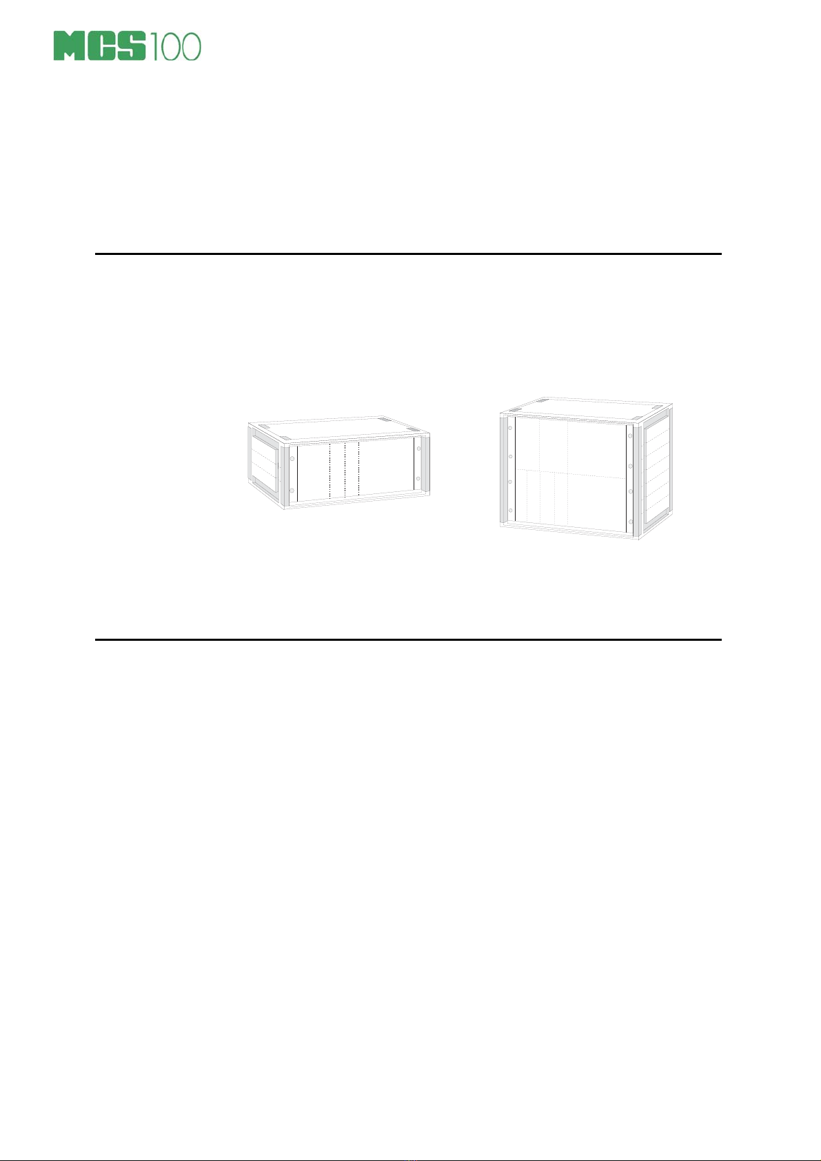
The base unit of the MCS100 Desktop System contains the cabinet
with a 19” frame for the modules, mains power supply, instrument air
supply and necessary connectors on the rear panel.
In the base unit virtually any
combination of the host modules and
assisting modules can be installed.
The base units come in two heights: BU4 and BU8.
Environmental Specification
Operating temperature 0°C to +40°C (32°F to 104°F)
Storage temperature -20°C to +60°C ( -4°F to 140°F)
Pressure media Clean, dry and oil free instrument air
Conforms to the EMC directive 89/336/EEC and the Low Voltage
Directive 72/23/EEC as attested by conformity with the following
harmonized standards:
Product Standard EN 61326
Safety Requirements EN 61010-1

MCS100 User Guide 7
Taking the Desktop System in use
Connect the mains to the MCS100. Switch on the MC5P host
module and check if it goes through its self test successfully. Switch
on possible other modules with a mains switch.
If any problems appear during the startup, please contact the
manufacturer or your local representative
Connect the pressure supply to the rear of the station. Pressure
supply is required for pressure output modules. Please observe the
following requirements before connecting the pressure supplies.
Instrument air supply
The calibration station requires clean, dry and oil free instrument air
supply. Filtering of the pressure supply is included in the base unit.
Maximum allowed supply air pressure is 10 bar gauge (145 psi).
The filter may be located according to user’s needs, but it needs to
be part of the pressure supply system at all times.
To minimize the danger of flying fragments in the event of a plastic
bowl failure, DO NOT REMOVE THE METAL BOWL GUARD of
the supply air filter. Certain compressor oils, chemicals, solvents,
paints and fumes can cause plastic bowl failure. Depressurize the
unit before removing the metal guard and bowl for service.
High pressure supply
For high pressure output modules there’s a separate supply input
connection. The maximum supply pressure is stated on the back
panel of the MCS100. For the PO20 pressure output module the
maximum supply pressure is 230 bar (3500 psi). For the pressure
output modules PO60, PO160 and PO250 the maximum supply
pressure is 400 bar (6000 psi).
High pressure is always dangerous! Read carefully the
warnings presented in Part C of this manual.
MCS100 User Guide 8
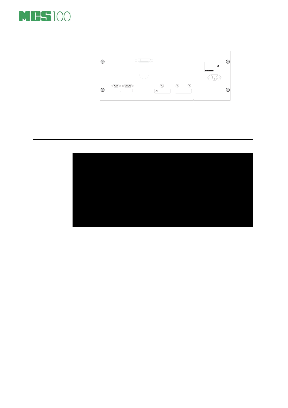
The rear panel of the MCS100 Desktop System.
H I G H P R E S S U R E S U P P L Y
M A X 2 3 0 b a r / 3 5 0 0 p s i
T y p e n r : 1 6 0 1
2 3 0 V ~ 5 0 H z
1 6 0 V A M A X
F u s e 2 * T 1 6 0 m A 2 5 0 V
V e r s i o n : A
M a d e i n F i n l a n d
C o m p / P r t E X T
7 b a r ( 1 0 b a r m a x . )
1 0 0 p s i ( 1 5 0 p s i m a x . )
f r o m d r y o i l f r e e
i n s t r u m e n t a i r s u p p l y
V A C U U M
S U P P L Y
The high pressure warning sign is on view only if a high pressure
output module is included in the Calibration Station. The max.
pressure supply values depend on the range of the pressure output
module.
Uninstalling and Installing Modules in the Desktop System
Warning!
Disconnect the mains cable and the pressure supply to your
MCS100 before you install or uninstall any modules.
The module uninstallation/installation must be carried out by
personnel qualified for electrical and pneumatic installations.
Refer to chapter Safety on page 4 for more specific information
on precautions during installation and uninstallation of
modules.
Before you uninstall any modules from the MCS100, the following
preoperations should be done:
Disconnect the mains supply from the MCS100.
Disconnect the supply pressure from the MCS100.
Disconnect the vacuum supply (if in use) from the MCS100.
Dismount the rear panel plate of the MCS100 chassis by opening
the four screws.
If your Desktop System is a BU8 Base Unit (it has modules
stacked on each other), the rear panel consists of two metal
plates, each fastened with four screws. In that case, dismount all
of the plates.
To uninstall a module
Disconnect all the cables and tubes connected from the module
to be uninstalled to the rear panel. Refer to the picture of internal
connections below.
Open the screws in the front plate of the module to be uninstalled
(four or more screws, depending on the module).
Pull out the module.
Installing a module requires opposite steps.
MCS100 User Guide 9
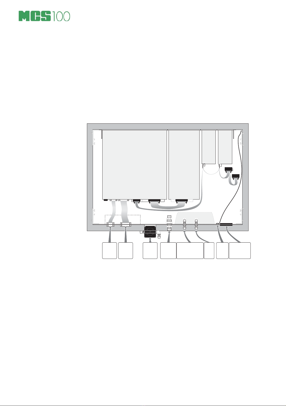
Internal connections
As the internal connections inside an MCS100 Desktop System
depend on the modules installed, it isn’t possible to present all the
combinations. The following picture is an example of internal
connections with an MC5P host module, and ET Module and two
pressure measurement modules. For readability reasons, the
internal pressure supply connections as well as the internal power
supply connections are not shown. Another picture of internal
connections is on page 21 in chapter Uninstalling and installing
modules in the Bench System.
1 0 p i n l a t t a 2 0 p i n l a t t a
9 p i n 1 5 p i n 2 0 p i n l a t t a
R e a r p a n e l
F r o n t p a n e l
M C 5 P
H o s t M o d u l e
P r e s s u r e
m e a s u r e -
m e n t
m o d u l e 1
P o w e r
C o m p / P r t A U X
P r e s s u r e
m e a s u r e -
m e n t
m o d u l e 2
M C 5 P
E T M o d u l e
P r e s s u r e
m e a s u r e m e n t
m o d u l e
d a t a l i n k
E T m o d u l e
d a t a l i n k
S o c k e t o u t p u t s f o r m o d u l e s
r e q u r n g 2 3 0 V / 1 1 5 V s u p p l y
S u p p l y p r e s s u r e
7 b a r ( 1 0 b a r m a x . )
1 0 0 p s i ( 1 5 0 p s i m a x . )
f r o m d r y o i l f r e e
i n s t r u m e n t a i r s u p p l y
H i g h
Pr e s s u r e
S u p p l y
M a x 2 0 0 b a r
3 5 0 0 p s i
V a c u u m
S u p p l y
E l e c t r i c a l
s u p p l y
c o n n e c t i o n
1 0 0 . . . 2 4 0 V A C
C o m p / P r t
( D a t a I / O )
A U X
( O p t i o n s
c o n n e c t o r )
I n s t r u m e n t
a i r f i l t e r
( d e f a u l t
l o c a t i o n )
E a r t h i n g

MCS100 User Guide 10
MCS100 Bench System
General
The MCS100 Bench System comes in two models, a High
workstation and a Low workstation. Each workstation comprises
three parts
module rack,
table frame and
table top.
Environmental Specification
Operating temperature 0°C to +40°C (32°F to 104°F)
Storage temperature -20°C to +60°C (-4°F to 140°F)
Protection To IP20
Pressure media Clean, dry and oil free instrument air
Conforms to the EMC directive 89/336/EEC and the Low Voltage
Directive 72/23/EEC as attested by conformity with the following
harmonized standards:
Product Standard EN 61326
Safety Requirements EN 61010-1
High Workstation
In the High Workstation the
module rack is raised above
the table top with a pair of
brackets.
The available widths of the
workstations are:
2030 mm approx. 6 ft 8”
1836 mm approx. 6 ft
1530 mm approx. 5 ft ¼”

MCS100 User Guide 11
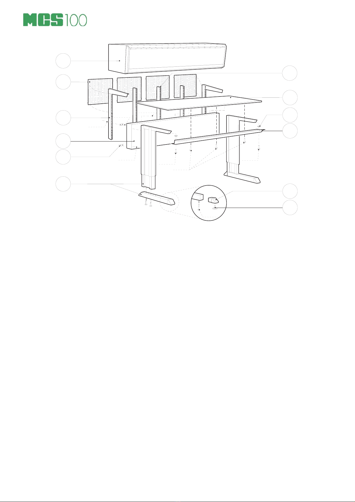
Assembly Instructions for High Workstations
Part List
Amount and part name
CODE
(if applicable)
Code in
the next
picture
1 Module rack with the modules installed A
3 Perforated plates 468 x 400 mm for a 1,5 m table or
3 Perforated plates 468 x 400 mm for a 1,8 m table or
4 Perforated plates 468 x 400 mm for a 2,0 m table
860800 B
2 Perforated plates 150 x 400 mm for a 1,8 m table 813486
1 pair of Brackets.
Inside each bracket are two M870 socket head
screws, M8 nuts and M8 washers. They are for
fastening the bracket.
For connecting the bracket to the bracket of another
table: two M612 crosshead screws, M6 nuts and
four M6 washers.
860288 C
1 Rear case, including the
Front list and the following utilities:
10 M816 socket head screws for fastening the
back case and the front list
6 M612 crosshead screws for fastening the
table top (not applicable for the corner unit)
6 M612 wood screws for alternate/additional
fastening of the table top
4 fitting parts with two M8 internal threads
each
2 flat nuts with an M8 internal thread
860019 D
J
E
I
1 Pair of legs, including the
leg caps and the
adjusting screws
860014 F
K
L
2 Perforated uprights for a 1,5 m table or
4 Perforated uprights for a 1,8 m table or
3 Perforated uprights for a 2,0 m table
Inside each perforated upright are two M870 socket
head screws and M8 nuts.
860142 G
1 Table top 860033 H
MCS100 User Guide 12
M × 1 6
D
E
M 6 ×1 2
M × 1 6 M × 1 6
L
J
H
G
M 6 × 1 2
A
B
CI
K
F
M × 7 0
M × 1 6
M × 1 6
1. Fix the adjusting screws Lto leg caps
K.
2. Fix the leg caps Kto the horizontal
part of the legs F. Fix the horizontal
part of the legs to the vertical parts (if
they are shipped separately).
3. Fix the rear case Dto the legs F,
smooth surface inside and with the
fixing holes for the table top up. Use
four M8×16 socket head screws.
4. Fix the flat nuts Ito the front list Jwith
M816 socket head screws (do not
tighten!). Push the front list Jin place
and tighten the screws.
5. Attach the fitting parts Eto the back
case Dwith four M816 socket head
screws (do not tighten!). Fix the
brackets C(2 pcs) with M870 socket
head screws to the rear case Dusing
the fitting part E(see picture on next
page).
6. Fix the perforated uprights G(the
amount of perforated uprights depends
on the width of your table, see picture
on next page) with M870 socket head
screws and M8 nut to the rear case E.
7. Fix the table top Hto the frame with six
M612 screws. If the table is equipped
with a drawer unit, the drawer fixing set
must be assembled before fixing the table
top. Note! The drawer unit includes it’s
own assembly instructions.
8. Install the isolation parts in the brackets
(see picture on next page).
9. Lift the module rack Aon to the brackets
Cand fasten it with the screws provided.
10.Fix the perforated plates Bto (the amount
of perforated plates depends on the width
of your table) to the perforated uprights
between the table top Hand the module
rack A.
Note that the frame of the table must
always be isolated from the module rack!
The height of the table top can be adjusted
between 670 to 1120 mm (approx. 26½” to
44”).
Max. loading capacity of the pair of brackets
Dis 120 kg (264 lbs).

MCS100 User Guide 13
Fixing the brackets to the rear case using
the fitting part:
Assembly instructions of the isolating
parts:
B r a c k e t
F i t t i n g
P a r t
M * 7 0
s o c k e t h e a d s c r e
w
W a s h e r , Ø 9
M * 1 6
s o c k e t h e a d s c r e w
R e a r C a s e
M 6 * 3 0
W a s h e r , Ø 7
( )
«
() Note! The isolating parts must
always be assembled as shown in
the picture.
The fixing points of the perforated uprights for the module rack and for the perforated
plates:
T a b l e T o p
2 m ´ 0 . 9 m
T a b l e T o p
1 . m ´ 0 . 9 m
T a b l e T o p
1 . 5 m ´ 0 . 9 m
5 0 c m 5 0 c m
5 0 c m4 0 c m5 0 c m5 0 c m5 0 c m 5 0 c m 4 0 c m 5 0 c m 5 0 c m
Corner Unit
The Corner Unit differs from a High
Workstation only by its special
look. Two High Workstations in a
90 degree angle may be combined
with the help of the Corner Unit.

MCS100 User Guide 14
How to Assemble the Corner Unit
We recommend that you first assemble the workstation(s) that will be
placed adjacent to the before assembling the corner unit.
1. Fix the front list Ato
the legs B. Use
M8×16 hexagon
socket head screws
and flat nuts.
2. Fix end plates Cto
the rear case D.
A
B
M × 1 6
Use M8×20 hexagon bolts and washers.
Note.
See the picture below for the purpose of each hole on the end
plate. Also remember to position the rear case so that the
fastening holes for the table top are on the upper side.
E
D
M × 1 6
2 × M × 2 0
P e r f o r a t e d U p r i g h t
R e a r C a s e
Leg
B r a k e t
C
3. Fix the rear case Dwith end plates to the legs E. Use M8×16
hexagon bolts and washers.
4. Fix the brackets Fto
the end plate Cusing
M8×70 hexagon
bolts, washers and
M8 nuts. Do not
tighten yet.
5. Fix the perforated
uprights Gto the end
plate Cusing M8×70
hexagon bolts,
washers and M8
nuts. Do not tighten
yet.
F
G
M
M × 7 0
Table of contents
Other BEAMEX Test Equipment manuals


