HWH 100 Series User manual

OPERATOR’S MANUAL
ML10035/MP05.0500/LH-S
26FEB04
Four Lever Control
Hydraulic Leveling
FEATURING:
HWH CORPORATION
(On I-80, Exit 267 South)
2096 Moscow Road | Moscow, Iowa 52760
Ph: 800/321-3494 (or) 563/724-3396 | Fax: 563/724-3408
www.hwh.com
100 SERIES LEVELING SYSTEM
HWH LEVER-CONTROLLED
Straight-Acting Jacks
AP10035
W
CORPORATION
HH
R
BEFORE USING. BLOCK FRAME AND TIRES SECURELY
LR
BEFORE REMOVING TIRES OR CRAWLING UNDER VEHICLE.
STORE
EXTEND
LF RF
CORPORATION
HWH
R
RR
CAUTION! UNDERSTAND OPERATOR’S MANUAL
RR
RR
LEVELING
UNDERSTAND OPERATOR’S MANUAL BEFORE USING.
REMOVING TIRES OR CRAWLING UNDER VEHICLE.
BLOCK FRAME AND TIRES SECURELY BEFORE
CAUTION!
HYDRAULIC
5AMP
FUSE
LR
LR
WARNING
H
CORPORATION
LF
H
LF
W
LEVEL
RF
R
RF
OFF
LEVEL
SEPARATE CONTROLS
R

CAUTION !
READ THE ENTIRE OPERATOR’S MANUAL BEFORE OPERATING.
MOVE FORWARD OR BACKWARD WITHOUT WARNING CAUSING INJURY OR DEATH.
EXTENSION.
CAUSING INJURY OR DEATH.
CHIPS, OIL LEAKS, ETC. FOLLOW ALL OTHER APPLICABLE SHOP SAFETY PRACTICES.
NOTE: KEEP THE CONTROL VALVE LEVERS IN THE STORE POSITION WHEN JACKS ARE NOT IN USE.
OPERATOR’S MANUAL
BLOCK FRAME AND TIRES SECURELY BEFORE CRAWLING UNDER VEHICLE. DO NOT USE LEVELING JACKS OR AIR
SUSPENSION TO SUPPORT VEHICLE WHILE UNDER VEHICLE OR CHANGING TIRES. VEHICLE MAY DROP AND/OR
THE JACKS MAY ABRUPTLY SWING UP WHEN THE FOOT CLEARS THE GROUND OR WHEN JACK REACHES FULL
NEVER PLACE HANDS OR OTHER PARTS OF THE BODY NEAR HYDRAULIC LEAKS. OIL MAY PENETRATE SKIN
WEAR SAFETY GLASSES WHEN INSPECTING OR SERVICING THE SYSTEM TO PROTECT EYES FROM DIRT, METAL
IMPORTANT: IF VEHICLE IS EQUIPPED WITH A ROOM EXTENSION, READ ROOM EXTENSION SECTION BEFORE
OPERATING LEVELING SYSTEM.
IF THIS VEHICLE IS EQUIPPED WITH KICK-DOWN STYLE JACKS, DO NOT OVER EXTEND THE REAR JACKS. IF
THE WEIGHT OF THE VEHICLE IS REMOVED FROM ONE OR BOTH REAR WHEELS, THE VEHICLE MAY ROLL FOR-
WARD OR BACKWARD OFF THE JACKS.
MP15
30MAY01
KEEP ALL PEOPLE CLEAR OF VEHICLE WHILE LEVELING SYSTEM AND ROOM EXTENSION ARE BEING OPERATED.
problem, please do the following:
customer satisfaction. Therefore, if you discover a defect or
HWH CORPORATION strives to maintain the highest level of
THIS IS NOT TO BE INTERPRETED AS A STATEMENT OF WARRANTY
HOW TO OBTAIN WARRANTY SERVICE
(563) 724-3396 OR (800) 321-3494. Give your name and
address, coach manufacturer and model year, date the
HWH CORPORATION 2096 Moscow Rd. Moscow IA. 52760
notify the Customer Service Department:
If your dealer cannot or will not solve the problem,
Service Department, at HWH CORPORATION.
the problem, he should immediately contact the Customer
the problem quickly. If the dealer has difficulty solving
management people are in the best position to resolve
vehicle or had the leveling system installed. Dealership
Notify the dealership where you purchased the
SECOND:
FIRST:
authorized by HWH CORPORATION, or at the
must be performed by an independent service facility
determined by HWH CORPORATION. All warranty repairs
authorization of an independent service facility, to be
defective part, either by appointment at the factory or by the
CORPORATION will authorize repair or replacement of the
determine whether or not your claim is valid. If it is, HWH
HWH CORPORATION personnel will contact you to
during business hours (8:00 a.m. till 5:00 p.m. c.s.t.).
description of the problem, and where you can be reached
coach was purchased, or the date of system installation,
HWH CORPORATION factory, unless prior written approval
has been obtained from proper HWH CORPORATION
personnel.

CONTROL FUNCTIONS
A red "WARNING" light will be on when-
CONTROL IDENTIFICATION
MP25.0505
30JAN97
CONTROL BUTTONS INDICATOR LIGHTS
This switch controls power
to the "LEVEL" and "WARNING" lights, and the power unit. It
does not control power to the master "JACKS DOWN" warning
light, the master WARNING light on the panel, or the buzzer.
A lit yellow "LEVEL" light indicates the
corresponding corner is low. Extend the appropriate jack(s) to
put out the yellow light(s). One or two yellow lights can be on
at the same time. The coach is level when all yellow lights
are out.
This fuse protects the panel.
"LEVEL/OFF" ROCKER SWITCH:
CONTROL CIRCUIT FUSE:
JACK CONTROL LEVER:
WARNING BUZZER:
"LEVEL" LIGHTS:
"WARNING" LIGHTS:
ON/MASTER WARNING LIGHT:
BEFORE USING. BLOCK FRAME AND TIRES SECURELY
BEFORE REMOVING TIRES OR CRAWLING UNDER VEHICLE.
UNDERSTAND OPERATOR’S MANUAL
CAUTION!
H
CORPORATION
H
W
R
EXTEND
STORE
LR LF RF RR
H
CORPORATION
H
W
R
LEVEL
HYDRAULIC LEVELING
WARNING
CAUTION!
BLOCK FRAME AND TIRES SECURELY BEFORE
REMOVING TIRES OR CRAWLING UNDER VEHICLE.
LEVEL
OFF
FUSE
5AMP
LR
LR LF
LF RF
RF
RR
RR
UNDERSTAND OPERATOR’S MANUAL BEFORE USING.
"WARNING" LIGHTS
(4 - Red)
CONTROL CIRCUIT
FUSE
"LEVEL" LIGHTS
(4 - Yellow)
ON/MASTER
WARNING LIGHT
"LEVEL/OFF"
ROCKER SWITCH
JACK CONTROL LEVER
(4)
(5 Amp)
This light will be on if the
ignition is the "ON" or "ACC" position and the "LEVEL/OFF"
rocker switch is in the "LEVEL" position or if any one of the jacks
are extended 2 inches or more and the ignition switch is in
the "ON" or "ACC" position.
provided the ignition switch is in the "ACC" or "ON" position
and the system is on. Some coaches are equipped with a
dash mounted master "JACKS DOWN" light which will be on
when one or more jacks are extended 2 inches or more, pro-
ever the corresponding jack is extended 2 inches or more,
vided the ignition switch is in the "ON" position.
tended 2 inches or more and the ignition switch is in the "ON"
position.
These levers control individual
jacks. Push a lever toward "EXTEND" to extend a jack or
"STORE" to retract a jack.
A buzzer will sound if any jack is ex-

OPERATION PROCEDURES
LEVELING PROCEDURE
1. Place gear selector in the park position apply the park brake.
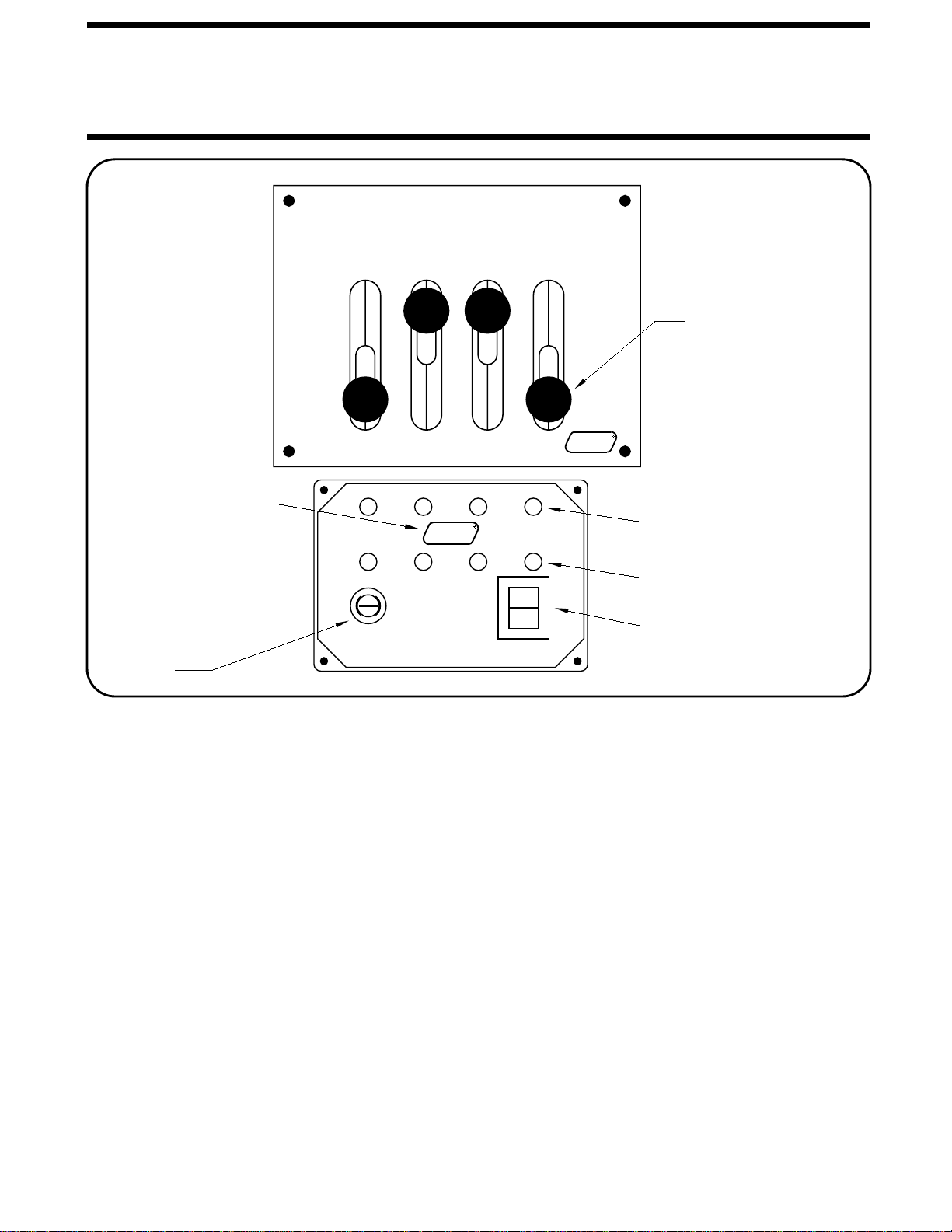
3. Push the rocker switch in jack control plate to "LEVEL".
6. Turn off the rocker switch on the leveling system panel.
7. Turn off the ignition switch.
SITE SELECTION
MP35.1032
19NOV07
If the ground is too uneven the jacks may not have enough
stroke to level the vehicle. The vehicle may have to be moved.
ROOM EXTENSION PROCEDURES
extension read this section carefully.
If the vehicle is equipped with kick-down jacks, the wheels MUST
be blocked securely. Do NOT operate any room extension
until the leveling and stabilizing procedure is complete. Do
IMPORTANT: If the vehicle is equipped with a room
NOT retract the leveling system until all room extensions are
retracted. NEVER operate the leveling system when any
Refer to the vehicle owner’s manual for proper operation of
room extensions are extended.
room extensions.
IMPORTANT: Do not use a room extension support
when the vehicle is supported by the leveling system.
Block tires securely.
2. Turn the ignition switch to "ACCESSORY".
Park with the front of the vehicle facing downhill if possible.
inches. Alternate between the rear and front jacks until the
inches. Then extend the front jack to lift the vehicle 1 or 2
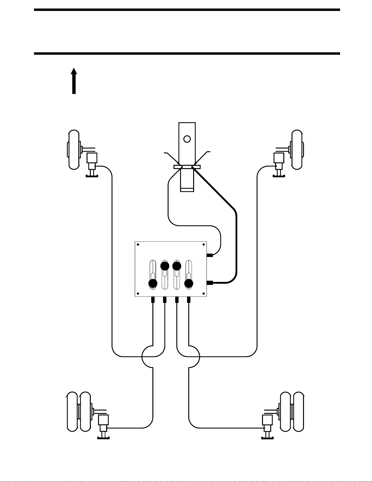
the rear jack. Extend the rear jack to lift the vehicle 1 or 2
left front and left rear or right front and right rear, start with
operating a second jack. If both side yellow lights are on,
do not lift the vehicle more than 1 or 2 inches without
If leveling is accomplished by operating one jack at a time,
the vehicle is level.
yellow lights are on. When all four yellow lights are out,
rear yellow "LEVEL" light is on, operate the right front and
of the yellow lights. As a jack extends two inches or more,
"EXTEND" for an extended period of time.
will result if control levers are partially operated toward
IMPORTANT: Overheating and excessive current draw
right rear jacks together. Do the same if both front or rear
vehicle and jacks. If for example, a right front and a right
often provides a smoother lift while reducing stress on the
time, if desired. Operation of both jacks at the same time
LEVELING TIPS: Two jacks maybe operated at the same
the vehicle is low. Extend jacks as needed to put out all
4. Lit yellow "LEVEL" lights indicate that a side or end of
front (or rear) yellow light are on, extend the jack that is not
provides additional stability against wind and activity in the
stabilize the vehicle should lift the vehicle at least 3/4". This
may be extended until they touch the ground. Jacks used to
5. After the vehicle is level, the jacks not used for leveling
go out. When all four yellow lights are out the vehicle is level.
between the two front (or rear) jacks until both yellow lights
on the ground until it lifts the vehicle slightly. Then alternate
vehicle.
If a front (or rear) jack is extended to the ground and the two
Repeat this with the two front or two rear jacks as necessary.
two side yellow lights go out.
If parking on soft ground or asphalt paving, wood blocks or pads should be placed under the jacks.
its respective red "WARNING" light will come on.

OPERATING PROCEDURES
CAUTION:DO NOT MOVE THE VEHICLE WHILE
THE LEVELING JACKS ARE STILL IN CONTACT WITH
THE GROUND OR IN THE EXTEND POSITION. THIS
VEHICLE IS EQUIPPED WITH STRAIGHT-ACTING JACKS
.
MOVING THE VEHICLE WITH THE LEVELING JACKS
EXTENDED CAN CAUSE SEVER DAMAGE TO THE JACKS
AND/OR THE VEHICLE AND CREATE A DRIVING HAZARD
.
DO NOT RELY SOLELY UPON WARNING LIGHTS. IT IS
RETRACT PROCEDURES
CAUTION:
MAKE SURE THAT PEOPLE AND EQUIP-
MENT ARE CLEAR OF THE VEHICLE.
THE OPERATOR’S RESPONSIBILITY TO CHECK THAT
ALL JACKS ARE FULLY RETRACTED INTO THE
JACK POSITIONS
2. Visually check that all jacks are in the STORE/TRAVEL
JACKS IN THE STORE/TRAVEL POSITION.
IN THE "STORE" POSITION WHILE TRAVELING TO KEEP THE
THE CONTROL LEVERS SHOULD BE KEPT
CAUTION:
1. Move the control levers to the "STORE" position. Retracting
the two rear jacks followed by the two front jacks will provide
a smooth retraction.
3. Push the rocker switch on the jack control plate to "OFF".
Turn the ignition off or proceed to travel.
EXTEND POSITION STORE/TRAVEL POSITION
position. With the ignition switch in the "ON" position and the
rocker switch in the "LEVEL" position, the red WARNING light,
the master "JACKS DOWN" light and the buzzer will be off.
MP35.103
4
18JUL0
5
fail to retract completely, extend the jacks back down
to the ground then retract the jacks again.
NOTE: If the vehicle is parked or stored with the jacks
extended for an extended period of time and the jacks
STORE/TRAVEL POSITION.

MP45.0
3
13NOV1
7
MAINTENANCE
LEVEL SENSING UNIT ADJUSTMENT
UNUSUAL CONDITIONS
BELOW THE SURFACE MOUNTING
LEVEL SENSING UNIT
ON TOP
STICKER SCREWS (3)
UP
SIDE
THIS
REAR
SPRINGS (3)
MOUNTING
SURFACE
OIL LEVEL
ELECTRICAL SYSTEM
The batteries should be in good condition and fully charged.
All electrical connections, especially ground connections,
should be clean, tight, free from corrosion and protected
from corrosion. Weak batteries can cause erratic operation.
Battery cable terminals, battery posts and connections
should be kept clean and protected from corrosion.
NOTE: All major components of the system can be replaced
with rebuilt parts or can be sent to HWH CORPORATION to
be rebuilt, when the system is out of warranty.
In west or icy weather leveling jacks may become encrusted
with ice. This may cause the leveling system to function
improperly. To eliminate this problem, periodically check the
leveling jacks and break loose any ice which may be
causing improper operation.
If driving conditions are unusually muddy, the jacks may
become caked or clogged with mud. This condition may
hamper the proper operation of the leveling system. This
problem may be prevented or remedied by cleaning off each
leveling jack if they become excessively muddy.
Do not move the vehicle while the leveling jacks are still in
contact with the ground. Place the system in the store mode
and then visually check to see if the leveling jacks have
returned to the STORE/TRAVEL position.
MOUNTING SURFACE
ELECTRONIC LEVEL SENSING UNIT
BELOW THE SURFACE MOUNTING
FRONT
SIDE
THIS
UP
SCREWS (3)
SPRINGS (3)
Level the vehicle by placing a circular bubble level in the center of the freezer floor or location within the vehicle that
is to be level. With the vehicle level, adjust the sensing unit until all yellow lights are off. This is done by drawing up
the corresponding screw if the sensing unit is mounted below the surface as shown or backing out the corresponding
screw if the sensing unit is mounted above the surface. Bump the sensing unit to see that it is settled tight against all
three screw heads and still indicates that the unit is level.
and steps should be fully retracted before checking fluid
level. The oil reservoir is part of the pump / manifold
assembly. The oil level is checked and filled through the
breather cap. Clear any dirt away from the breather / filler
cap before removing.
Any HWH hydraulic equipment, including jacks, slide-outs
servicing of the coach.
All maintenance should be done as part of the normal
there is an oil leak in the system.
purchased and then once every two years. More often if
The oil level should be checked when the vehicle is first
brake fluid or hydraulic jack fluid. Use of these can damage
and can cause staining should a leak occur. DO NOT USE
HWH Specialty Hydraulic Oil is recommended. In an
Dexron automatic transmission fluid contains red dye
emergency Dexron automatic transmission fluid can be used
.
NOTE: Overfilling the tank can cause leakage of oil
should be between the bottom of the dipstick and the
reservoir. Most breather caps have a dipstick. Fluid level
The oil level should be within one inch of the top of the
through the breather cap.
center mark.
FLUID:
seals.
NOTE:

MAINTENANCE
HYDRAULIC CONTROL VALVE ADJUSTMENT
Two parts of the control valve are possible to adjust. The proper
adjustments for these parts are made at the factory, so readjust-
ments will rarely be necessary.
under warranty, the complete valve unit should be replaced,
but not the light panel.
The following procedures are recommended to adjust them if
the need arises.
1. ADJUSTMENT OF THE DETENT PLATE: Adjustment of
the detent plate is necessary if the detent plate fails to hold
the control levers in the retract position, or if the plunger is not
depressed sufficiently by the valve handle in the retract position.
To adjust the detent plate, loosen the nuts which hold the valve
mounting brackets and the detent plate to the valve assembly
The proper adjustment can be made by moving the detent plate
up or down to a point where the valve handle is resting solidly
on the detent in the retract position, yet holding the plunger
down to it’s full extent or no less than 1/16" of this extension.
2. ADJUSTING THE MICRO SWITCH: The micro switch will
need adjusting if the activating rod does not fall directly upon
the nipple of the micro switch.
The adjustment must be made after disassembling a portion of
of the control valve. First, remove the mounting bracket and
the detent plate. Next, remove the snap rings on the pivot rod,
and carefully slide off the valve handles spacers and spring,
notice where each part must go during reassembly.
The micro switch is the adjusted by loosening the small hex nuts
which hold the micro switch to the pivot plate, and then making
Finally, reassemble the control valve, remembering to properly
adjusting the detent plate as it is replaced.
PLUNGER
ROD
PIVOT ROD
SNAP RING
VALVE ASSEMBLY
SPACER
SPACER
SPRING
SPACER
PIVOT ROD
MOUNTING
BRACKET
NUTS
VALVE
HANDLE
PIVOT
PLATE
MICRO
SWITCH
ACTIVATING
ROD
MOUNTING
BRACKET
DETENT
PLATE
the microswitch correctly.
the proper adjustment.
NOTE:
These valve adjustments should only be made on a
non-warranty basis. If the valve needs to be repaired or adjusted
NOTE:
Sometimes the activating rod can be bent to position
4 LEVER HYDRAULIC CONTROL VALVE
01MAY97
MP45.3

MP55.9
07NOV97
vehicle’s suspension and electrical system, as well as an understanding of the leveling system’s hydraulics and electronics
is required.
1. JACK RETRACTS AFTER COACH IS LEVEL.
A. Hose or jack has external leak.
B. Fluid is leaking back to reservoir through control valve.
2. LEVELING JACKS WILL NOT RETRACT COMPLETELY.
A. Jack clogged with mud or ice.
B. Main rod bent or scored.
C. Valve plunger not completely depressed by valve handle.
D. Springs weak or broken.
E. Hydraulic line pinched.
3. IGNITION SWITCH ON, BUT NO POWER TO PUMP AND/
OR LIGHT.
A. Bad micro switch.
B. Pump relay not functioning.
D. Bad rocker switch.
C. 12 volts from main power source not present.
G. Blown fuse.
E. Faulty wire or electrical connection.
F. Pump not grounded.
4. LEVELING LIGHTS (YELLOW) NOT FUNCTIONING
PROPERLY.
5. WARNING LIGHTS (RED) NOT FUNCTIONING PROPERLY.
A. Light will not come on: check for broken wire at warning
switch on the jack.
B. Lights will not go out: bad warning switch or wires are shorted
7. HYDRAULIC PUMP ACTIVATES WITHOUT USE OF
C. Pump is not developing pressure.
CONTROL VALVE HANDLES.
B. Oil supply low in reservoir.
D. Broken hydraulic line.
6. HYDRAULIC PUMP ACTIVATES, BUT THE JACKS WILL
NOT EXTEND.
A. Micro switch out of adjustment.
D. Short in PC board.
D. Broken spring on pivot rod.
The following is a list of troubles, and possible solutions which might occur to the leveling system.
C. Pump relay stuck.
A. Control valve not in the full "EXTEND" position.
A. Yellow lights will not go out when vehicle is level: adjust
sensing unit.
B. More than two yellow lights on: replace sensing unit.
C. Check PC board.
C. Check PC board.
to ground.
TROUBLE SHOOTING
LEVELING SYSTEM
NOTE:
Only qualified technicians should install or repair leveling systems on vehicles. A knowledge of hydraulics, welding, the

LF RF
RR
FRONT
RETURN
PRESSURE
100 SYSTEM
HYDRAULIC LINE CONNECTION DIAGRAM
MP65.0505
24AUG95
LR
EXTEND
STORE
FOUR LEVER SEPARATE CONTROL

100 SERIES LEVER-CONTROLLED LEVELING SYSTEM
WITH 4 LEVERS AND SEPARATE CONTROLS
SEE PANEL
CONNECTION
DIAGRAM
SENSING
UNIT
MASTER WARNING
LIGHT/BUZZER
CONNECTION DIAGRAM
PACKARD CONNECTORS
COLORS TO A & B ON
DO NOT REVERSE WIRE
A
B
LF
(WHITE) 6230
A
LR (GREEN)
B
(WHITE)
RR
(BLACK)
(WHITE)
A
B
(WHITE)
RF
2000
FROM +12 ACC FUSE
15 AMP MAX -
TO WARNING
SWITCH TO WARNING
SWITCH
WARNING
SWITCH
WARNING
SWITCH MP85.0505
18JAN99
A
B
(RED) 6120
SEE PUMP RELAY
ELECTRICAL
CONNECTION DIAGRAM
BEFORE USING. BLOCK FRAME AND TIRES SECURELY
BEFORE REMOVING TIRES OR CRAWLING UNDER VEHICLE.
UNDERSTAND OPERATOR’S MANUAL
CAUTION!
H
CORPORATION
H
W
R
EXTEND
STORE
LR LF RF RR
H
CORPORATION
H
W
R
LEVEL
HYDRAULIC LEVELING
WARNING
CAUTION!
BLOCK FRAME AND TIRES SECURELY BEFORE
REMOVING TIRES OR CRAWLING UNDER VEHICLE.
LEVEL
OFF
FUSE
5AMP
LR
LR LF
LF RF
RF
RR
RR
UNDERSTAND OPERATOR’S MANUAL BEFORE USING.
ELECTRICAL CONNECTION DIAGRAM
(GRAY)
6230
(ORANGE)
1000
NOTE: THE (4) DIGIT WIRE NUMBER
SUPERSEDES ANY AND ALL
WIRE COLORS
6230
4000 6230
3000

2-PIN MTA
VALVE MICRO SWITCH
ELECTRICAL CONNECTION DIAGRAM
WITH 4 LEVERS AND SEPARATE CONTROLS
NOT USED
RR - (BLACK) 3000
RF - (GRAY) 2000
LF - (ORANGE) 1000
LR - (GREEN) 4000
+WARN - (PURPLE) 6121
-WARN - (BROWN) 7699
PUMP - (BLUE) 6820
GROUND - (WHITE) 6230
RR - RED
RF - GREEN
LF - BLACK
LR - YELLOW
COM. - WHITE
PUMP RELAY CONNECTION DIAGRAM
PANEL CONNECTION DIAGRAM
* FUSE MAY BE REQUIRED - CHECK APPLICABLE CODE
TO ACCESSORY +12 POWER
FUSED 15A MAX. - (RED) 6120
PUMP MUST BE MOUNTED SOLIDLY TO FRAME. SOME PUMPS HAVE A HARNESS -
WIRE FROM
BATTERY
GROUND
-
GROUND CABLE THAT IS TO BE ATTACHED TO THE GROUND STUD.
+
* FUSE
FUSED 10A -
FROM HARNESS
GROUND STUD
FROM RELAY TO
GROUND STUD -
IF THE PUMP BRACKET IS WELDED TO THE
FRAME, USE THE GROUND STUD TO ATTACH THE
PUMP TO THE BRACKET. IF THE PUMP BRACKET IS
BOLTED TO THE FRAME, USE THE GROUND STUD TO
ATTACH THE BRACKET TO THE FRAME.
100 SERIES LEVER-C0NTROLLED LEVELING SYSTEM
NOTE:
9-PIN MTA
HARNESS
5-PIN MTA
SENSING UNIT
(BLUE) 6820
(WHITE) 6231
(WHITE) 6230 NOTE: THE (4) DIGIT WIRE NUMBER
SUPERSEDES ANY AND ALL
WIRE COLORS
NOTE: THE (4) DIGIT WIRE NUMBER
SUPERSEDES ANY AND ALL
WIRE COLORS
MP85.0510
18JAN99

LIGHT PANEL (INTEGRATED OR REMOTE 4-LEVER) SYSTEM
INDICATOR LIGHTS
YELLOW LEVEL
HWH
LIGHT
LOGO
GROUND - (WHITE) 6230
(BLUE) 6820
(BROWN) 7699
MICRO SWITCH
PUMP
5 AMP.
LF - (ORANGE) 1000
RF - (GRAY) 2000
RR - (BLACK) 3000
LIGHTS
WARNING
RED
(RED) 6120
+12V ACCESSORY -
FUSE
M
4 LEVER VALVE
JACK
WARNING
SWITCHES
NOT USED
LR - (GREEN) 4000
ROCKER
SWITCH
PUMP
STRAIGHT-ACTING JACKS WITHOUT AIR DUMP FEATURE
ELECTRICAL SCHEMATIC
* BATTERY
BUZZER 5 AMP
FUSE
12V
IGN.
JACK
DOWN
LIGHT
+
-
RELAY 6231
6111 6111
100/110 SERIES LEVELING SYSTEM
NOTE: THE (4) DIGIT WIRE NUMBER
SUPERSEDES ANY AND ALL
WIRE COLORS
MP85.9935
26AUG05
ELECTRONIC LEVEL
SENSING UNIT
RR ORANGE
LF BLACK
RF GREEN
+12 RED
LR YELLOW
GND. WHITE
PC BOARD
LIGHT PANEL
CHECK APPLICABLE CODE.
* FUSE MAY BE REQUIRED

LINE FUSE HOLDER
JACKS DOWN LIGHT
INCLUDED IN
HARDWARE KIT.
CONNECT THIS END
TO IGNITION "ON" POWER.
5-15 AMP FUSE
+
_
PIGTAIL
W/ DIODE AND IN
BUZZER
MP85.9999
13JAN99
SEE PANEL
CONNECTION
DIAGRAM
CONNECTION
DIAGRAM
SEE PANEL
WARNING LIGHT WIRES ARE INCLUDED
IN 9 OR 11 PIN MTA PLUG
+
-
MASTER LIGHT/BUZZER CONNECTION DIAGRAM
MANUAL LEVELING SYSTEMS
A MASTER WARNING INDICATOR SHOULD ALWAYS BE USED. WHEN THE LEVELING SYSTEM HAS STRAIGHT-
ACTING JACKS A WARNING BUZZER MUST BE USED.
WHEN ONLY A RED MASTER WARNING LIGHT IS USED THE 12+ POWER FOR THE LIGHT COMES THROUGH THE
CONTROL PANEL. (SEE FIGURE 1 BELOW.) WHEN BOTH A RED LIGHT AND WARNING BUZZER ARE USED THE
+12 POWER FOR BOTH INDICATORS IS SUPPLIED BY THE IGNITION SWITCH. THE POWER MUST COME FROM
THE "ON" SIDE OF THE IGNITION SWITCH, NOT THE "ACC" SIDE. (SEE FIGURE 2 BELOW)
BY SUPPLYING IGNITION POWER TO THE WARNING BUZZER AND LIGHT, AND "ACC" POWER TO THE CONTROL
PANEL, THE SYSTEM MAY BE OPERATED IN ACCESSORY WITHOUT THE BUZZER SOUNDING. THE NEGATIVE SIGNAL
FOR THE WARNING INDICATORS MUST ALWAYS COME FROM THE CONTROL PANEL.
CAUTION:
THE PURPLE WIRE IN THE MASTER WARNING LIGHT HARNESS IS HOT WHENEVER THE IGNITION
IS "ON" OR IN "ACC". THE PURPLE WIRE MUST BE REMOVED FROM THE HARNESS WHEN USING DIRECT IGNITION
VOLTAGE FOR THE MASTER WARNING INDICATORS.
FIGURE 1
FIGURE 2
NOTE:
6111
NOTE: THE (4) DIGIT WIRE NUMBER SUPERSEDES ANY AND ALL WIRE COLORS.
CONTROL WIRE - (BROWN) 7699
PIGTAIL
PROVIDED - (BROWN) 7699
NOTE: DO NOT USE
(PURPLE) WIRE - 6121
REMOVE (PURPLE) WIRE - 6121
FROM HARNESS.
NOTE: SPLICE (BROWN) WIRE - 7699
FROM HWH LIGHT PLATE TO
(BROWN) - 7699 PIGTAIL
WITH BUTT CONNECTOR.
+12 - (PURPLE) 6121
Other manuals for 100 Series
2
Table of contents
Other HWH Jack manuals