OPERATING PROCEDURES
MP34.3303
18DEC09
MANUAL JACK RETRACTION
been opened far enough to allow the jacks to retract.
the T-Handle will turn harder. Make sure the valves have
will turn several turns easily. As the valve starts to open,
Large style with T-Handle valve release:
power unit. The upper most manifold should control
NOTE: Multiple manifolds may be present on the
retract the jacks.
if the STORE feature on the HWH control panel will not
Use the manual valve release for retracting the jacks only
DO NOT CRAWL UNDER THE VEHICLE, KEEP A SAFE
DISTANCE IN FRONT AND REAR OF THE VEHICLE.
THE VEHICLE MAY DROP AND/OR MOVE FORWARD
OR BACKWARD WITHOUT WARNING AS THE VALVE
RELEASE IS OPERATED.
1. Locate your power unit-manifold assembly.
2. Allow clearance for the vehicle to lower. If equipped with
CAUTION:KEEP AWAY FROM THE WHEELS,
point as internal damage may occur to the solenoid.
incorporated into the Breather Cap. Before using read
NOTE: As of APRIL 2002 a 1/4" Nut Driver has been
and understand the last page of this manual.
6. Check that all jacks are now retracted. If yes, continue.
7. Close the valves by turning each valve release clockwise.
DO NOT tighten the manual valve release past this
IMPORTANT: Once the manual valve release is snug,
9. The system should now be repaired before using again.
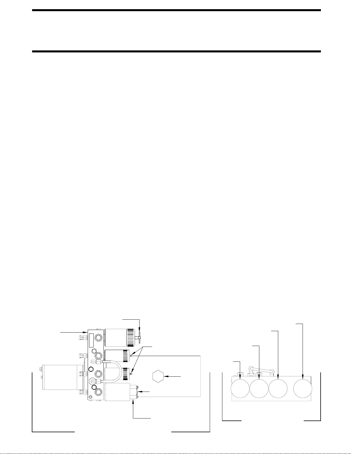
3. Using the diagrams below identify the style and location
5. Repeat the process by identifying then opening the two
rear control valves.
LARGE STYLE WITH T-HANDLE
VALVE RELEASE
SMALL STYLE
WITH VALVE
RELEASE NUT
LARGE STYLE
RELEASE NUT
WITH VALVE
PLASTIC PLUG
BREATHER
CAP
Small style with Valve Release Nut: DO NOT
1/4" valve release nut more than . Turning
the nut more could damage the valve.
The T-Handle
turn the
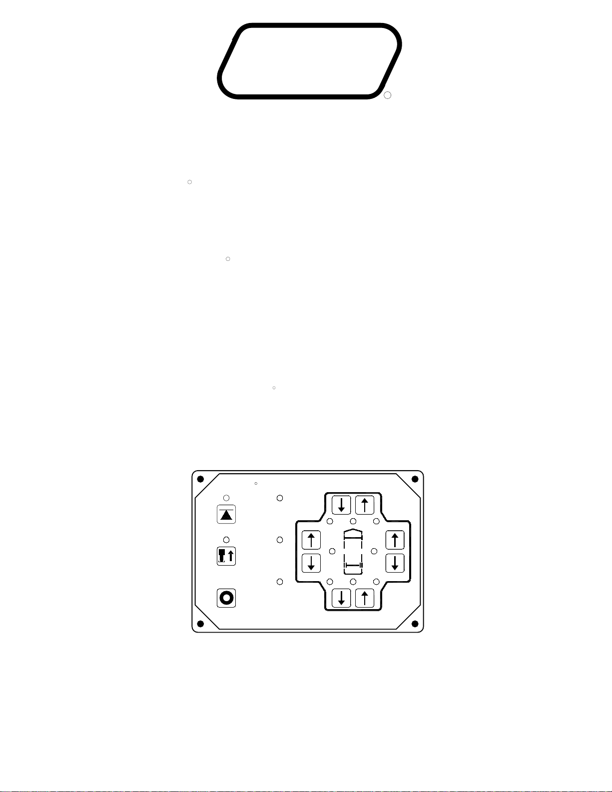
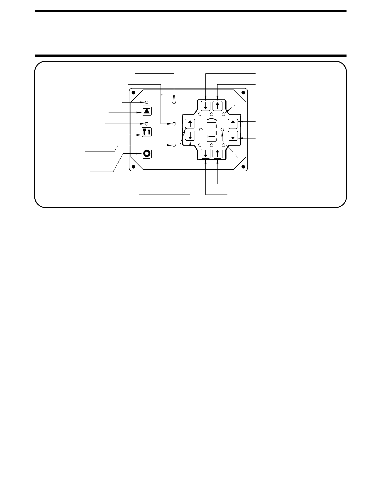
jack functions. (Valve styles and arrangements will vary)
POWER UNIT-MANIFOLD ASSEMBLY
MANIFOLD
of your two front jack control valves.
If no, notify the dealership where you purchased the vehicle
or had the leveling system installed or contact
(The diagram below represents a typical Power Unit-
MANUAL JACK RETRACTION
extensions are fully retracted prior to performing
IMPORTANT: HWH recommends that all HWH room
manual jack retraction procedures.
Manifold Assembly it may not be an exact match to yours).
4. Retract the front jacks by opening the correct valves.
Slowly turn the manual valve releases counter clockwise
until the jacks start to retract. Hitch the trailer to the tow
4 and 1/2 turns
HWH Corporation customer service.
FOR TRAILERS WITHOUT LOCK VALVE
RR RF LR
LF
VALVE ARRANGEMENT
TRAILER
RIGHT
REAR
FRONT
RIGHT
LEFT
FRONT REAR
LEFT
landing gear, lower the landing gear to support the trailer
while manually retracting the jacks.
vehicle during this operation if the vehicle is not equipped
8. Retract all landing gear before traveling.
with an alternate landing gear.
valve. Replace the protective plastic plug.
Turning the nut more could damage the
release nut more than
The 1/4" Valve
removed to gain access. Open valve 1-1/2 to 2 full turns.
release nut is located under a plastic plug that must be
turn the 1/4" valve
Large style with Valve Release Nut:
2 full turns.
DO NOT