OPERATING PROCEDURES
MP35.5109
28JUL98
AUTOMATIC HYDRAULIC LEVELING
CAUTION:
IMPORTANT:
1.Place transmission in the recommended position for parking
vehicle and set parking brake. Turn the coach engine off.
Turn the ignition to the "ACCESSORY" position.
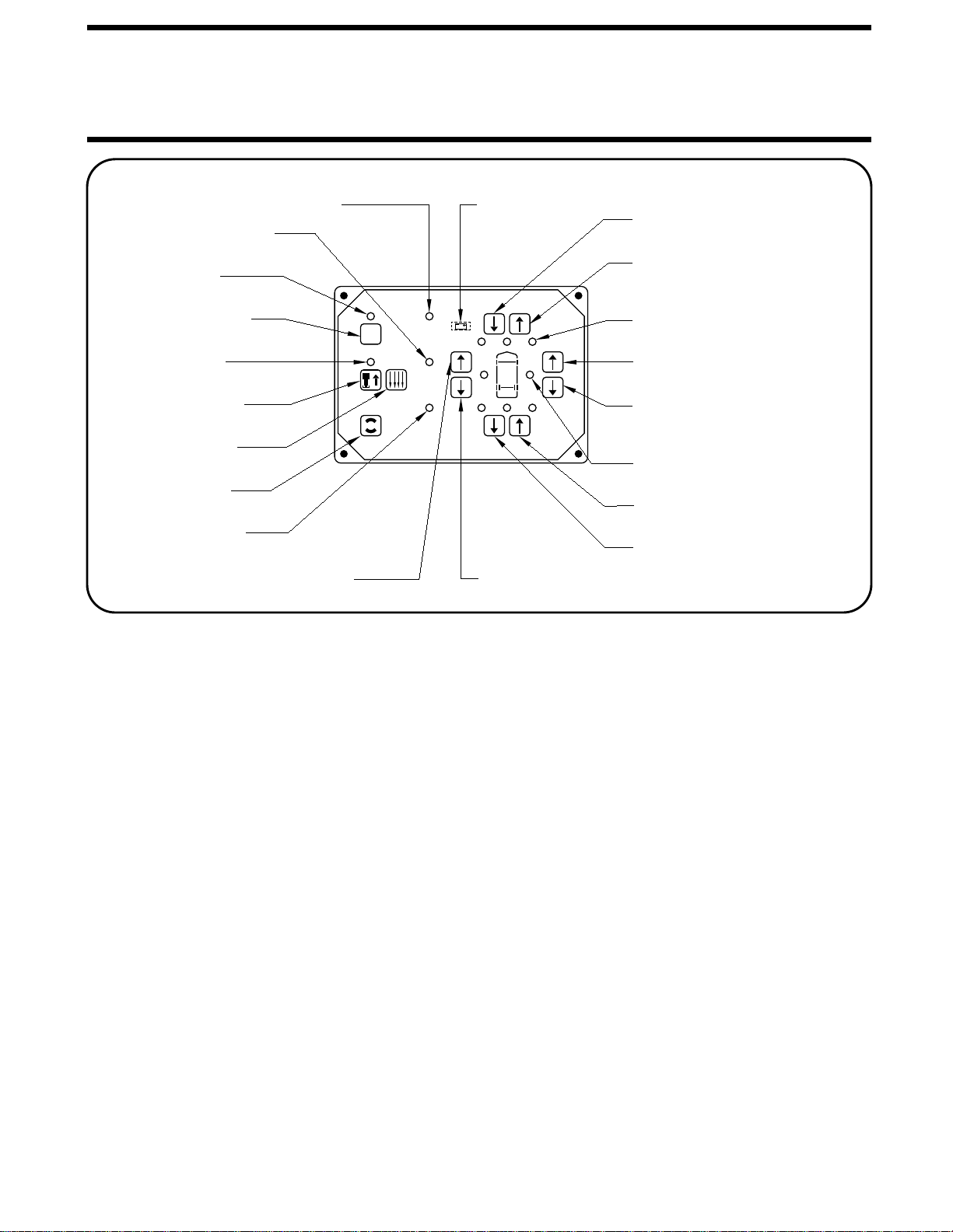
2. Press the "HYD" button to enter the hydraulic operation
mode. The "HYD" indicator light will glow steady.
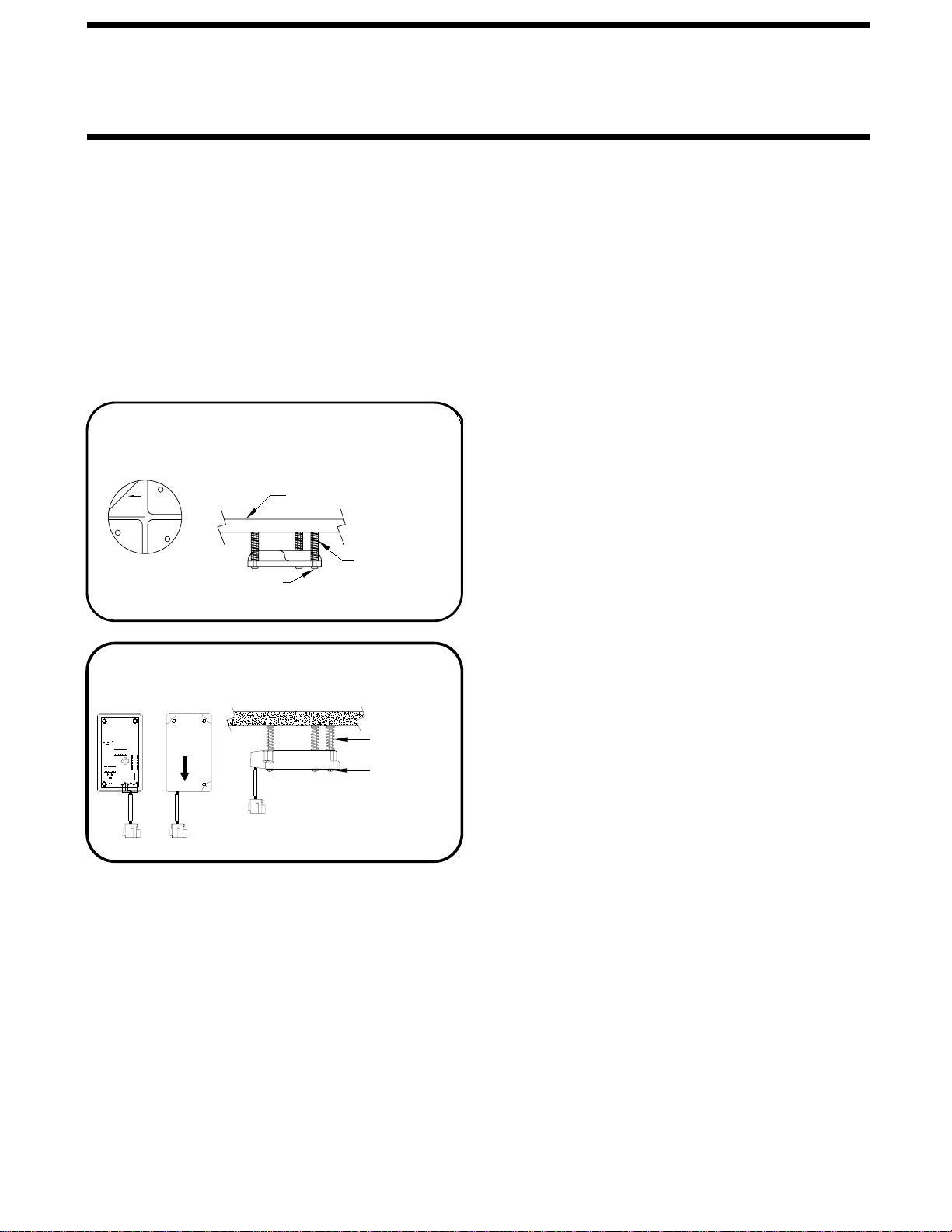
3. At this time, the operator may want to check the jacks and
place pads under the jacks if the ground will not support the
vehicle.
4. Press the "HYD" button a second time. The "HYD" indicator
light will start to flash. The system will begin to dump air from
the vehicle suspension. After approximately 25 seconds, the
system will automatically extend the jacks to level the vehicle
and then extend any remaining jacks until they touch the ground.
EXCESS SLOPE SITUATION: In the event the jacks are unable
to level the coach, the "EXCESS SLOPE" indicator light will
come on. The pump will shut off. One or two yellow leveling
indicator lights will remain on. The "HYD" indicator light will
continue to blink for 2 minutes, then the system will shut off.
The system will NOT stabilize the vehicle if the "EXCESS
SLOPE" light comes on. Store the jacks according to the JACK
RETRACTION Section. Move the vehicle to a more level
position or level the vehicle as close as possible according to
the MANUAL HYDRAULIC OPERATION Section.
5. Turn the ignition switch to the "OFF" position.
JACK RETRACTION
THE OPERATOR MUST BE SURE THAT
THERE ARE NO OBJECTS UNDER THE VEHICLE AND THAT
ALL PEOPLE ARE CLEAR OF THE VEHICLE.
DO NOT interrupt power to the leveling system
while the "STORE" indicator light is blinking. DO NOT push
the "OFF" button or turn the ignition key. The system must be
4. If jacks cannot be retracted by the above procedure see
MANUAL JACK RETRACTION Section.
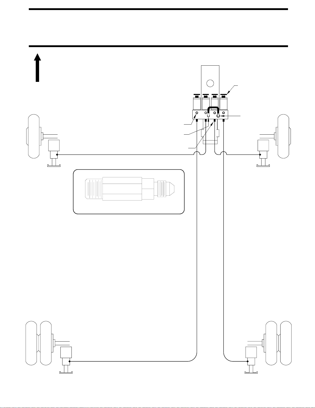
JACK POSITIONS
CAUTION:
DO NOT MOVE THE VEHICLE WHILE THE
LEVELING JACKS ARE STILL IN CONTACT WITH THE GROUND
OR IN THE EXTEND POSITION. THIS VEHICLE IS EQUIPPED
WITH STRAIGHT-ACTING JACKS. MOVING THE VEHICLE
WITH THE LEVELING JACKS EXTENDED CAN CAUSE
SEVERE DAMAGE TO THE JACKS AND OR THE VEHICLE AND
CREATE A DRIVING HAZARD. DO NOT RELY SOLELY UPON
WARNING LIGHTS. IT IS THE OPERATOR’S RESPONSIBILITY TO
CHECK THAT ALL JACKS ARE FULLY RETRACTED INTO
allowed to completely finish the STORE mode.
2. Press the "STORE" button. The store indicator light will
flash. As each jack retracts, its red WARNING light will go
out. The system will automatically shut down six minutes after
the four individual red "WARNING" lights are out. If any one
red "WARNING light does not go out, the system will continue
to store for thirty minutes, then shut down regardless of the
"WARNING" lights condition.
EXTEND POSITION STORE/TRAVEL POSITION
1. Start the engine to build air pressure in the suspension sys-
tem. Push the "HYD" button and store the jacks immediately.
3. The vehicle can be moved as soon as the red warning lights
THE STORE/TRAVEL POSITION AND THE VEHICLE IS AT
THE PROPER RIDE HEIGHT.
are out, the green "TRAVEL" light is on, and the suspension
air bags are inflated, and the vehicle has returned to the proper
ride height, providing the jacks are in the STORE/TRAVEL pos-
ition.
After the system has finished leveling and stabilizing, it will auto-
matically shut off.
NOTE:
When the "STORE" button is pushed, the air valves will
shift to the travel position and the vehicle will begin to return to
ride height.