HYBRYD CRYSTAL LED Manual

Centrally supplied emergency exit sign luminaire
1/4IMM - CRYSTAL LED - CB_CBAM_LV_LVAM - EN V04
IP40
CRYSTAL LED
INSTALLATION AND MAINTENANCE MANUAL
MOUNTING TYPE
Directly to the wall or ceiling. For other mounting types see: „Mounting
accessory” in product data sheet
OPERATING MODE
NM –NON-MAINTAINED – luminaire operates in emergency
mode after power supply failure
M–
MAINTAINED – lighting provided all the time, in case of
power supply failure switches automatically into emer-
gency mode
SYSTEM VARIANT
CB –luminaire supplied from HVCBS (230V AC/216V DC),
without address module
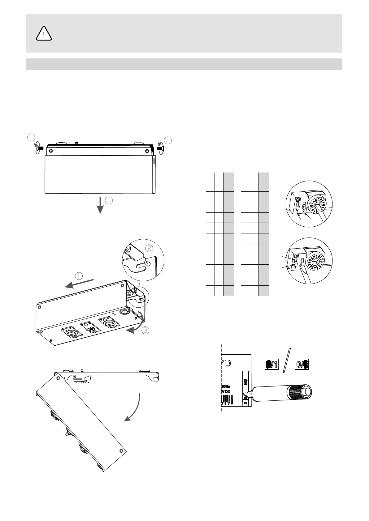
CBAM –
luminaire supplied from the HVCBS (230V AC
/216V DC), with built-in address module and operating
modeselection
LV – luminaire supplied with 24V DC
LVAM –
luminaire supplied with 24V DC from the LVDBS
system, with built-in address module and operating
modeselection
OPTICS
AREA –
(AR) symmetrical light distribution in all directions, rec-
ommended for use in places of considerable height or to
illuminate re points
ROAD PLUS
ROAD
AREA / AREA PLUS
AREA
PLUS –(AP) symmetrical light distribution in all directions, en-
suring adequate illumination on a large area
ROAD –(RO) light distribution mainly along the escape route, rec-
ommended for use in high corridors
ROAD
PLUS –
(RP) light distribution mainly along the escape route
with a much greater range than for the ROAD optics, for
smallheights
TECHNICAL DATA
Supply voltage
CB 230V AC 50/60Hz 80–275V DC
CBAM 230V AC 50/60HZ 170-275V DC
LV/LVAM 10–32V DC
Minimum luminous ux
(2W / 4W / 6W)
AR 220 / 417 / 642 lm
AP 175 / 331 / 508 lm
RO 177 / 368 / 563 lm
RP 127 / 351 / 537 lm
Protection class
CB/CBAM I
LV/LVAM III
Ingress protection IP40
Light source type LED modules 1)
Light colour temperature 5700K
Light source power 2W, 4W, 6W
Light source lifespan > 50 000h
Ambient temperature range
CB/CBAM -10 – +45˚C
LV/LVAM -25 – +65˚C
Supply cable cross-section area 0,5 – 2,5mm2
Supply cable diameter ≤ 13mm
Suitable for through wiring YES
1) Non-exchangeable, but serviceable light source
SAFETY
• During the installation and usage of emergency luminaires, follow the national safety rules as well as generally accepted technical rules
• Supply voltage should never be removed from the permanent phase by any external switches, relays or contactors (BMS, wall switch, etc.)
• During usage of emergency luminaires keep a register of inspectionreports
• Luminaire installation or maintenance has to be preceded by turning o the power supply and battery
• Ensure that all foreign bodies are removed before the luminaire power is switched on
• The luminaire is to be used undamaged and in accordance withspecications
THE ABOVE-MENTIONED LUMINAIRE IS A FIRE PROTECTION EQUIPMENT ANDTHEREFORE FALLS WITHIN RELEVANT STANDARDS AND REGULATIONS.
EN

2/4 www.hybryd.eu
NOT OBEYING THE SAFETY INSTRUCTIONS AND
RECOMMENDATIONS CAN CAUSE LIFE THREAT OR EVEN
DEATH
Not obeying this instruction manual can result
in luminaire damage and loss of warranty
DO NOT STARE AT THE OPERATING LIGHT SOURCE
The luminaire should be positioned so that
prolonged staring into the luminaire at
a distance closed than 0.5m is not expected
CONSTRUCTION
Housing
mounting screw
Outer housing
Light source
DIMENSIONS (mm)
61
173 63
123
26
WIRING DIAGRAM
N
N N PE PE L L
CRYSTAL LED
N N PE PE L L
CRYSTAL LED
PE
L
CB/CBAM
LV/LVAM
CRYSTAL LED CRYSTAL LED

3/4IMM - CRYSTAL LED - CB_CBAM_LV_LVAM - EN V04
BEFORE ANY INSTALLATION OR MAINTENANCE WORK IS PERFORMED ON THE LUMINAIRE
THE POWER SUPPLY SHOULD BE DISCONNECTED
All installation and maintenance procedures can be performed only by qualied,
properly trained and if appropriate, certied sta
INSTALLATION
1. Unpack the luminaire after transport and verify its condition.
2. Drill holes in ceiling according to mounting hole spacing (see
DIMENSIONS) and in the light direction (see OPTICS), so that the
cables coming from the ceiling go freely through the hole provid-
ed for this purpose. Use dowels and screws appropriate for the
material luminaire is being mounted to.
3. Remove the screws that secure the outer casing and removeit.
1
1
2
4. Slide the top plate horizontally to release the mechanical
catch from the pin.
1
2
3
5. Rotate the top cover to get an access to luminaire connectors.
6. Pass the power cables through the hole in the top plate, and
then screw the luminaire base to the ceiling.
7. Connect the luminaire power supply cables. The luminaire is
suitable for through wiring.
WARNING! The L phase has to be the same as the one used for the
supply of normal luminaires, where after power loss on it the lumi-
naire goes into emergency operation (permanent phase).
8. IIn case of luminaires with built-in address module:
a. set luminaire address using the rotary switch SW1 and second
slider of SW2 switch (SW2-2).
Setting the SW2-2 position to „1” means adding 10 to the address,
according to the table below.
SW2-2
SW1
Address
SW2-2
SW1
Address
0 1 1 1 1 11
0 2 2 1 2 12
0 3 3 1 3 13
0 4 4 1 4 14
0 5 5 1 5 15
0 6 6 1 6 16
0 7 7 1 7 17
0 8 8 1 8 18
0 9 9 1 9 19
0 A 10 1 A 20
SW2 SW1
SW2
SW1
„1“
„0“
SW2-1 SW2-2
b. using the rst slider of SW2 switch (SW2-1) select the
operating mode. Position „1”–maintained(M), position „0” – non-
maintained (NM).
9. Mark the operating mode on the luminaire label. Mark 0for
maintained mode
(M)
and 1for non-maintained mode
(NM)
.
M NM
.
10. Then do the reverse of steps 5, 4 and 3.
11. Perform the commissioning procedure.

4/4 www.hybryd.eu
COMMISSIONING
After all installation procedures are nished, luminaire operation needs to be veried.
Follow the instructions below:
1. Switch the luminaire power supply on the HVCBS (CB, CBAM) or LVDBS (LV, LVAM) system.
2. For luminaires without built-in address module (CB, LV):
a. Leave luminaire operating and verify light source operation – should be operating.
b. Turn o luminaire power supply.
3. For luminaires with built-in address module:
a. Congure the HVCBS/LVDBS system.
b. Congure HVCBS/LVDBS circuit as maintained.
c. If required, switch between maintained and non-maintained luminaire operating mode.
d. Run the functional test on HVCBS/LVDBS system.
e. Verify luminaire operation. The light source should operate properly.
f. Verify if the HVCBS/LVDBS system reports proper luminaire operation.
POTENTIAL IRREGULARITIES AND TROUBLESHOOTING
PROBLEM POSSIBLE CAUSE SOLUTION
After turning on the power thelight
source is o
Not connected or badly connected
power cords.
Make sure the power cables are properly connected to the
power connector inside the luminaire.
No power supply in the cables
connected to the luminaire.
Using a voltage detector, check the cables connected to
theluminaire has appropriate supply voltage.
MAINTENANCE
Luminaire should be cleaned with a damp cloth according to building maintenance plan.
Do not use abrasive cleaners, solvents, substances and cleaning agents containing alcohol to clean the luminaire
The light source used in this luminaire may only be replaced by the manufacturer, his service agent or a similar qualied person.
STORAGE
The luminaire should be stored no longer than 6 months from the date of purchase, in a dry place with an ambient temperature range of
-10 – +30˚C.
WARRANTY
Warranty is valid and enforceable only when manufacturer’s recommendations are preserved, and the installation and usage are proper.
Warranty is granted for a period of 12 months from the date of sale, unless the luminaire has been sold under dierent contract conditions.
The warranty is excluded in case ofmisuse, unsuitable use, wrong connection or mechanical defects of the luminaire caused by the client.
Other HYBRYD Lighting Equipment manuals