2
P/N 21144607 10/05
IMPORTANT! WRITE MODEL NUMBER FROM BOX ONTO PAGE 1 OF THIS OWNERS MANUAL
WARNING
FAILURE TO FOLLOW THESE WARNINGS MAY RESULT
IN SERIOUS INJURY AND/OR PROPERTY DAMAGE.
Owner must ensure that all players know and follow
these rules for safe operation of the system.
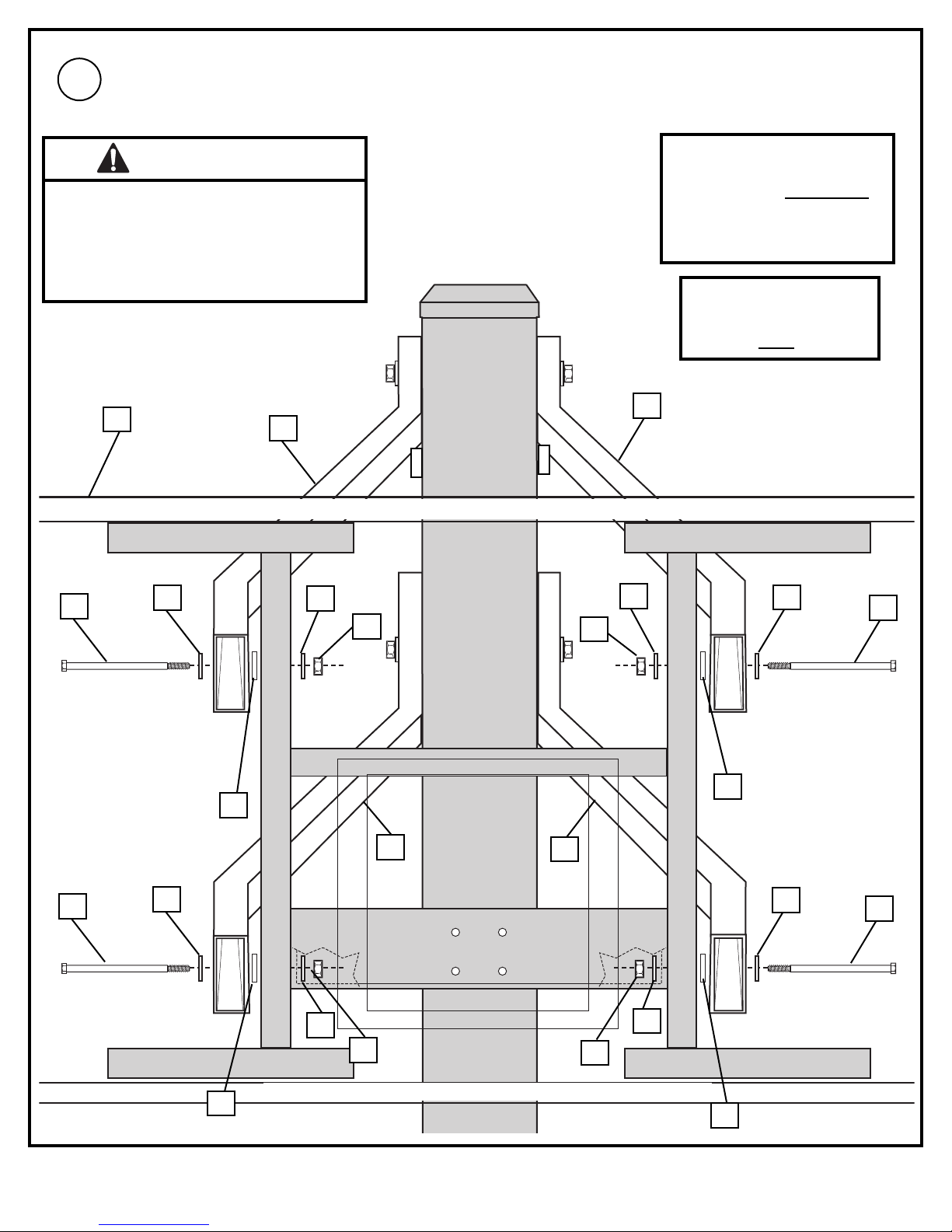
• See instruction manual for proper installation.
• DO NOTHANG on the rim or any part of the system
including backboard,suppor t braces or net.
• During play,especiall y when performing dunk type
activities,keep player's face away from the backboard,rim
and net.Serious injury could occur if teeth/face come in
contact with backboard,rim or net.
• Do not slide,c limb,shake or play on pole.
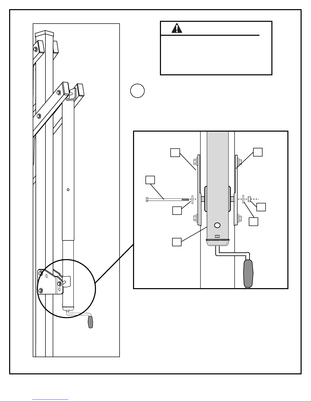
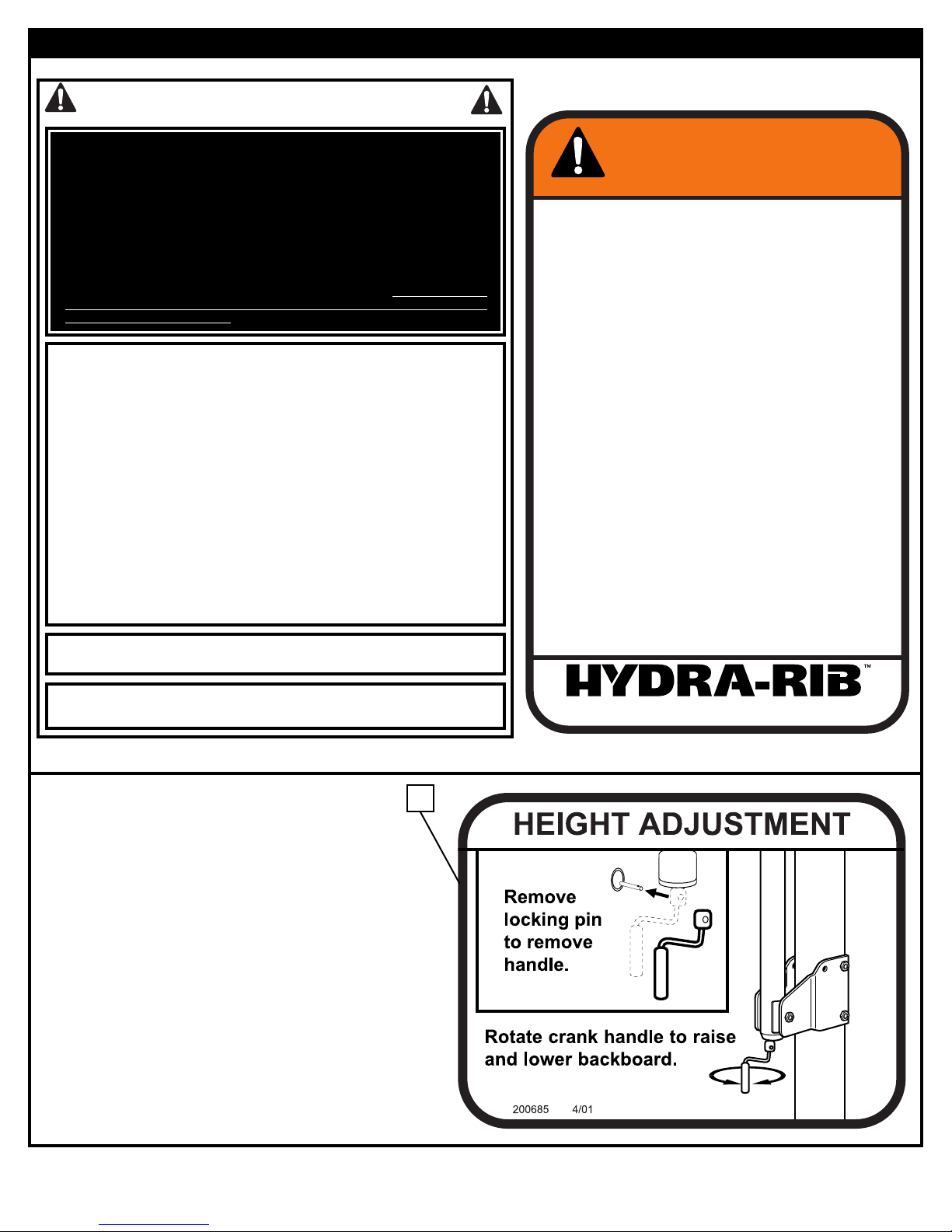
• When adjusting height,keep hands and fingers away from
moving parts.
• Do not allow children to move or adjust system.
• During play,do not wear jewelry (rings,watc hes,
necklaces,etc.);objects may entangle in net.
• K eep organic material away from pole base.Grass,litter ,
etc.could cause corrosion and or deterioration.
• Chec k pole system for signs of corrosion (rust,pitting,
chipping) and repaint with with exterior enamel paint.If
rust has penetrated through the steel anywhere,replace
the pole immediately.
• Chec k system before each use for proper ballast,loose
hardware,e xcessive wear and signs corrosion and repair
before using.
• Chec k system before each use for instability.
• Ne ver play on damaged equipment.
• K eep pole top covered with cap at all times.
201255 2/99
1-800-558-5234
CRANK : ADJUSTMENT
HYDRA-RIB IN-GROUND
200685
26
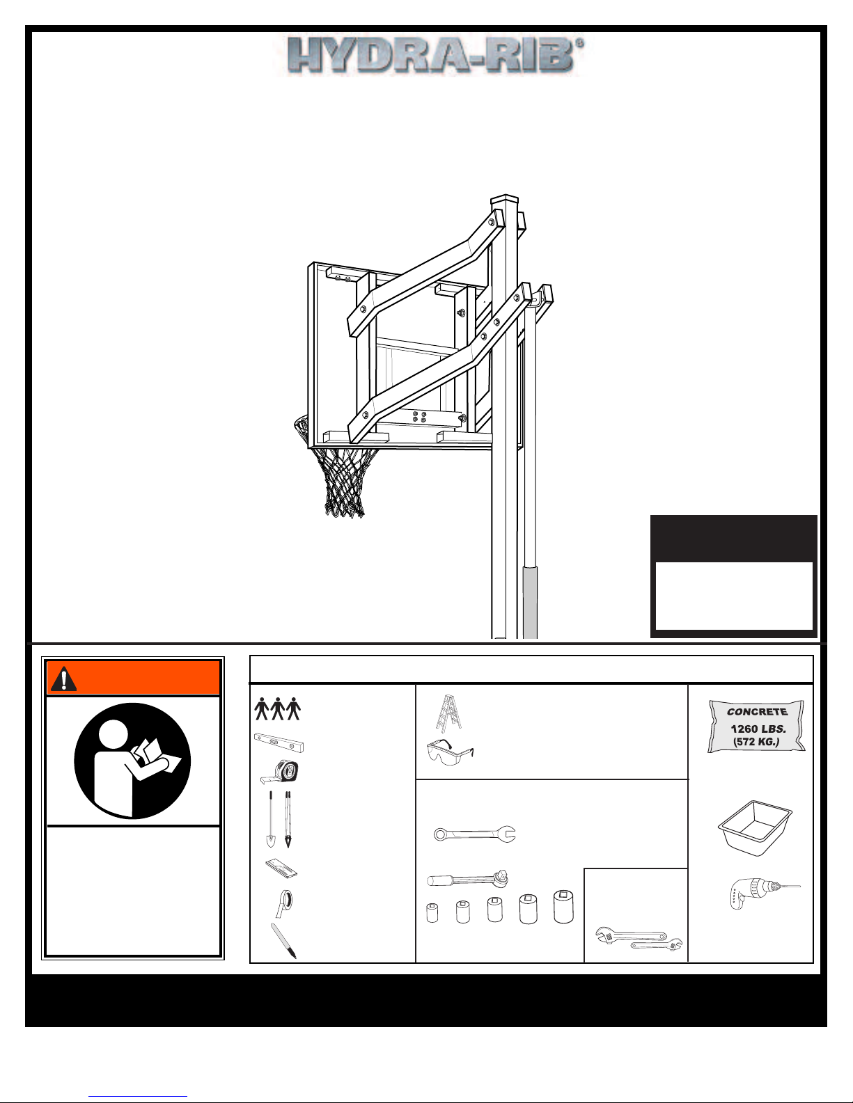
SAFETY INSTRUCTIONS
Most injuries are caused by misuse and/or not following instructions.
Use caution when using this system.
• If using a ladder during assembly, use extreme caution.
• Three (3) people are reccomended for this operation.
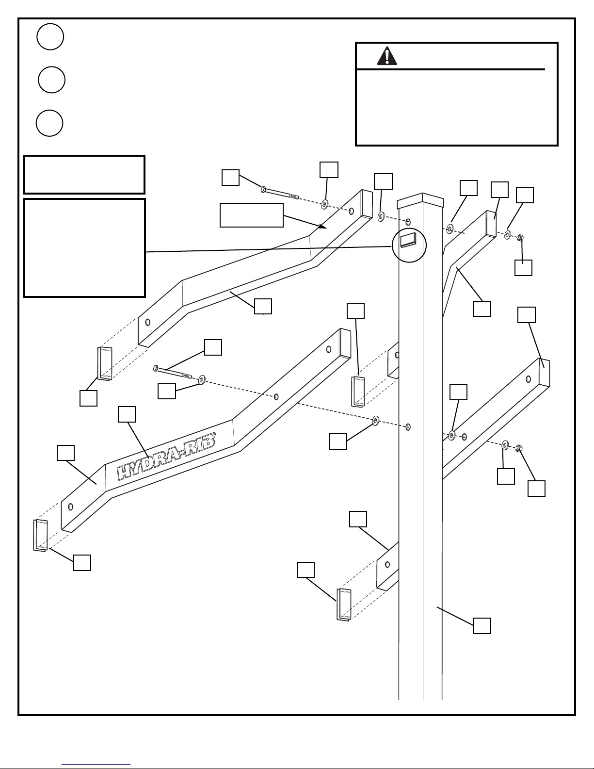
• Seat the pole sections properly. Failure to do so could allow the pole sections to
separate during play.
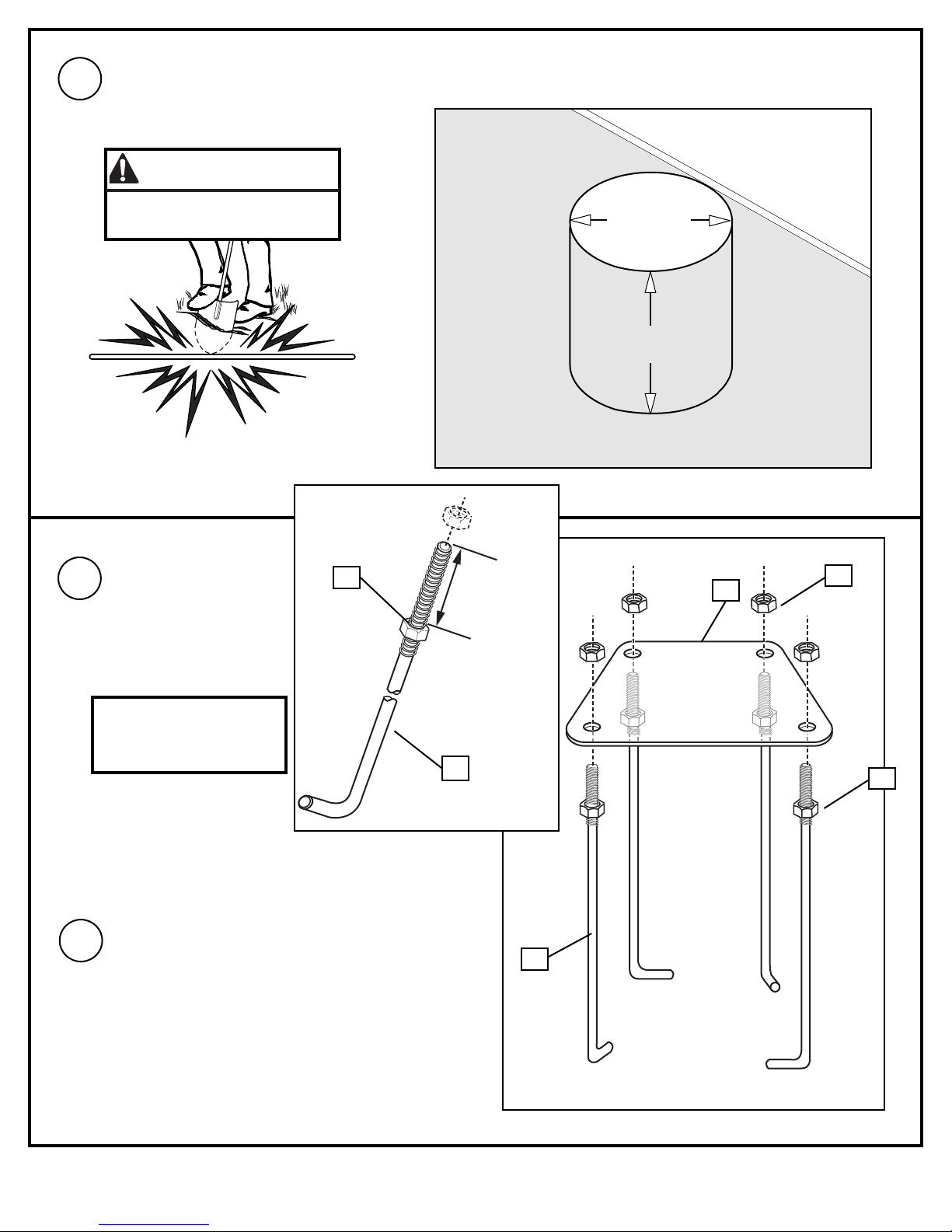
• Before digging, contact utility company to locate underground power cables, gas,
and water lines. Ensure there are no overhead power lines within 20 ft. (7 m) radius
of pole location.
• Climate, corrosion, excessive use, or misuse could result in system failure.
•If technical assistance is required, contact Huffy Sports.
• Minimum operational height is 6'6" (1.98 m) to the bottom of backboard.
• This equipment is intended for home recreational use only and NOT excessive
competitive play.
• Read and understand the warning label affixed to pole. Label is shown on page 2.
• The life of your basketball pole depends on many conditions. The climate,
placement of the pole, the location of the pole, exposure to corrosives such as
pesticides, herbicides or salts are all important.
• Adult supervision is recommended when adjusting height.
•Serious injury could occur if teeth/face come in contact with backboard, net, or rim.
FAILURE TO FOLLOW THESE SAFETY INSTRUCTIONS MAY RESULT IN
SERIOUS INJURY, PROPERTY DAMAGE AND WILL VOID WARRANTY.
Owner must ensure that all players know and
follow these rules for safe operation of the system.
To ensure safety, do not attempt to assemble this system without following the
instructions carefully. Proper and complete assembly, use and supervision is
essential for proper operation and to reduce the risk of accident or injury. A
high probability of serious injury exists if this system is not installed,
maintained, and operated properly. Check entire box and inside all packing
material for parts and/or additional instructional material. Before beginning
assembly, read the instructions and identify parts using the hardware identifier
and parts list in this document.
For more information on assembly, placement, proper use and maintenance,
visit The American Basketball Council website at http://www.smarthoops.com.