Hydra ZODIAC User manual

HYDRA EVC LTD | ✆
01268 205 121
| www.hydraev.co.uk | support@hydraev.co.uk
This is a quick-connection
guide only. To view the full
installation manual for this
and all Hydra EV chargers
go to www.hydraev.co.uk/support
ZODIAC
ELECTRIC VEHICLE CHARGER
QUICK INSTALLATION GUIDE
INSTALLATION USING QUICK-CONNECT FLY LEAD
PLEASE NOTE: THE ZODIAC HAS BEEN DESIGNED TO BE CONNECTED USING THE QUICK-CONNECT FLY LEAD. THIS SIMPLIFIES
THE INSTALLATION PROCESS AND ENSURES THE ELECTRONIC COMPONENTS WITHIN THE EV CHARGER HOUSING ARE NOT
DISTURBED. IT ALSO ALLOWS THE ZODIAC TO BE WALL OR PEDESTAL MOUNTED BEFORE IT IS CONNECTED TO THE AC SUPPLY.
INSTALLATION
Secure the base to the wall. NB: To avoid the back plate distorting when being screwed onto the wall, it is
recommended that you x each screw loosely one at a time and then tighten slowly once all screws are in place.
Carefully and slowly lower the charger into place.
Ensure that the cabinet holes and bolts are aligned.
Lock the nuts to 95.5 Nm.
Keep the device upright – do not tilt more than ±15°
Mount the charging pile on the hanger and lock the charging pile
Wall xing bolts
(using suitable rawlplugs
where appropriate) Mounting
screws
Mounting backplate

HYDRA EVC LTD | ✆
01268 205 121
| www.hydraev.co.uk | support@hydraev.co.uk
CONNECT THE POWER CABLE
Note: Turn off switches and pull out all fuses before connecting electrically
PE NL
CONNECT THE GROUND CABLE
The charging system uses a common grounding method, using a ground cable to connect the
ground copper row of the charging unit with the main ground row.
CONNECT THE AC INPUT
1The AC input cable is routed from the user’s power distribution switch and is connected to the output
terminal of the user switch when power is ready to be turned on. The user distribution switch should
have over-current, short circuit, lightning strike and other protective devices. The capacity of the power
distribution switch is recommended as not less than 1.5 times the actual load capacity.
Please ensure the The Zodiac has its own dedicated circuit – EV charging equipment in the UK is
required by law to have its own dedicated circuit.
2The L1-phase, L2-phase, L3-phase and N-zero cables of the AC input cable should use brown,
black, grey and blue cables (standard reference right). If the cable has only one colour, the line
number identication is pasted or marked with different colour insulation at both ends of the cable.
3Cables should not have severed heads, broken heads or scratches.
Yellow/Green PE
Brown L
Blue N
INSTALLATION WITHOUT USING QUICK-CONNECT FLY LEAD
OPENING THE ZODIAC EV CHARGER HOUSING
The faceplate of the Zodiac EV charger is held in place with six small
screws (three each side). These cannot be accessed once the EV
charger has been mounted onto the wall.
Lay the Zodiac face down on a level surface taking great care not to scratch
the faceplate. Use the foam sheets from the original packaging to protect it.
In addition to the power cables to the charging socket (Untethered version)
there is a communications antenna wire (black) and power cable to the LED
status indicator light (white/red ribbon) attached to the back of the faceplate.
On some models there is an additional antenna wire (black) for the RFID
card reader.
It is vitally important to the function of the EV charger that these wires
are undisturbed.

HYDRA EVC LTD | ✆
01268 205 121
| www.hydraev.co.uk | support@hydraev.co.uk
Faceplate LED status indicator
power cable
Communications
Antenna
CT clamp
(note orientation
- see below)
Charge Socket
INSIDE THE ZODIAC EV CHARGER (UNTETHERED MODEL)
Power-in
Connection
Above shows a single-phase 7kW Hydra Zodiac with the
Power Cable attached. The terminals on this model (from
left) are PE, L, N
Please always check the board for correct orientation
and wiring order. Some Zodiac models may be
congured as PE, N, L (see below for location)
A 5-terminal block is tted to the 22kW, three-phase
model, and also on some 7kW models. (see below)
Here the terminals are designated PE, N, L1, L2, L3
Always check wiring order marked on PCB
Always note the CT orientation, where tted (see bottom)
Please make sure that the orientation of the CT clamp is correct (where tted): The Black/Red wire exiting the CT
clamp should face the direction of the board to achieve a correct reading. If the side of the CT clamp with these wires
is facing away from the board it will not give accurate readings.
For the three-phase Hydra Zodiac (below right) each CT clamp needs to be re-attached to the correct feed and with
the correct orientation (black/red wire facing the board).
(Please Note: Some models take the reading direct from the board and no separate CT clamp is used)
CT CLAMP ORIENTATION
PE
N
L1
L2
L3

POWER-ON PROCESS
Ensure that the charger is installed properly and attached securely to the wall. Check that the wires are wired
correctly and the charger can be powered up.
After the Zodiac charger is powered up the LED indicator light on the faceplate should be blue, either ashing or
steady and constant.
If it does not show a blue indicator light please refer to the appendix of the manual where it describes different LED
indicator status lights.
CHARGING OPERATION
There are two methods to commence charging: simple Plug and Play or via the smart-phone App, HOMECHARGE.
Before charging, please make sure that the charging cable is rmly inserted into the charging port of the vehicle.
If you intend to use the App to facilitate charging, please use the APP to scan the QR code when using it for the rst
time, and turn on Bluetooth of the smart-phone for Bluetooth networking. After the pairing process is completed,
follow the App prompts to commence charging.
Click the charger information in the App to view the current output capability of the
Zodiac EV charger and information of the running status.
If the running status displays an alarm or error message, charging cannot be
performed. You will need to go through the troubleshooting process outlined at the
end of this document.
When the preselected charge level is reached or the vehicle sends a stop
command, the charger automatically stops charging.
EMERGENCY OPERATION
Refer to this section only if an exception has occurred or the charger has been mishandled.
Emergency stop: In the event of an emergency, quickly remove the transparent
protective cover (if present) and press the metal/silver Emergency Stop button to cut off
the output power supply. Do not use the Emergency Stop button for normal shut-down.
Emergency
Stop button
and its
location
(right hand
side of the
Zodiac if
facing the
charger)
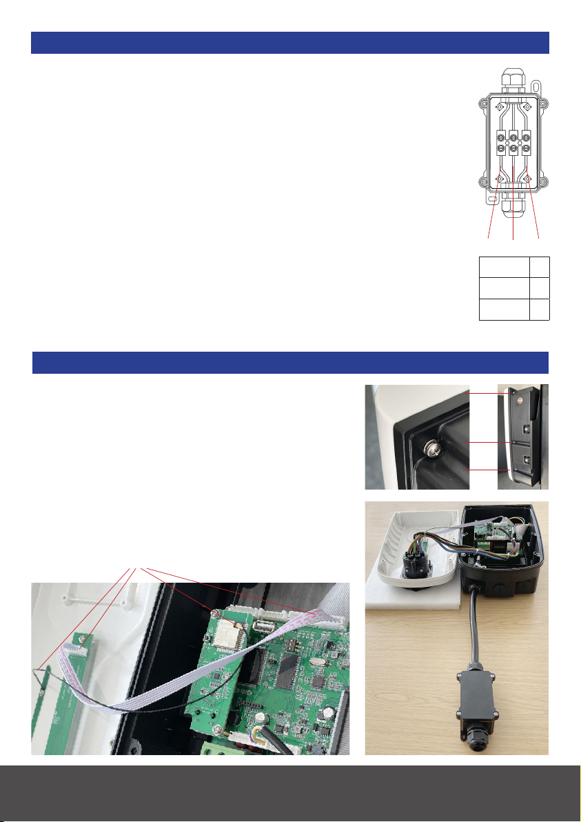
ACCESS PORTS UNDER THE ZODIAC CHARGER
The Hydra Zodiac has three access ports
underneath, these are for:
Power in (LEFT on all models),
RJ45 Ethernet cable (CENTRE on some models),
Charging Cable Out (RIGHT on tethered models) RJ45 Ethernet port
(centre on some models)
HYDRA EVC LTD | ✆
01268 205 121
| www.hydraev.co.uk | support@hydraev.co.uk
Other manuals for ZODIAC
1
Popular Automobile Batteries Charger manuals by other brands

Charge Amps
Charge Amps Amp Guard installation manual

Blue point
Blue point EEBC100A manual

Schumacher Electric
Schumacher Electric SC1402 owner's manual

Ferm
Ferm BCM1017 Original instructions

PulseTech
PulseTech X2 xtreme charge Feature and use guide

Power Electronics
Power Electronics Ford Pro Standalone NB 240 manual