Hydreon RG-11 Instruction Manual

LENS
O-RING
STRETCH BEFORE
INSTALLING
SHADE
NOTCHES IN RING
MATE WITH
RIBS IN LENS
PRINTED-CIRCUIT
BOARD (PCB)
SCREWS
(4 OF #6 X 1”)
HOUSING
19.16
.75
10.40
.41
6.40
.25
19.05
.75
9.53
.38
70.71
2.78
120.23
4.73
55.20
2.17
OPTICAL RAIN GAUGE
MODEL RG-11
INSTALLING THE RAIN SENSOR
1. Determine the Mode / Set DIP switches
You must set the DIP switches so that the RG-11
behaves the right way for your application. The pages
that follow describe each of the possible modes, and
how to set the DIP switches.
2. Mount the Rain Gauge
Mount the rain gage where it gets a clear measurement
of precipitation– away from overhangs, etc.
The mounting arm is designed to fit over a strap 0.75”
(19 mm) wide. Two 0.25” (holes 6.35 mm) are placed
0.75” (19 mm) part.
The gland style connector goes in the bottom hole. Be
sure to use wire rated for outdoor (high-UV) use.
For conduit applications, the mounting arm may be
removed, and the wiring hole drilled out using a step drill
to accommodate a ½” EMT compression connector or
similar style of conduit connector.
3. Assemble the Rain Gauge as shown.
Stretch and release the silicone o-ring (size -036) a few
times, so it fits easily in the groove. Optionally, you may
coat the O-ring and screws with silicone grease.
The Rain Gage must be assembled when dry. Any
water trapped inside can condense and cause corrosion.
You may optionally add extra desiccant packets (not
supplied.) If the Rain Gage is not subject to splashing or
sprayed water, you may optionally vent the enclosure by
drilling a 1/8” (3 mm) hole in the bottom of the case.
MOUNTING ARM
CUT OFF FOR
CONDUIT-MOUNT
LED ON BOARD
ON when OUT
is active
EXPLODED VIEW
- APPLICATION WARNING -
Do not use the RG-11 in any application where the false
indication of water or a missed valid detection of water
could cause damage to life or property. It is the
responsibility of the system designer / integrator to
design redundancy into the system so that the failure of
any one component, including the RG-11 or other
sensor, does not result in disaster. The manufacturer of
the RG-11, Hydreon Corporation, will in no way be
liable for consequential damages due to the failure or
false indication of one of its sensors.
!VERY IMPORTANT
Stretch the O-ring a few times, so that it fits
easily into the groove on the lens.
!
!
After the unit is assembled, verify that the O-ring is properly
seated by confirming that you can see it through the lens, all
the way around. The O-ring is slightly under-sized for the
groove because that gives the optimal seal.

NC
NO
MOTORIZED
DAMPER
LOW VOLTAGE
“IT’S RAINING”
APPLICATION
LINE VOLTAGE CONTROL “IT’S RAINING” APPLICATION
NC
NO
PWR2
COM
RG-11
PWR1
SWITCH ON
RELAY
CONTACTS
POWER IN
(AC OR DC)
PROGRAM /
COMMUNICATIONS
CONNECTOR
(NOT USED IN MOST
APPLICATION)
INTERFACE
TERMINAL
BLOCK
PROGRAMMING
DIP SWITCH
RAIN GAUGE CONNECTIONS
NC
NO
COM
RAIN
SENSING
CIRCUITS
DC OR
AC IN
PWR1
PWR2
EQUIVALENT SCHEMATIC
RELAY CONTACTS
MAX 1 A,
24V DC OR AC
NC
NO
PWR2
COM
RG-11
PWR1
SWITCH ON
120 VAC
LINE IN
COM
OPEN
CLOSED
OPERATOR
SWITCH COM
24 VAC
24 VAC
TRANSFORMER
- The relay output of the RG-11 is
rated for 24V AC or DC, at 1 A. Thus,
the RG-11 cannot drive a line voltage
(120 VAC) load without an external
relay.
-The RG-11 requires a low voltage AC
or DC supply and may not be directly
powered from the 120 VAC line.
12345678
12345678
For this example, these
switches are on:
SW 5 - Sets the sensor to
“It’s Raining’ mode.
SW 3 - Monostable extend
output for 15 mintues.
NC
NO
PWR2
COM
RG-11
PWR1
COM
RUN
12V DC
POWER
SUPPLY
12V DC, 1 A
OR LESS,
MOTOR THAT
RUNS WHEN
IT IS RAINING.
Shown are
switches 1, 2, and
5 on => only turn
on in a heavy
rainfall.
TIPPING BUCKET
REPLACEMENT EXAMPLE
NC
NO
PWR2
COM
RG-11
PWR1
12V DC
POWER
SUPPLY
COUNTER
E.G. Red Lion Cub-3
+
-
+
-
In many cases, the RG-11 may directly replace
tipping buckets in existing systems.
The switch settings shown here- all off– will
emulate a tipping bucket of 0.01”
RAIN GAUGE WIRING EXAMPLES
SWITCH ON
12345678
SWITCH ON
12345678

Specifications
Parameter Value
Input Voltage 9 – 30VDC or
9 – 26 VAC
50V surge
Reverse polarity protecte to 50V
Current Drain 15 mA nominal. (No outputs on, not raining,
no heater)
about 1.5 mA in micro-power sleep mo e.
50 mA with output on.
55 mA - With heater on, 24V c input.
Output Relay closure, Normally Open an Normally
Close contacts.
Max loa 1A, 24 VDC.
Operating Temperature
range
-40 C to +60C
DIP Switches
Set the DIP switches for the application accor ing to the table below.
Generally, a few switch positions (5, 6, an 7) set the overall mo e of
operation, an others (1, 2, 3, 4) a just the behavior within the mo es. In the
tables, 1 = Switch on, 0 = Switch off, X = switch in either position.
Software Revision
This manual correspon s to software revision 011. The software revision is
printe on a sticker place on the connector block. See www.rainsensors.com
(click on “support”) for information about ifferences in software revisions.
Differences are generally minor.
Switch 8 is Enable Micro power Sleep Mode in most applications.
Most applications will use SW 8 off. If micro-power is enable , the low-
power heater is isable . In micro-power mo e, if a long time (about 20 min)
has elapse since the last rain was etecte , the unit will enter a less
sensitive sleep mo e. A large rop will cause it to exit sleep mo e an
resume normal operation. This is for battery or solar powere applications.
Micro-power mo e is isable in Con ensation sensing mo e an in irrigation
mo e. The unit will not rea the DIP switches uring sleep.
OUT LED The LED in the center of the circuit boar turns on when OUT is on,
as an ai to ebugging.
Condensation Generally, the RG-11 will sense con ensation as if it were
rainfall, but this sel om amounts to a significant accumulation of water. The
built-in low power heater (DIP SW 8 off) will ten to e uce con ensation.
Ambient Light Interference The RG-11 is almost completely immune to
the effects of ambient light, an may freely be mounte in irect sunlight.
Heater Notes– A built-in low power (0.25W) heater exten s operation of the
evice to freezing (32 F or 0C). This is isable if the micro-power (SW 8) is
enable . Note that this is a very mo est amount of power; it will ten to rive
off a mo est amount of frost, but will not melt ice.
Dark Sensing - Turns output on when it is usk-- nominally less than 2000
lux. This is for applications such as retracting sun-shiel s in the evening,
when they are not nee e . (Only in Mo e 1, “It's Raining” applications.)
J2 Connector
J2 is a pin-fiel on 0.1” centers, use for programming, evelopment, an
testing of the RG-11. Most applications o connect to J2, an we make this
information available only for special applications.
Connector fiel is 0.025” square pins on 0.1” centers. An example compatible
connector is Molex part number 22-01-3067. This is available from Digi-Key
as part number WM2004-ND. The necessary crimp-on wire terminals are
Molex 08-55-0131 / DigiKey WM4591-ND.
J2 Pin assignments
J2 - 1 GND
J2 - 2 + 5V
J2 - 3 SW4
J2 - 4 SW1
J2 - 5 SW2
J2 - 6 RS232 an SW 5.
External 5V Supply The RG-11 can be powere by an external regulate 5V
supply via the J2 connector. This can be useful in solar power applications.
Do not subject the RG-11 to over 5.5V or you coul amage it.
Remote Switching These connections may be use to remotely operate the
correspon ing switches, by groun ing the connections. This can be use for
operator-accessible sensitivity a justment in wiper control applications.
RS 232 communications – requires an external resistor. See the “support”
link on www.rainsensors.com. Mo es that require SW 5 on (It's Raining an
Wiper Control.) cannot use RS-232.
Rain Gauge Mo el RG-11 Instructions PN 55-005-100 rev 012

Mode 0 Tipping Bucket
Rain Gauge emulates a tipping bucket of the
specifie size.
Switch
Behavior
7 6 5 4 3 2 1
0 0 0 X 0 0 0 Bucket Size = 0.01”
0 0 1 Bucket Size = 0.001” (Sensitive)
0 1 0 Bucket Size = 0.0001” (Very sensitive)
1 0 0 Bucket Size = 0.2 mm
1 0 1 Bucket Size = 0.01 mm (sensitive)
1 1 0 Bucket Size = 0.001 mm (Very sensitive)
1 1 1 1 Reserve for system test
In tipping bucket mo e, the Rain Gauge effectively emulates a tipping bucket
of the specifie size. For example, if the DIP switches are set to a tipping
bucket mo e with a bucket size of 0.01", then the output will pulse ON for
50mS each time 0.01" of water accumulates, just as a tipping bucket woul .
This can be externally totalize , an use to measure rainfall rates. Bucket
sizes of 0.001" an 0.0001" are similar, generating pulses at accumulations of
one one-thousan th, an one ten-thousan s of an inch, respectively. These
emulate what a tipping bucket woul o if it were possible to make one that
small. Metric bucket sizes are available as well, or the Inch unit scales may
be scale with external equipment.
For best accuracy tipping bucket applications, we recommend annual
treatment of the rain sensor lens with Rain X. The Rain-X prevents a
con ition where the RG rea s high because water roplets stuck on the
sensor get blown by the win , causing high rea ings. With Rain-X, larger
roplets run off.
Mode 1 It's Raining
Rain Gauge turns on the relay to in icate that it
is raining when the rainfall has reache a given
intensity.
Switch
Function
7 6 5 4 3 2 1
0 0 1 X X 0 0 Very sensitive-- first etecte rain rop.
0 1 Sensitive-- turn on with very light rainfall
(0.1” per hour ).
1 0 Me ium Sensitivity-- turn on with me ium
rain (0.25” per hour. You woul want your
car's wipers on stea y slow)
1 1 Low Sensitivity-- turn on in heavy rainfall.
(1” per hour. You woul want your car's
wipers on high)
X 0 X X Output off when rain stops.
1 Output Monostable Exten e by 15
minutes
0 X X X No Dark-Detect - Normal operation
1 Dark Detect
Use this mo e to control equipment that shoul be controlle ,
enable , open, close , an so forth epen ing on whether or not it is
raining. The output turns on when a given rate of rainfall is etecte ,
an turns off after it has roppe below a threshol .
Each of the sensitivity levels (set by switches 1 an 2) provi es
ifferent trip an release points. There is much hysteresis built in, but
real rain fall rates typically fluctuate, even in what you may perceive
as a “stea y rain”, so expect the output to turn on an off. The output
will remain on for between about 30 secon s an 5 minutes after the
last etecte rain rop, epen ing on sensitivity setting an actual
con itions.
To prevent some piece of equipment from turning constantly on an
off (or opening / closing, etc.) you can enable the Monostable exten
(Switch 3). That will hol the output on for 15 minutes after the rain
has cease .
Dark Detect-- if this enable , the output will also turn on when the
ambient light rops below about 2000 lux. This feature may be use
to retract a sun-sha e awning when it is ark.
Mode 2 Condensation Sensor
Rain Gauge etects con ensation or frost
formation on the surface.
Switch
Behavior
7 6 5 4 3 2 1
0 1 0 0 0 0 0 Very Sensitive- first sign of con ensation
0 1 Sensitive
1 0 Me ium Low
1 1 Low
The rain sensor senses con ensation by etecting a shift from the
"clear" con ition. The relay closes when the con ensation occurs,
an opens when the con ensation goes away. The rain sensor is set
to very gra ually a apt the clear con ition, so that very gra ual buil
up of irt or other contaminants o not cause a false trip.
Con ensation sensing mo e isables the heater an micro-power
mo e.
Rain Gauge Mo el RG-11 Instructions PN 55-005-100 rev 012

Mode 3 Wiper Control
Rain sensing wiper control from off through
intermittent an stea y slow spee s.
Switch
Behavior
7 6 5 4 3 2 1
0 1 1 0 x 0 0 Normal Wiper Control
0 0 1 Wipe More
0 1 0 Wipe a Lot More
0 1 1 Wipe a Whole Lot More
1 0 0 Wipe Less
1 0 1 Wipe a Lot Less
1 1 0 Wipe a Whole Lot Less
1 1 1 Wipe har ly at all
x 0 x x Normal Slow Cycle Time (1.2 to 3 sec.)
1Long Slow Cycle Time (3 – 8 sec.)
See rainsensors.com for instructions that are just for wiper
control applications. (Click on “Wiper Control”).
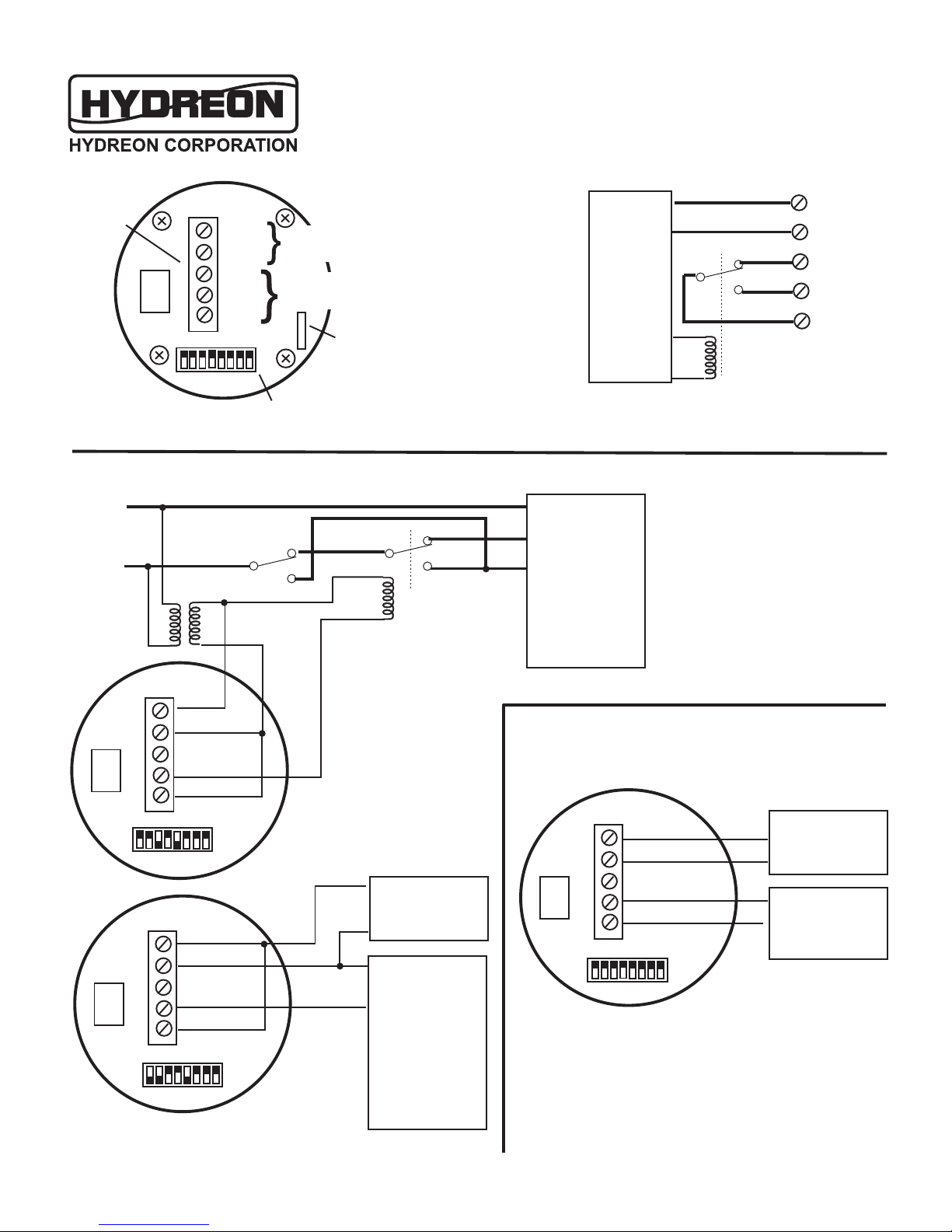
The RG-11 may be use to control a wiper system. The output relay
turns on when the slow motor win ing shoul be engage . This will
typically be use to rive an external relay, which will in turn rive the
wiper motor win ings. This may be use for the wipers for a boat,
ship, locomotive, observation win ow, or many other applications.
The RG-11 oes not care what the wipers are wiping.
WARNING: The relay contacts of the RG-11 can control only a 1A
loa , an wiper systems generally require many times that current.
The RG-11 MUST be use with a suitable external relay in wiper
control applications.
The nominal wiper control is set so that it properly controls the wipers
of a passenger car. It is optimize for wiper systems that require
between 1.2 an 3 secon s to make a single complete actuation of
the wipers. A long cycle time is provi e (Switch 4 on) for systems
with a wiper actuation cycle time between 3 an 8 secon s. In all
cases, the RG-11 provi es a pulse to initiate the wiper actuation.
Most wiper system will inclu e some sort of cam fee back
mechanism that causes the wipers to keep running until they reach a
home position.
Mount the RG-11 so that it generally gets the same rainfall as the
surface to be wipe . Usually, this means about a 45 egree angle.
The RG-11 oes not nee to be within the actual fiel of view of the
win ow. A just the sensitivity control DIP switches (3, 2, an 1) to
set the system to wipe more or less, epen ing on the nee s of the
installation.
Mode 4: Irrigation Control
Rain Gauge output on means inhibit watering.
Switch
Behavior
8 7 6 5 4 3 2 1
X 1 0 X X 0 0 0 Typical Water Control. Inhibit
watering for up to 5 ays.
0 0 1 Water More
0 1 0 Water a lot more
1 0 0 Water Less
1 0 1 Water a lot less
0 X X X Inhibit irrigation uring a storm
1 Allow irrigation uring a storm
0 X X X X Inhibit irrigation uring freeze
1 Allow irrigation uring freeze
0 Normal Evaporation Rate
1 Hi Evaporation Rate
See rainsensors.com for instructions that are just for irrigation
control applications. (Click on “Irrigation Control”)
The RG-11 may be set to provi e precise control of an irrigation
system. Typically, the installation will connect to the COM an NC
relay contacts to interrupt the valves when watering shoul be
inhibite . Note that the RG-11 also requires 24 VAC (or other
suitable supply.)
The nominal irrigation profile is set so that the groun receives an
inch of water per week. It will inhibit watering upon the accumulation
of 0.2 inches of water, an re-enable the system after that water has
evaporate . This can be a short as less than a ay, or as long as six
ays, epen ing on rainfall. A itional DIP switch settings are
provi e for allowing more or less watering, as shown in the table
below.
Nominally (Switch 4 off), the RG-11 will inhibit watering uring a
storm, even if not much water has accumulate . The reasoning is
that if it is raining har now, the rainfall is likely to eliver enough
accumulation to justify inhibiting at least the current cycle of watering.
This prevents the “it's pouring, but my sprinklers are still running”
objection from the customer, an the accompanying excessive runoff
an mu y groun . The feature may be efeate by turning switch 4
on.
Normally, the RG-11 will inhibit irrigation if the temperature rops
below freezing, or nominally about 34 egrees. If SW 5 is on, the
RG-11 will allow irrigation below 34 egrees. Micro-power mo e is
isable in irrigation control.
In irrigation mo e, if Switch 8 is on, the control assumes a high
evaporation (or transpiration rate). Set this switch to ON for san y
soil or other con itions where the soil ten s to ry out quickly. The
system will re-enable the irrigation sooner.
Rain Gauge Mo el RG-11 Instructions PN 55-005-100 rev 012

Mode 6 Drop Detector
Switch
Behavior
7 6 5 4 3 2 1
1 1 0 0 X 0 0 Normal rop threshol
0 1 Sensitive Drop threshol . Expect rare false
trips.
1 0 Hi rop threshol . Trip only with large rops.
0 X X One pulse per rop, longer pulses for bigger
rops
1 Multiple pulses per larger rop
The RG-11 may also provi e rop etection. Use this if you want to
o your own, external ata interpretation. The output will pulse once
with each etecte rop. Normally, it will pro uce longer pulses (in
multiples of 200 mS) for larger rops. If set to multiple pulses per
rop (SW 3 ON), each etecte rop will generate one or more 100
mS pulses, epen ing on rop size.
In sensitive mo e, the threshol for rop etection is lowere to
below the normal level. This makes the system more sensitive, but
raises the possibility of false etections. It is up to the system
esigner to etermine the proper tra eoff. Similarly, the Hi rop
threshol will provi e an output only for large rops, making false
etections unlikely, for installations were a false etection is
especially objectionable.
SAFETY, LIMITS OF RAIN Gauge LIABILITY, AND
WARANTY
Only the rain sensor is covered absolutely no consequential
damages. If this policy is unacceptable in your installation, do
not use the RG 11.
It is the responsibility of the systems integrator an purchaser of the Rain
Gauge to insure a safe installation. Any mechanical system, inclu ing one
that incorporates a Rain Gauge, requires appropriate safety interlocks.
Hy reon Corporation (Hy reon) warrants only the actual cost of the sensor,
an only that it is free from efects in workmanship.
The Rain Gauge is warrante to be free from efects for a perio of one year
from ate of purchase. Un er no circumstances will Hy reon be liable for
any consequential amages ue to failure or any other mishap involving a
Rain Gauge. Hy reon's liability in the event of a failure, or inability to sense a
con ition, is limite to the actual cost of the particular sensor. Explicitly, if
other objects are estroye ue to water amage, or if any object is estroye
because of a false in ication of water, Hy reon is in no way whatsoever liable
for anything other than the cost of the Rain Gauge, an then only if the Rain
Gauge is shown to have some efect in materials or workmanship.
Limitations an imperfections of the Rain Gauge o not constitute a efect.
Further, if some valuable ata is not gathere because an erroneous
in ication of any sort ue to the Rain Gauge, Hy reon is liable only for the
cost of the Rain Gauge.
It is the responsibility of the system esigner an purchasers of the Rain
Gauge to insure that a failure of the Rain Gauge will not cause consequential
amages. If a failure in Rain Gauge woul cause isaster, we recommen
against eployment of the Rain Gauge, or against the system in which the
Rain Gauge is eploye . If a failure of a Rain Gauge woul cause great
expense, Hy reon recommen s re un ant Rain Gauges, an even in that
case o not assume any liability for consequential amages. It is the
responsibility of the system esigner an purchasers of the Rain Gauge to be
aware of performance limitations of the evice. If a Rain Gauge fails for any
reason Hy reon will not be responsible for the labor of servicing an or
installing an /or removing the Rain Gauge. Labor is NOT COVERED.
Hy reon recommen s that the system esigner perform a Failure-Mo e
Effects Analysis that inclu es the possibility of Rain Gauge failure. If a
potential purchaser of the Rain Gauge oes not agree with these terms, we
ask that the potential purchaser not buy the Rain Gauge. Deployment of the
Rain Gauge implies un erstan ing an agreeing to these limits of liability.
Apply engineering ju gment: Hy reon oes not claim the RG-11 is a perfect
rain sensor. It is what it is, an senses what it senses.
CASE an COSMETIC POLICY
Some amount of yellowing or iscoloration of the case is consi ere normal
cosmetic aging of the evice, an sensors so affect will not be replace un er
warranty. Tiny cracks or crazing within the lens is also consi ere cosmetic,
an units so affecte will be replace only if they are eeme by Hy reon
corporation to be consi ere to be of a functional nature.
Rain Gauge Mo el RG-11 Instructions PN 55-005-100 rev 012
Other Hydreon Accessories manuals
Popular Accessories manuals by other brands

Etan
Etan Hi-Flyer Inground 0965 user manual

Code
Code Code Reader 7010 user manual

Beurer
Beurer UB66XXL Instructions for use

brennenstuhl
brennenstuhl BrematicPRO HS868 01 IP44 Instructions for use

IFM Electronic
IFM Electronic Efector 200 OL Series operating instructions

Outdoor Revolution
Outdoor Revolution Oxygen Porchlite instructions

Vega
Vega VEGAPULS 6X Quick setup guide

SI
SI Smart Outdoor Plug installation instructions

Docking Drawer
Docking Drawer Blade Series installation instructions

Martin Universal Design
Martin Universal Design Deluxe French Sketchbox Easel Assembly instructions

Atom
Atom AT4110 instruction manual

dbx
dbx 903 instruction manual