HydroHoist HarborHoist HH-4400 User manual

1
Rev. 04082020

2
Rev. 04022020
At HydroHoist® we take pride in bringing the most advanced, easiest to use, and lowest maintenance boat li sys-
tems to the market. Installaon of the li is simple due to its lightweight design and ease of operaon.
The following pages contain step-by-step instrucons of the installaon and operaon processes.
The Light Series HarborHoist™ li takes between 8 to 12 man-hours to assemble on average. Review all parts, hard-
ware, and required tools before beginning assembly. Don’t forget: safety rst.
If you have quesons, contact the Technical Support Team at 1-800-825-3379.
Legend:
Requires careful consideraon
WARNING: could cause harm or damage to the li, vessel, and user
INTRODUCTION
Lis must be installed by an approved HydroHoist® installer. Failure to comply will result in termina-
on of warranty and could cause injury to the user and damage to the li and vessel.
It is STRONGLY recommended that each installer read the manual before aempng an installaon.

3
Rev. 04082020
PRE-INSTALLATION CONSIDERATIONS
It is wise that the following determinaons be made before installing a HarborHoist:
• Locaon of li assembly (remote or on-site)
• Method of transport from assembly to launch site
• Equipment required to safely build, transport, and launch the li
• Contact points between bunks and the hull (consider strakes and other hull protrusions)
If you plan to build remotely and assemble the li before transport, rst determine the li’s minimum width from
Chart 1. State regulaons may require special permits and escorts for transportaon. Consider how to obtain per-
mits and the cost. Remotely building pre-sub assemblies and then compleng nal assembly at the launch site might
be logiscally simpler.
Other items to consider:
• Does the launch site allow commercial work?
• Do you need a permit to work and/or launch at the ramp or dock?
• Is there a me limit on dock use?
• How will you transport the li from the launch site to the install locaon?
• How much of the li can be preassembled and transported safely?
• Do you have equipment with the capacity to li subassemblies onto a trailer for transport to the launch site?
• Does the nal assembly locaon have equipment to hoist and launch the completed li?
• Is there level ground for nal assembly, or will some assembly occur in the water?
• Verify the slip width meets the minimum requirements of the li width, see Chart 1.
• See Chart 2 for a list of the required tools.
Working through these consideraons is the rst step in a successful build.

4
Rev. 04022020
Chart 1: General Specicaon of the Li
Standard V Hull Series
Liing
Size
Weight of li
(lbs.) # Main Tanks Hull Bunk
Length
Minimum Li
width Possible
***Max Beam of
boat @ Minimum Li
Width
Max Li Width
4400 2000 412' 11' 8' 2" 12' 9"
6600 3400 616' 11' 8' 2" 12' 9"
8800 4200 820' 11' 8' 2" 12' 9"
Liing Size
Max Beam
of boat @
Max li
Width
****Minimum Slip
Recommended
**Cross Beam
used (inches)
Max Length Boat
Recommended Water Depth Req. Overall Length
of Li
4400 10' 34" + Vessel beam 84s 21' 24" + Dra 14' 2"
6600 10' 34" + Vessel beam 84s 28' 24" + Dra 16' 10"
8800 10' 34" + Vessel beam 84s 32' 24" + Dra 22' 6"
** S = I - Beam Cross secon that is straight
*** This is the minimum the li can be for a 4" of clearance per side
**** This assumes you are using a rope mooring soluon. This measurement allows for a 4" space between
the rub rail of the vessel and walkway. If used with a pole mooring system add an addional 24" to the mini-
mum slip width to take into account this system. The addional 24” will allow for mooring on both sides of the
li (12” per side)

5
Rev. 04082020
Chart 3: Torque Specicaons
BOLT SIZE FOOT POUNDS OF TORQUE
1/4-20 5 FT. LBS.
5/16-18 9 FT. LBS.
3/8-16 16 FT. LBS.
7/16-14 26 FT. LBS.
1/2-13 35 FT. LBS.
9/16-12 47 FT. LBS.
5/8-11 76 FT. LBS.
Chart 2: Required Tools
5/16” Socket Wrench / Driver Drill / Impact Driver
7/16” Socket Wrench / Driver 7/16 Drill Bit (n-coated high helix 6” cut length
recommended)
9/16” Deep Socket Wrench / Driver Hammer / Rubber Mallet
3/4” Deep Socket Wrench / Driver Thread Sealant
7/16” Box End Wrench Gloves
9/16” Box End Wrench Safety Glasses
3/4” Box End Wrench Drill Wax
Taper Tool (to aid hole alignments) 18” Bar Clamps (3)
5/16” Hex Bit Socket

6
Rev. 04022020
Chart 4: PARTS LIST—4400
HH-4400 V-HULL STRAIGHT FRAME
Part Description Expected Qty
TANK ASSEMBLY
HH-3000 TANK- HARBORHOIST GEN 1.5 4
HH-2650 KIT BOX, HARBORHOIST GEN 1 MOD TANK SET 2
HH-2601 TOP PLATE - HH GEN 1 MOD- ALUMINUM 4
HH-LPL-1024 GASKET - TOP HARBORHOIST 4
HH-LPL-1028 GASKET - UNDERNEATH - HARBORHOIST 8
HH-LPL-1027 GASKET - BOTTOM - HARBORHOIST 8
HH-LPL-1026 BEAM STRAP - ALUMINUM - HARBOR HOIST 8
HH-LPL-1040 CHANNEL - SUPPORT HH - ALUMINUM 8
HH-LPL-1025 STRAP PLATE - ALUMINUM HARBORHOIST 8
CROSS BEAM
HH-LPL-1018 I BEAM - 84 IN. - 8800 HH 4
WALKWAY
HH-1428 WALKWAY PANEL - HARBORHOIST G1.5 23
HH-2518 SUPPORT-WALKWAY HARBORHOIST (4400 ONLY) 4
HH-2519 BEAM - 84IN SPAN - ALUM. HH. (4400 ONLY) 2
HH-LPL-1033 TUBE - SPACER, 3X3 ALUMINUM 4
HH-2525 END CAP- HH WALKWAY WITH DECAL 4
HULL PADS
1035195 HARDWARE KIT - HARBORHOIST HULL PADS (1 PER TANK SET) 2
1035104 ASSY HYH HARBORHOIST ALUM BUNK - 12FT 2
CONTROL
HH-2740X CONTROL - HARBORHOIST GEN 1.5 4V EXTERNAL SENSOR 1
HH-2517 CONTROL STAND HARBORHOIST GEN 1.5 1
HHE-2655 KIT, HARDWARE, CONTROL HARDWARE HH 2018 1
3072516 HOSE - RUBBER 1-1/4 in. ID X 50 ft. - CUT 1
HH-2689 KIT, HARDWARE HOSE CLAMPS 4400 1

7
Rev. 04082020
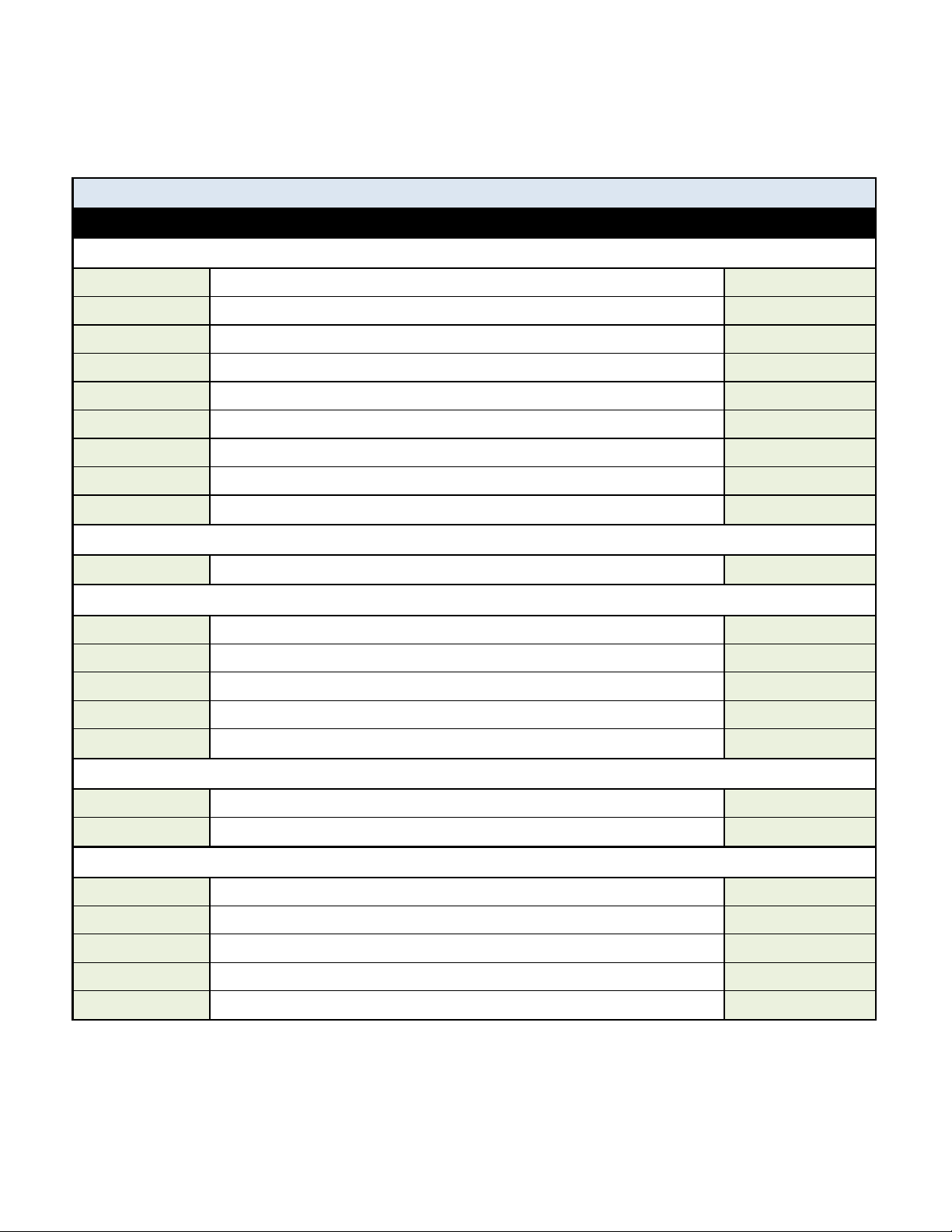
Chart 4: PARTS LIST— 6600
HH-6600 V-HULL STRAIGHT FRAME
Part Description Expected Qty
TANK ASSEMBLY
HH-3000 TANK- HARBORHOIST GEN 1.5 6
HH-2650 KIT BOX, HARBORHOIST GEN 1 MOD TANK SET 3
HH-2601 TOP PLATE - HH GEN 1 MOD- ALUMINUM 6
HH-LPL-1024 GASKET - TOP HARBORHOIST 6
HH-LPL-1028 GASKET - UNDERNEATH - HARBORHOIST 12
HH-LPL-1027 GASKET - BOTTOM - HARBORHOIST 12
HH-LPL-1026 BEAM STRAP - ALUMINUM - HARBOR HOIST 12
HH-LPL-1040 CHANNEL - SUPPORT HH - ALUMINUM 12
HH-LPL-1025 STRAP PLATE - ALUMINUM HARBORHOIST 12
CROSS BEAM
HH-LPL-1018 I BEAM - 84 IN. - 8800 HH 6
WALKWAY
HH-1428 WALKWAY PANEL - HARBORHOIST G1.5 29
HH-2515 SUPPORT-WALKWAY HARBORHOIST 6
HH-LPL-1034 BEAM - 48IN SPAN - ALUM. HH. 4
HH-LPL-1033 TUBE - SPACER, 3X3 ALUMINUM 4
HH-2525 END CAP- HH WALKWAY WITH DECAL 4
HULL PADS
1035105 ASSY HYH HARBORHOIST ALUM BUNK - 16FT 2
1035195 HARDWARE KIT - HARBORHOIST HILL PADS (1 PER TANK SET) 3
CONTROL
HH-2740X CONTROL - HARBORHOIST GEN 1.5 4V EXTERNAL SENSOR 1
HH-2517 CONTROL STAND HARBORHOIST GEN 1.5 1
HHE-2655 KIT, HARDWARE, CONTROL HARDWARE HH 2018 1
3072510 HOSE - RUBBER 1-1/4 in. ID X 75 ft. - CUT 1
HH-2687 KIT, HARDWARE HOSE CLAMPS AND TEES, 6600 1

8
Rev. 04022020
Chart 4: PARTS LIST— 8800
HH-8800 V-HULL STRAIGHT FRAME
Part Description Expected Qty
TANK ASSEMBLY
HH-3000 TANK- HARBORHOIST GEN 1.5 8
HH-2650 KIT BOX, HARBORHOIST GEN 1 MOD TANK SET 4
HH-2601 TOP PLATE - HH GEN 1 MOD- ALUMINUM 8
HH-LPL-1024 GASKET - TOP HARBORHOIST 8
HH-LPL-1028 GASKET - UNDERNEATH - HARBORHOIST 16
HH-LPL-1027 GASKET - BOTTOM - HARBORHOIST 16
HH-LPL-1026 BEAM STRAP - ALUMINUM - HARBOR HOIST 16
HH-LPL-1040 CHANNEL - SUPPORT HH - ALUMINUM 16
HH-LPL-1025 STRAP PLATE - ALUMINUM HARBORHOIST 16
CROSS BEAM
HH-LPL-1018 I BEAM - 84 IN. - 8800 HH 8
WALKWAY
HH-1428 WALKWAY PANEL - HARBORHOIST G1.5 39
HH-2515 SUPPORT-WALKWAY HARBORHOIST 8
HH-LPL-1034 BEAM - 48IN SPAN - ALUM. HH. 6
HH-LPL-1033 TUBE - SPACER, 3X3 ALUMINUM 4
HH-2525 END CAP- HH WALKWAY WITH DECAL 4
HULL PADS
1035106 ASSY HYH HARBORHOIST ALUM BUNK - 20FT 2
1035195 HARDWARE KIT - HARBORHOISTHULL PADS (1 PER TANK SET) 4
CONTROL
HH-2740X CONTROL - HARBORHOIST GEN 1.5 4V EXTERNAL SENSOR 1
HH-2517 CONTROL STAND HARBORHOIST GEN 1.5 1
HHE-2655 KIT, HARDWARE, CONTROL HARDWARE HH 2018 1
3072517 HOSE - RUBBER 1-1/4 in. ID X 100 ft. - CUT 1
HH-2685 KIT, HARDWARE HOSE CLAMPS AND TEES, 8800 1

9
Rev. 04082020
STEP 1: WALKWAY TOP PLATE ASSEMBLY
1. Align the mounng holes for the Top Plate and Top Gasket.
2. Run the Bolts and Liing Ring through the Top Plate and Top Gasket. Fasten with washers as illustrated below.
Bolt 3/8-16x3x5
Flat Washer 1/4” (x8)
Brass Hex Nut 1/2-13
Lock Washer 1/2” 18-8 SS
Liing Ring 1.5 x 4 SS
Nyloc Nut 1/4-20 SS (x4)
Top Gasket
Top Plate
Flat Washer 1/4”
Part # Hardware Required
HH-LPL-1502 Nyloc Nut (1/4-20 SS)
HH-LPL-1501 Hex Bolt (1/4-20 x 1.5 SS)
2090216 Flat Washer (1/4” SS)
HH-1916 Lock Washer 1/2” 18-8 SS
HH-1926 Hex Nut 1/2-13 Brass
HH-2602 Liing Ring 1.5 x 4 SS
Part # Parts Required (Per Tank)
HH-2601 Top Plate
HH-LPL-1024 Top Gasket
Use Kit Box: #HH-2650

10
Rev. 04022020
STEP 2: ATTACH TOP PLATE ASSEMBLY TO STRAP PLATES
1. Align the Walkway Assembly with a Strap Plate.
2. Put U-Bolts through the Strap Plate and into the Walkway assembly, loosely fastening as illustrated.
3. Repeat the process for the second Strap Plate.
NOTE: Only hand ghten brass hex nuts on top of the U-Bolts. They will be removed later to assemble the walkway.
Part # Parts Required (Per Tank)
NA Walkway Assembly
HH-LPL-1025 Strap Plate
Part # Hardware Required
HH-LPL-1503 U-Bolt 3/8-16 x 3 x 5
2090242 Flat Washer 3/8”
HH-LPL-1505 Lock Washer 3/8”
HH-2603 Brass Nut 3/8-16
Assembly aid: Aach zip es to the bases of the U-Bolts to keep them in place during installaon. Zip es
are not provided in the kit.
Use Kit Box: #HH-2650
Lock Washer (3/8”) (x8) Brass Hex Nut (3/8-16) (x8) U-Bolt (3/8-16 x 3 x 5) (x4)
Strap Plate (x2) Walkway Assembly

11
Rev. 04082020
STEP 3: ATTACH TANK FRAME BRACKETS TO STRAP PLATES
U-Bolt
Support Channel
Boom Gasket
Nylon Bushing (2)
Flathead Bolt
Aach Zip Ties
Part # Parts Required (Per Tank)
HH-LPL-1040 Channel Support
HH-LPL-1027 Boom Gasket
HH-LPL-1025 Strap Plate
Part # Hardware Required
HH-LPL-1504 U-Bolt (3/8-16 x 3 x 6)
HH-LPL-1006 Flat Head Bolt (5” SS)
HH-LPL-1031 Nylon HH Tank Bushing
H-1926 Hex Nut (1/2-13 Brass)
1. Align the mounng holes for the Channel Support, Strap Plate, and Boom Gasket.
2. Slide the U-Bolts through the boom of the Channel Support
Assembly Aid: Aach Zip Ties to the bases of the U-Bolts to keep them in place during installaon. Zip Ties are
not provided in the kit.
3. Insert the 5” Flat Head Bolt through the Channel Support and the Boom Gasket.
IMPORTANT: Tighten the Nuts against the Nylon Bushing so the Bolts cannot rotate before assembling into the
tank. This will make it easier to assemble the Boom Gasket in Step 4.
Use Kit Box: #HH-2650
Hex Nut
Hex Nut
Strap

12
Rev. 04022020
STEP 4: ATTACH STRAP TANK ASSEMBLY TO TANK
Tank shown on its back
1. Roll the tank onto its back for unobstructed access to the top and boom of the tank, as illustrated below.
2. Place the completed Strap Plate Assembly into the recesses along the front and top of the tank.
The next procedure must be followed in order to prevent damage to the tank. DO NOT force the
assembly together as this could cause the nylon bushing to damage the tank.
3. Install underneath gasket with recesses facing top side of tank. Secure with 1/2” stainless steel at washer and
1/2” brass Nyloc Nut
4. Evenly ghten the Brass Nyloc Nuts so that the assembly pulls together without binding. Hold top side of at
head bolts while ghtening the Nyloc nuts.
Part # Parts Required (Per Tank)
HH-3000 Tank
HH-LPL-1028 Gasket - Underneath Tank
Part # Hardware Required
HH-LPL-1508 Flat Washer (1/2 x2 OD SS)
HH-2100 Brass Nyloc Nut (1/2-13)
Strap Tank Assembly
Gasket Under-
neath Tank
(Boom-Side)
1/2” Nyloc Hex
nut
1/2” SS Flat
washer
Nylon Bushing
Use Kit Box: #HH-2650

13
Rev. 04082020
STEP 5: STUB TUBE INSTALLATION
1. Reposion the tank in the upright posion.
2. Apply thread sealant to the Stub Tube Recommend Sealants: #2 Permatex, 3M 4200, or Permatex with PTFE.
Sealant must have PTFE. See sealant manufacturer applicaon instrucons.
3. Screw the Stub Tube into the tank ng.
4. Apply Thread Sealant to the elbow and screw into Stub Tube ng. You may need to hold the Stub Tube
ng with a pipe wrench to avoid turning it while screwing in the elbow. As the threads ghten, pay aen-
on to the direcon that the elbow /hose is poinng.
• Oen, the li’s hull pad dra is shallower than that of the vessel. To increase the dra capability of
the li, the Stub Tube may need to be trimmed. See Chart 6 for trimming the Stub Tube and Chart 7
for spacing hull pads. In combinaon, these will give you the dra of the li needed for your vessel.
• Be careful not to overshoot the desired alignment since backing o the Stub Tube can cause a leak
path around the ng. The Stub Tube can be hand ghtened such that minimal threads on the el-
bow are visible.
REPEAT STEPS 1-5 FOR EACH TANK BEFORE PROCEEDING TO STEP 6.
Part # Parts Required (Per Tank)
AIR-00-0215 Stub Tube Assembly
Part # Hardware Required
Not Supplied Thread Sealant
Stub Tube Assembly in Tank
Stub Tube Stub Tube Elbow
Use Kit Box: #HH-2650
Chart 6: STUB TUBE MAXIMUM TRIM PER TANK SET
Forward Front to Rear (in.) A
Model Lis SET 1 SET 2 SET 3 SET 4 SET 5
4400 03"
6600 01.5" 3"
8800 01" 2" 3"
Tanks sets are numbered from front to rear. Set 1 is the farthest forward.

14
Rev. 04022020
STEP 6(a): ALIGNING THE TANKS
Side Alignment
1. Align the tanks next to each other, on each side, spacing them so the mooring rings are 68.25” apart 6600 and
8800 models and 104.68” on the 4400. You may want to use the full-length hull pad as a straight-edge to align
the tanks. The hull pad is used in a later step.
2. Align tanks opposite each other using the rules for minimum beam of li or beam of boat. See Step 6(b) for proper
alignment. Verify the tanks are separated enough to accommodate the cross channel in STEP 6(c).
The minimum beam of the li is calculated by adding 34IN. to the beam of the boat. If the li uses AUX
tanks, the minimum beam of the li is determined by the width of the AUX tank. Refer to Table 1.
When sizing the li this way, it will leave a minimum of a 4IN. gap between the boat and the walkway on each
side. (See gure above) Dock fenders are recommended to prevent the li from catching on the edge of the
dock while raising or lowering. See Chart 1 for minimum li widths.
4” 4”
Beam of Li
AUX Tank Width
68.25” 68.25” 68.25”
6600 Overall Length
8800 Overall Length
4400 Overall Length
(104.68” on 4400)

15
Rev. 04082020
STEP 6(b): TANK AND WALKWAY ALIGNMENT AND ATTACHMENT
1. Place the Spacer Tubes between the outside set of U-Bolts on rst and last tank sets. See Figure B below.
2. Place Span Beams between the U-Bolt sets on the connecng tanks. See Figure C below.
3. Starng with the center tank set (tank set 2 or 3 on 8800), loosely aach the walkway support on top of the span
beam, as illustrated below. Ensure the U-Bolts are centered in the middle of the walkway slots on the walkway
support. As walkway supports are added to the other tank sets, the U-Bolts will shi outward in the walkway
slots. Add walkway supports from the inner tanks sets to the outer ones with a spacing of 1.75”. Thus working
from the middle out. See Figure A.
4. Conrm the Span Beams are centered between the two tanks and the Spacers are in the proper posion. Wait to
ghten all hardware on the walkway unl you have completed Step 6(c).
If you use a Single-Sided Tie-O method for mooring, the Spacer Tubes may be removed in a later step. Do not
ghten the U-Bolts fastening the walkway over the spacers. Refer to STEP 15: TIE-OFF MOORING.
Span Beam installed between U-Bolts on connecng
Walkway Sup- Walkway Slots
Figure C: Span
Spacer Tube installed between the outside
set of U-Bolts on front and rear tank sets
Figure B: Spacer Tube
Brass Nut 3/8”
Lock Washer 3/8”
Flat Washer 3/8”
Part # Parts Required (Per Tank Set)
HH-LPL-1033 Aluminum Spacer Tube (3 X 3)
HH-LPL-1034 Beam - 48in Span—Alum. HH.
HH - 2515* Walkway Support
Part # Hardware Required (Per Tank Set)
HH-LPL-1505 Lock Washer (3/8” SS)
HH-1975 Brass Nut (3/8-16)
2090242 Flat Washer (3/8” SS)
Use Kit Box: #HH-2650
* Part# will depend on model of li. See Chart 4
Figure A: Tank Walkway connecng

16
Rev. 04022020
STEP 6(c): INSTALL TANK CROSS BEAM ASSEMBLY
Part # Parts Required (Per Tank)
HH-LPL-1026 BEAM STRAP—ALUMINUM –HARBORHOIST
HH-LPL-1018* CROSS CHANNEL - I BEAM 84 inch
Part # Hardware Required (Per Tank)
HH-1975 BRASS HEX NUT 3/8-16
2090242 FLAT WASHER 3/8” SS
HH-LPL-1505 LOCK WASHER 3/8-16 SS
HH-LPL-1508 WASHER - FLAT-1/2" x 2 OC SS
1. Connect the facing tanks by placing the Cross Channels on top of the Support Channels between the U-
Bolts. Install the Beam Strap to the tank frame assemblies.
2. Finger-ghten the U-Bolt nuts to hold the Beam Strap in place. Repeat for each set of tanks.
Do not fully ghten unl you verify that Step 6(a), 6(b), and 6(c) have been completed.
THE CROSS CHANNEL END SHOULD HAVE AT LEAST 2 INCHES OF CHANNEL VISIBLE BEFORE GOING UNDER
THE BEAM STRAP
Support Channel
Beam Strap 3/8-16 Brass Hex Nut
3/8” SS Flat Washer
3/8” SS Lock Washer
I Beam Cross Channel *
End of Cross Channel (2” visible minimum)
Use Kit Box: #HH-2650
* Part# will depend on model of li.

17
Rev. 04082020
3. Perform Steps 6(b) and (c). Verify equal length diagonals as you build from tank Set 1 to tank the tank set.
as shown below to ensure they are square.
4. Aer conrming the li is square and all assembly for Steps 6(b) and (c) are completed, ghten all
hardware completely.
Set 1 Set 2 Set 1 Set 2 Set 3
Set 1 Set 2 Set 3 Set 4 Set 1 Set 2 Set 3 Set 4 Set 5

18
Rev. 04022020
STEP 7(a): HULL PAD ALIGNMENT (V-HULL ONLY) - Straight Cross Beam
Before installing the hull pads, it is important to determine the bunk spacing: how far apart the hull pads should be
mounted on the cross beams. To calculate the proper spacing, refer to the table below. Consult your boat manufactur-
er for dead rise informaon.
How to Use the Bunk Value Table
The chart shows pad separaon and max dead rise angle to maintain 1” minimum clearance to the cross channel
listed top to boom.
Aligning the Hull Pads
Place the hull pads as wide as possible while maintaining clearance between the hull and cross beam. Be sure to
check the boat, boat trailer, or consult the boat manufacturer to ensure the locaon is clear of underwater obstruc-
ons, such as speedometer sensors, water pickups, ns, etc. The hull pads can be placed on the li so that the front
is narrower than the rear if needed. If you do this, verify that the hull pad does not cross a stake or other feature on
the hull that would result in a concentrated loading condion. The chart below is based on the dead rise angle and
separaon distance and is provided as a starng point only.
IF YOUR VESSELS DEADRISE FALLS IN BETWEEN TWO NUMBERS IN THE CHART. ALWAYS, MOVE TO THE
NARROWER HULL PAD SEPARATION FOR HULL PAD PLACEMENT.
Table 7(a): Maximum Deadrise
Straight
Cross Beam
Hull Bunks
Hull Pad Max Min
Separation Dead Rise Clearance
(In) (Deg) (In)
12 46.2 1
15 39.6 1
17 36 1
20 31.6 1
25 26.4 1
30 22.8 1
32 21.6 1
35 20 1
40 17.9 1

19
Rev. 04082020
1. Aer conrming the proper spacing, place the Hull Support Bracket for a Hull Pad to the I-Beam. Hold it
in place with an 18” bar clamp.
2. Mount the Hull Support Bracket to the I-Beam using the U-Bolts, Lock Washers, and Brass Nuts. Drill a
7/16" hole through the Hull Support Bracket to connect the U-Bolts to the Cross Channel.
3. Center the Hull Pad from bow to stern.
4. When placing the Hull Pad, rest it on the Cross Channel against the Hull support bracket. Secure it with an 18”
bar clamp.
5. Drill a 7/16” hole through the Hull Pad under the internal web, and then fasten it to the Hull Support
Bracket using the 4” bolt, a at washer, lock washer, and brass nut.
6. Repeat these steps for the opposite side Hull Pad.
STEP 7(b): MOUNTING THE HULL PADS (V-HULL ONLY)
Part # Parts Required
1035104* ASSY HYH HARBORHOIST ALUM BUNK -
12FT.
1035105* ASSY HYH HARBORHOIST ALUM BUNK -
16FT
1035106* ASSY HYH HARBORHOIST ALUM BUNK -
20FT
Part # Hardware Required
HH-2603 NUT 3/8"-16 BRASS
2090242 WASHER - FLAT-3/8" SS
HH-LPL-1505 LOCK WASHER 3/8"-16 SS
HH-LPL-1503 U-BOLT - .375x3x5 SS
Hull Pad*
Full Length Hull
Support Bracket
U-Bolt .375 x 3 x 5
Washer-FLT 3/8”
Lock Washer 3/8”
Nut 3/8”-16
Use Kit Box: 1035195
* See Chart 4 for the Hull Pad used for each model of li.

20
Rev. 04022020
1. Select a mounng locaon on the li walkway. We recommend mounng between two tanks, near the center of
the walkway, to keep it as level as possible.
2. Posion the stand at the desired locaon on the walkway. Run the Carriage Bolts through the Control Stand mount
and down through the holes in the walkway support. Tighten with the supplied hardware. If the control stand is
not level use the supplied at washers as shims to make level.
STEP 8: INSTALLING THE CONTROL STAND
3. Aach the Control Unit to the Control Stand.
Control Unit
Control Stand
Control Stand Mount
Part # Hardware Required
HH-1913 BOLT-CARRIAGE 1/2"-13 X 1.5 SS
HH-1916 WASHER-LOCK 1/2" 18-8 SS
2090208 WASHER-FLAT 1/2" SS
HH-1926 NUT-HEX 1/2 -13 BRASS
Part # Parts Required
HH-2517 CONTROL-STAND HARBORHOIST GEN 1.5
Part # Hardware Required
HH-2603 BOLT -1/4"-20 x 1" SS
2090242 WASHER LOCK 1/4" SS
Use Kit Box: #HHE-2655
Use Kit Box: HHE-2655
Part # Parts Required
HH-2740X CONTROL - HARBORHOIST
GEN 1.5 4V EXTERNAL SENSOR
This manual suits for next models
2
Table of contents
Other HydroHoist Boating Equipment manuals
Popular Boating Equipment manuals by other brands

Floe
Floe V-2000 Assembly instructions

Ultraflex
Ultraflex UC 128-TS Installation and maintenance manual

ARG
ARG ARG65T installation manual

Nielsen-Kellerman
Nielsen-Kellerman SpeedCoach XL1 Troubleshooting

Vetus
Vetus BPAS Wiring diagram

Creek Company
Creek Company Outdoor Discovery Craft ODC 420 quick start guide