HYDROSCAND H16P User manual

USER MANUAL
Edition II - 2017-05-18
Serial number:
H16P

2
H16P USER MANUAL EDITION II 2017-05-18
Hydroscand was established 1969 in Stockholm, Sweden, by Björn Holmström.
The focus was, and still is, uid connectors, hoses and ttings.
About 30 years ago, Hydroscand started developing and manufacturing machines for its own
purpose. High quality and reliable performance in a demanding environment was the primary focus.
Downtime and unnecessary service is always more expensive than the small extra cost of a quality
product. That was the philosophy and still is for what became Hydroscand Machine AB in Säter, 20
years ago.
Today Hydroscand Group has a turnover of 190 million Euro and is present in many countries in
Europe, Asia and Africa. Hydroscand Machine has expanded it´s business to worldwide exports.
No matter where in the world you are, always know that: We stand by our machines.

2
H16P USER MANUAL EDITION II 2017-05-18
CONTENTS
1. INTRODUCTION ............................................. 4
2. SAFETY RULES......................................... 4 - 5
3. EQUIPMENT ............................................. 5 - 7
3.1 WARRANTY ............................................ 5
3.2 IMPORTANT............................................ 6
3.3 IDENTIFICATION ................................ 6 - 7
4. START - UP............................................... 7-10
4.1 MACHINE PLACEMENT............................... 7
4.2 SELECTING DIES...................................... 7
4.3 SETTING CRIMPING MEASURMENTS ............ 8
4.4 CHANGING DIE SET.................................. 9
4.5 CRIMPING.............................................10
5. MAINTENANCE......................................... 10-11
5.1 LUBRICATION ........................................10
5.2 CALIBRATION........................................11
6. TROUBLE SHOOTING......................................11
7. TECHNICAL DATA...........................................12
8. SPARE PARTS ...............................................13

4
H16P USER MANUAL EDITION II 2017-05-18
1. Introduction
This manual provides necessary information for safe use of this machine.
This manual is the result of continual development, testing and technical evalua-
tions that are registered and veried by Hydroscand Machine AB according to
2006:42/EC.
This information is intended only for specialized operators who can operate the
machine without risk to themselves, other persons, property, the machine, or the
environment. The operator should have fundamental knowledge in trouble-shoo-
ting methods, perform machine inspections and simple maintenance according to
the information provided in this manual and according to local legislation for
protection of health and safety.
This manual does not explain disassembly or comprehensive maintenance in de-
tail. These may only be performed by an authorized service technician.
It is necessary to store the manual and keep it in good condition for future use.
Contact your closest authorized supplier for a replacement manual or additional
information if necessary.
This manual should be preserved and stored for the length of the machine’s life-
time or at least ten (10) years in a well-known, easily accessible location together
with other machine documentation.
Hydroscand Machine AB is not liable for injury/damage to persons/machine or
property as a result of improper use, having made prohibited modications to the
machine or misinterpreting this manual’s safety instructions.
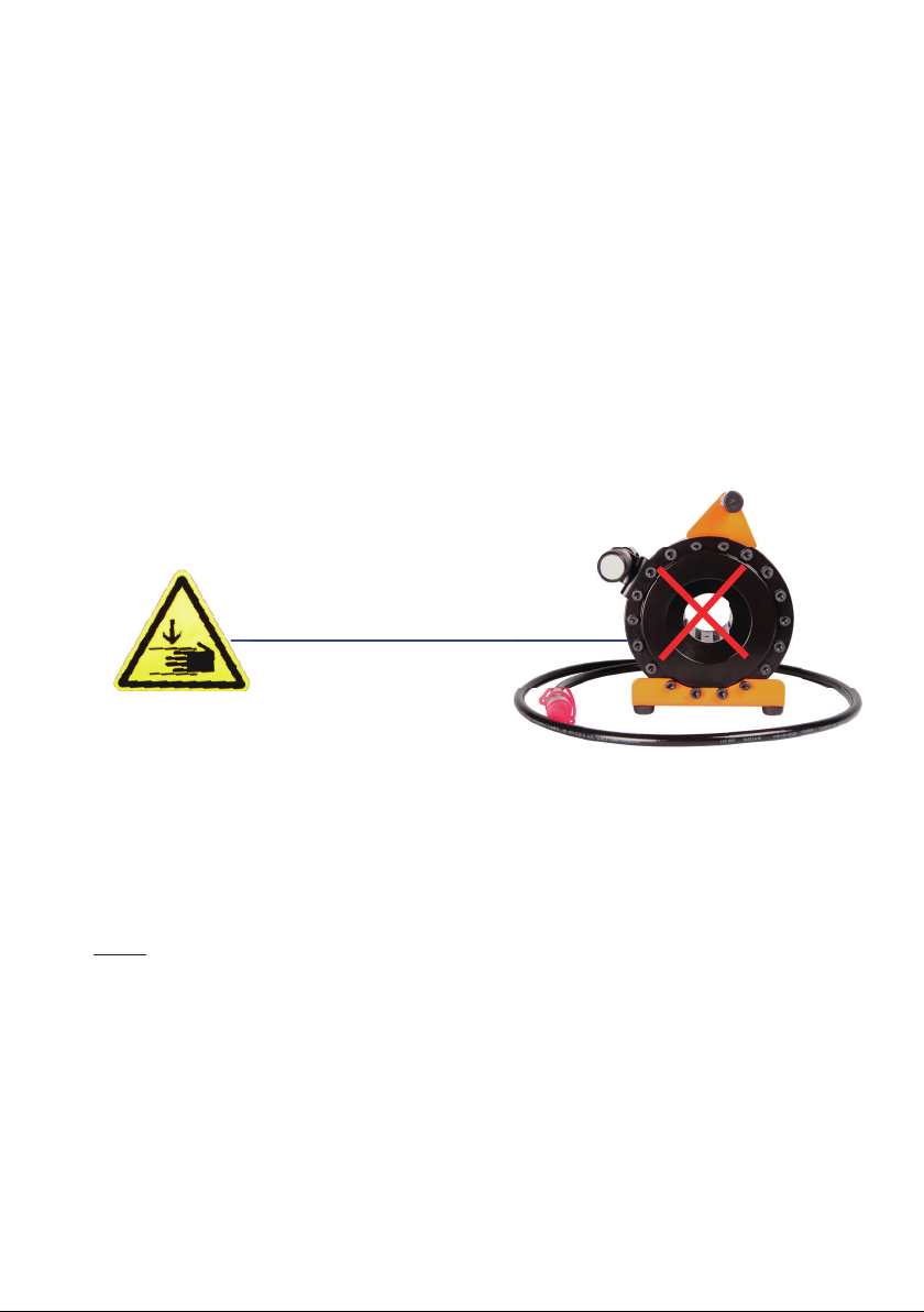
2. Safety rules
Always ensure that the minimum standards for safety, installation and operation are comp-
lied with before operating the machine. Observe the surrounding environmental conditions
such as temperature, humidity, lighting, vibrations, dust and other conditions at the mach-
ine operation site. Never remove the machine’s information or warning plates. Ensure that
they remain clearly readable. Contact an authorized service workshop for replacement plates
if they become unreadable.
The use of any spare parts that deviate from this manual’s specications, any other changes/
manipulations (however insignicant) made to your machine releases Hydroscand Machine
AB from any liability for consequences that arise due to the machine’s performance, level of
safety for nearby persons and/or personal property.

5
H16P USER MANUAL EDITION II 2017-05-18
Disassembling or side-stepping safety devices or rules is extremely hazar-
dous and absolutely prohibited. Refusal to follow these requirements puts
others at severe risk of injury!
Always dispose of operation waste according to current local laws and regula-
tions.
Note!
All maintenance not described in this manual must be performed by an authorized
service technician.
3. Equipment
H16P is a portable, manual crimping machine for hydraulic hose intended for use
in service vehicles. The machine is designed for smaller hose crimping series and
not intended for large-scale production.
The machine consists of a chassis, crimping head and is delivered ready to use,
packed in a wooden box on a pallet.
Note!
Always dispose of operation waste according to current local laws and regula-
tions.
The machine is delivered with:
• Quick connectors and hydraulic hose 2m • Grease tube
• Manual (See separate manual for the pump)
• Certication of compliance according to CE requirements
3.1 Warranty
The warranty lasts one (1) year from purchase and only under the strict condition
that the manual instructions have been followed. The warranty covers defected
material/parts and awed workmanship, replacing defected parts cost.
The warranty does not cover improper use or normal wear. Travel costs, time for
repair and shipping costs are not covered by the warranty. Repairs under the war-
ranty are to be made only by Hydroscand Machine AB or an authorized service
technician approved by Hydroscand Machine AB. Lost income or extra costs that
may arise for any reason are not covered by the warranty.
Note!
Ensure that the machine is undamaged and that all of the described items are
present upon arrival or shortly after. Hydroscand Machine is not liable for incor-
rect or missing parts that are not reported within eight (8) days after delivery.

6
H16P USER MANUAL EDITION II 2017-05-18
3.2 Important
H16P is designed, manufactured and made safe for crimping hydraulic hose in
dimensions 3/16”-1”. Any other use of this machine is considered improper and
Hydroscand Machine AB is not liable for injury or damage to persons, property or
the machine. The machine shall only be used for crimping hydraulic hose accor-
ding to speci cation. Hydroscand Machine AB’s instructions for operating condi-
tions and limitations for use/operation as well as health and safety regulations
must be complied with.
Warning !
Pinch point!
Keep hands and all other body parts away
from the red-indicated area while crimping.
3.3 Identifi cation
The machine can be identi ed by the CE-label with the following information
located on its backside:
• Manufacturer • Serial number • Manufactured year • Weight
Note!
It is absolutely prohibited to remove or damage the identi cation plate. Contact
an authorized service workshop for new plats if they become damaged and
unreadable.
Always provide the following information and technical explanation of the
machine’s problem when contacting the authorized service workshop.

7
H16P USER MANUAL EDITION II 2017-05-18
H16P
1. Crimp diameter adjusting knob
2. Dies
3. Hydraulic connection for high pressure
1. Crimp diameter adjusting knob
3. Hydraulic connection for high pressure
1
32
4. Start-up
4.1 Machine placement
Place the machine on a stable and at surface.
4.2 Selecting dies
Determine the crimping dimensions for the current operation and select the die set with the
correct interval that corresponds to the crimping measurement.
For example: A crimping measurement of 17 mm requires the die set size nr 16 (since it covers
the 16-19 mm interval).
Always select the die set within the correct interval to achieve the best crimping results.
Every die is marked with the smallest crimping measurement in the interval.
Note!
Crimping any measurements outside the table crimping measurement interval is not recom-
mended. Using dies that are too small risk the ferrule becoming oval.

8
H16P USER MANUAL EDITION II 2017-05-18
4.3 Setting crimping measurements
With the machine is a die set table packed that indicates the correct crimping measurement
interval for every die set. Crimping measurements that lie outside of the interval are not
recommended.
Turn the adjusting knob so that the zero (0) on the dial is lined-up with the zero (0) on the
scale. If zero (0) is set, the machine will crimp the smallest diameter provided in the
interval. Every revolution of the knob increases the value on the scale with one unit. One
turn clock-wise corresponds to 0.1 mm on the crimping measurement. The measurement
shall be added to the least-specied diameter in the interval.
Die set Crimping area
16-10
16-12
16-14
16-16
16-19
16-23
16-27
16-31
Base Die
10-12 mm
12-14 mm
14-16 mm
16-19 mm
19-23 mm
23-27 mm
27-31 mm
31-36 mm
39-45 mm
H16 DIES
1 Die size marking
2. Die set pin
2
1
For example: Crimping 16 mm hose requires die nr 16 with the adjusting knob set to zero (0)
and lined up with zero (0) in the window. Crimping 22,2 mm hose recommends die nr 19 with
the adjusting knob turned 3 (three) clock-wise rotations until 3 (three) on the scale and the
2 (two) on the dial is lined up with the zero (0) line on the scale.
The set crimping measurement values can differ slightly from the actual crimping
measurement because the machine’s die expansion and retraction. Compensate this by ad-
justing the setting.
Adjusting knob dial
Control Knob
Scale

9
H16P USER MANUAL EDITION II 2017-05-18
4.4 Changing die sets
1. Retract the dies completely by turning the return valve one turn.
2. Remove the die set by turning it in either direction or pulling it straight out
(radially).
3. Ensure that the 8-segment die set is clean, undamaged and that all are marked
with the same number.
4. With the die marking numbers facing you, insert each die clicking the die pins in
their holes in the crimping head.
5. Ensure that all dies are correctly inserted in the machine.
0
0
2
1
3
5
7
4
6
8
0
2
3
5
7
4
6
8
1
2
4
6
8
3
5
7
0
2
3
5
7
4
6
8
0
33
5
7
4
6
8
0
4
3
5
76
8
0
5
3
76
8
0
6
8
0
7
16-10 10 11 12 10 10 10 10 10
0 turn 1 turn 2 turns 3 turns 4 turns 5 turns 6 turns 7 turns
16-12 12 13 14 12 12 12 12 12
16-14 14 15 16 14 14 14 14 14
16-16 16 17 18 19 16 16 16 16
16-19 19 20 21 22 23 19 19 19
16-23 23 24 25 26 27 23 23 23
16-27 27 28 29 30 31 27 27 27
16-31 31 32 33 34 35 36 37 38
39 40 41 42 43 44 45 46Masterdies
USE
NEXT
SIZE!
DIE SET

10
H16P USER MANUAL EDITION II 2017-05-18
4.5 Crimping
1. When the die set is inserted in the machine and the crimping measurement set,
place the hose/pipe application between the dies. Ensure that all dies are
correctly inserted in the machine.
2. The crimping diameter is reached when the indication lamp lights.
See below photo.
3. Make sure that the crimping was correct and make adjustments if necessary.
5. Maintenance
5.1 Lubrication
The machine should be cleaned and lubricated every eight (8) operation hours. Retract the
dies to lubricate. Use a small brush to lubricate the cone shaped surfaces in the cylinder.
Better to lubricate sparingly and more often than seldom and excessively. Without lubrica-
tion, the machine looses power and you will damage the sliding surfaces.
Use only the lubrication recommended by Hydroscand Machine AB: Optimol viscogen 4.

11
H16P USER MANUAL EDITION II 2017-05-18
5.2 Calibration
If the actual crimping measurement differs too much from the set crimping measurements
then calibrate the machine. Use die set nr 19.
1. Set the dial to 0.0.
2. Crimp. The crimping diameter is reached when the the indication lamp lights.
Check the crimping measurement.
4. Loosen the adjustment knob (2). Turn the adjustment knob.
For example: Measurement is 18.8. Adjustment dial turns - 0,2 to achieve
crimping measurement nr 19.
6. Calibration is complete.
7. Check. Repeat the procedure if the actual crimping measurement differs from the
set crimping measurement.
6. Trouble shooting
Problem
Crimping measurement is incon-
sistent:
Low crimping force:
2. Insufcient lubrication.
3. Adjusting knob lost its
position.
1. Insufcient lubrication.
2. Return valve not
closed.
3. Leakage.
4. Pump leakage.
Lubricate.
Calibrate.
Lubricate.
Close the valve.
Repair.
Replace seals.
Reason Solution
(2)

TECHNICAL DATA
Crimping range in mm........................................ 10 - 45
Crimping range in inch ................................0,39 - 1,77
Crimping force in metric tons .................................95,5
Crimping force in kN...............................................955
Maximum hose size in inches.......................... 3/16” - 1”
Die set.................................................................H 16
Maximum travel of dies in mm .............................20 mm
Master die Diam. /Lenght in mm .........................39 / 64
Master die Diam. /Lenght in inch.................. 1,54 / 2,52
Machine control ............................................... Manual
Max pressure ................................................... 630 bar
Colour................................................... Black / Orange
DIMENSIONS
Depth/Width/Height .......................... 180x230x270 mm
Weight H16P....................................................... 20 kg
DESIGNATION: PART NUMBER:
H16P .........................................................9028-00-61
Handpump H16P, 630Bar ............................9028-02-08E
DIES: PART NUMBER:
H16-10 .......................................................9070-16-10
H16-12 .......................................................9070-16-12
H16-14 .......................................................9070-16-14
H16-16 .......................................................9070-16-16
H16-19 .......................................................9070-16-19
H16-23 ...................................................... 9070-16-23
H16-27 ...................................................... 9070-16-27
H16-31 .......................................................9070-16-31

13
H16P USER MANUAL EDITION II 2017-05-18
1
23
13
22
21
16
15
16
15
17
18
15
869207
19
4
11
10
12 3
2
5
14
12
Part number:
RAL 2003S-90280061
RAL 9023-90280095
Pos.
Artikelnummer
Part number
Ritningsnummer
Drawing number
Description
Antal
Qty
1 90270028
S053041
Crimping head assy
1
2
90270260/
90270789
D053051 Base plate RAL2003/
Base plate RAL9023
1
3 90270262
D053054
Set screw bracket
1
4 90270569
SC MC6SPB
M8 10x45
1
5 90010423
T0105
Rubber foot
4
6 90270222
D055061
Handle zinc plated
1
7 90175252
M12
ML6M 12-8-fzb ISO 4035
1
8 90180314
T0325_22_120
Handle
1
9
90270261/
90270790
D053052
Handle bracket RAL2003/
Handle bracket RAL9023
1
10 90270899
S053057
LED-Buzzer
1
11 90270272
S053046
Bracket assy 1
12 90270275
S053047
Set screw H16P
1
13 90270270
7002-04-06
Adapter
1
14 90175222
SC MK6S
M5 x 10
4
15 90175020
Wa BRB
M8
8
16 90270038
SC MC6S
M8 x 40 12.9
6
17 90175325
SC MC6S
M8 x 35 12.9
10
18 90175007
SC MC6S
M8 x 20
2
19 90175027
SC MC6S
M6 x 20
2
20 90175090
Wa FBB
12,5x24x2
1
21 90270317
5C101156202
Snabbkoppling
1
22 90270752
Tredo
1/4"
1
23 90270753
Tredo
3/8"
1
1
Over all updated
2015-02-11
2
New version LED module
2015-05-11
3
Added parts
2016-03-07
QTY.
Material
Date
PART LIST
Part name
Drw. No.
Scale
Drawn by
Approved by
Drawing size
Rev. No.
Revision information
Checked date
Serialno.
Rev.
Dimension
1:3
A3
For messures without
tolerances ISO 2768-m
is applied.
General surface finish
is: ra 3,2
Sharp edges broken.
Weight
3
PY
2015-01-20
S053052
H16P with LED indicator

14
H16P USER MANUAL EDITION II 2017-05-18
+
4
5
1
2
3
6
67
+
+
+
Part number: 90270899
LED
Buzzer
3V
+
+
Plus vänds uppåt
Plus facing up
+
Pos.
Artikelnummer
Part number
Ritningsnummer
Drawing number
Benämning
Name
Antal
Qty
1 90270896
D053086
Body
1
2 90270304 90270304
Push Button
1
3 90270898
3mmLED
LED T1
1
4 90270897
Piezo_round
Piezo summer
1
5 90270900
CR1632
Button cell 3V
1
6 90270935
D053087
Spring
2
7 90183463
O-ring
14x2
1
1
New body, O-ring added
2016-09-19
QTY.
Material
Date
PART LIST
Part name
Drw. No.
Scale
Drawn by
Approved by
Drawing size
Rev. No.
Revision information
Checked date
Serialno.
Rev.
Dimension
2:1
A3
For messures without
tolerances ISO 2768-m
is applied.
General surface finish
is: ra 3,2
Sharp edges broken.
Weight
1
PY
2015-05-11
1
S053057
LED-buzzer assy

15
H16P USER MANUAL EDITION II 2017-05-18
1
S053041
QTY. Material Date
PART LIST
Part name
Drw. No.
Scale
Drawn by
Approved by
Drawing size
Rev. No. Revision information Checked date
PS
Dimension
Serialno.
Weight
Rev.
0
A3
2008-12-03
Crimping head H16
Pos. Part number Drawing number Description Qty.
1 90270228 D053040 Cylinder house 1
2 * T0494 O-ring 1
3 * T0495 Support ring 1
4 90270031 D053041 Piston 1
5 90270034 T0491 Return spring outer 6
6 90270035 T0492 Return spring inner 6
7 90270032 D053039 Base die, kit 8
8 90270229 D053042 Cylinder gable 1
9 90175325 ISO 4762 Socket head cap screw 18
10 90270033 T0490 Master die spring 8
11 90270037 T0497 Spring screw 8
12 * T0493 O-ring 1
13 * T0496 Support ring 1
90270036 *Seal Kit
12
B (2 : 1)
13
2
A (2 : 1)
3
Section view
A
B
13
1
5
4
6
9
8
10
11
7
2
3
12

Pungmakarbovägen 1, SE-783 90 Säter, Sweden
Phone: +46-(0)225-573 30 Fax: +46-(0)225-501 08
info@hydroscand-machine.se www.hydroscand-machine.se
Table of contents
Other HYDROSCAND Industrial Equipment manuals
Popular Industrial Equipment manuals by other brands

SMC Networks
SMC Networks LVD Series manual

HEIDENHAIN
HEIDENHAIN ECI 1119 EnDat22 operating instructions

BERTHOLD TECHNOLOGIES
BERTHOLD TECHNOLOGIES LB 8110 operating manual

Veit Brisay
Veit Brisay Fuse Master BX Series Handbook

MGF
MGF S80 SPREADER BEAM user guide

Newport
Newport IDL165-LM Series user manual