Hyundai Heavy Industries Hi4 User manual

1
Hyundai Heavy Industries
Hi4 Robot Driver
1 System Configuration.......................................................................................................3
2 Selection of External Device............................................................................................6
3 Example of Communication Setting.................................................................................7
4 Setup Items....................................................................................................................15
5 Cable Diagram...............................................................................................................20
6 Supported Device...........................................................................................................25
7 Device Code and Address Code....................................................................................27
8 Error Messages..............................................................................................................28

Hi4 Robot Driver
GP-Pro EX Device/PLC Connection Manual 2
Introduction
This manual describes how to connect the Display and the External Device (target PLC).
In this manual, the connection procedure will be described by following the below sections:
1System Configuration
This section shows the types of External
Devices which can be connected and SIO
type.
)"1 System Configuration" (page 3)
2Selection of External Device
Select a model (series) of the External
Device to be connected and connection
method.
)"2 Selection of External Device" (page 6)
3Example of Communication Settings
This section shows setting examples for
communicating between the Display and
the External Device.
)"3 Example of Communication Setting" (page
7)
4Setup Items
This section describes communication
setup items on the Display.
Set communication settings of the Display
with GP-Pro EX or in off-line mode.
)"4 Setup Items" (page 15)
5Cable Diagram
This section shows cables and adapters
for connecting the Display and the
External Device.
)"5 Cable Diagram" (page 20)
Operation

Hi4 Robot Driver
GP-Pro EX Device/PLC Connection Manual 3
1 System Configuration
The system configuration in the case when the External Device of Hyundai Heavy Industries and the Display are
connected is shown.
Connection Configuration
• 1:1 connection
Series CPU Link I/F SIO Type Setting Example Cable Diagram
Hi4 Robot BD412 board
CNSIO port on CPU RS-232C "Setting Example 1"
(page 7) "Cable Diagram 1"
(page 20)
OPSIO port on CPU
RS-232C "Setting Example 2"
(page 9) "Cable Diagram 2"
(page 21)
RS422/485
(4 wire) "Setting Example 3"
(page 12) "Cable Diagram 3"
(page 22)
Display External Device

Hi4 Robot Driver
GP-Pro EX Device/PLC Connection Manual 4
COM Port of IPC
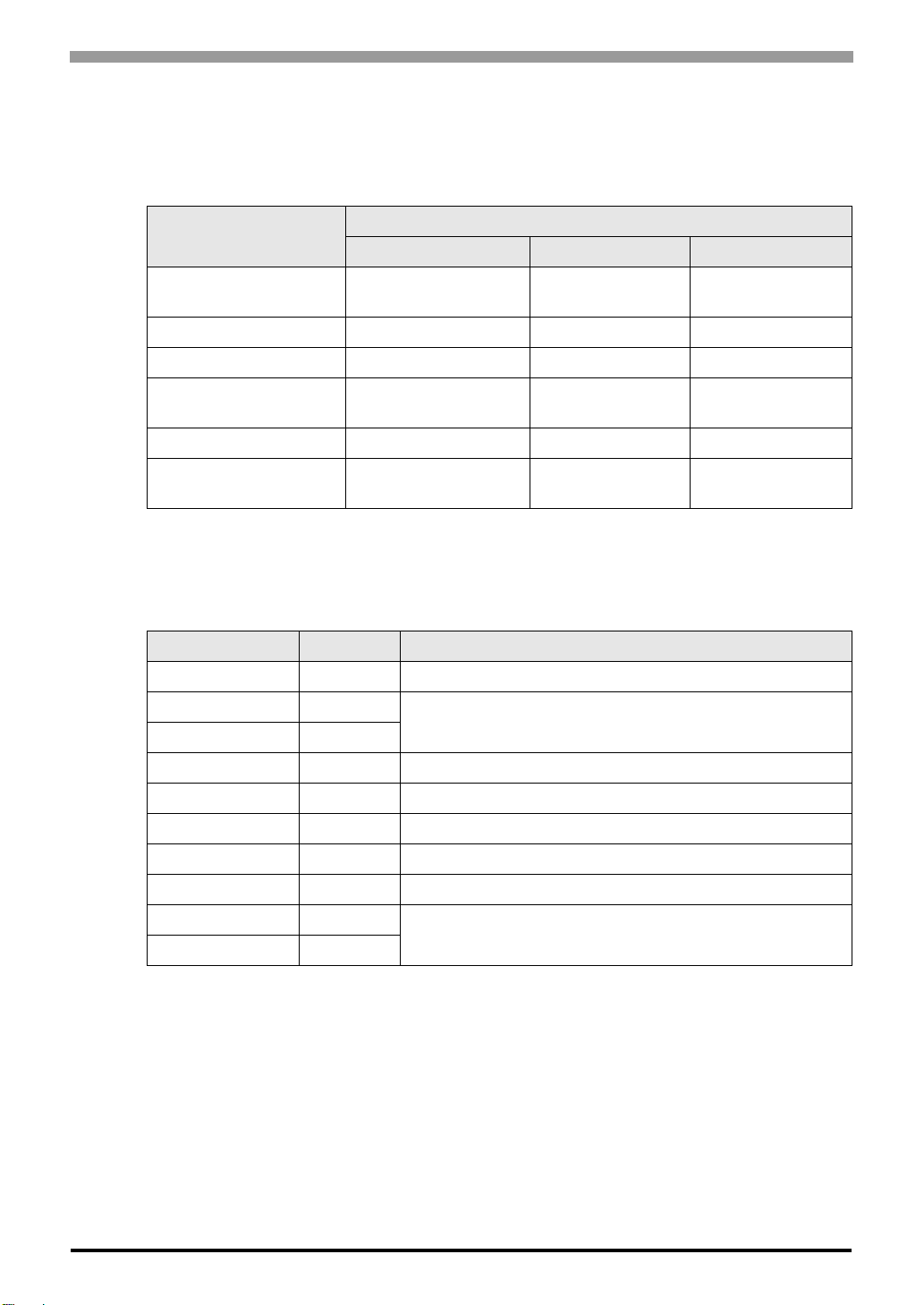
When connecting IPC with External Device, the COM port which can be used changes with series and SIO type.
Please refer to the manual of IPC for details.
Usable port
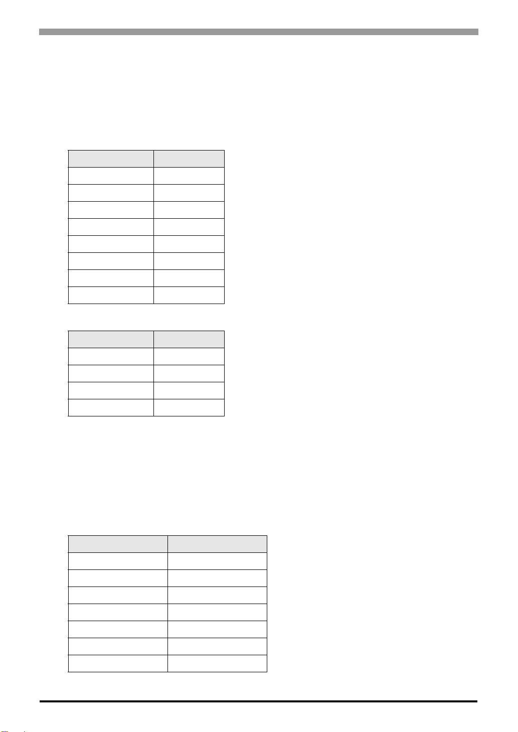
Dip switch setting: RS-232C
Series Usable port
RS-232C RS-422/485(4 wire) RS-422/485(2 wire)
PS-2000B COM1*1 , COM2,
COM3*1, COM4
*1 The RI/5V can be switched. Please switch with the change switch of IPC.
--
PS-3450A, PS-3451A COM1, COM2*1*2 COM2*1*2 COM2*1*2
PS-3650A, PS-3651A COM1*1 --
PS-3700A (Pentium®4-M)
PS-3710A COM1*1, COM2*1,
COM3*2 , COM4
*2 It is necessary to set up the SIO type with the Dip switch. Please set up as follows according to SIO
type to be used.
COM3*2 COM3*2
PS-3711A COM1*1, COM2*2 COM2*2 COM2*2
PL-3000B COM1*1*2, COM2*1,
COM3, COM4 COM1*1*2 COM1*1*2
Dip switch Setting Description
1OFF
*1
*1 It is necessary to turn ON the set value, only when using PS-3450A and PS-3451A.
Reserve (always OFF)
2OFF
SIO type: RS-232C
3OFF
4 OFF Output mode of SD (TXD) data: Always output
5 OFF Terminal resistance (220Ω) insertion to SD (TXD): None
6 OFF Terminal resistance (220Ω) insertion to RD (RXD): None
7 OFF Short-circuit of SDA (TXA) and RDA (RXA): Does not Exist
8 OFF Short-circuit of SDB (TXB) and RDB (RXB): Does not Exist
9OFF
RS (RTS) Auto control mode: Disable
10 OFF

Hi4 Robot Driver
GP-Pro EX Device/PLC Connection Manual 5
Dip switch setting: RS-422/485 (4 wire)
Dip switch setting: RS-422/485 (2 wire)
Dip switch Setting Description
1 OFF Reserve (always OFF)
2ON
SIO type: RS-422/485
3ON
4 OFF Output mode of SD (TXD) data: Always output
5 OFF Terminal resistance (220Ω) insertion to SD (TXD): None
6 OFF Terminal resistance (220Ω) insertion to RD (RXD): None
7 OFF Short-circuit of SDA (TXA) and RDA (RXA): Does not Exist
8 OFF Short-circuit of SDB (TXB) and RDB (RXB): Does not Exist
9OFF
RS (RTS) Auto control mode: Disable
10 OFF
Dip switch Setting Description
1 OFF Reserve (always OFF)
2ON
SIO type: RS-422/485
3ON
4 OFF Output mode of SD (TXD) data: Always output
5 OFF Terminal resistance (220Ω) insertion to SD (TXD): None
6 OFF Terminal resistance (220Ω) insertion to RD (RXD): None
7 ON Short-circuit of SDA (TXA) and RDA (RXA): Exist
8 ON Short-circuit of SDB (TXB) and RDB (RXB): Exist
9ON
RS (RTS) Auto control mode: Enable
10 ON

Hi4 Robot Driver
GP-Pro EX Device/PLC Connection Manual 6
2 Selection of External Device
Select the External Device to be connected to the Display.
Setup Items Setup Description
Maker Select the maker of the External Device to be connected. Select "Hyundai Heavy
Industries".
Series
Select a model (series) of the External Device to be connected and connection method.
Select "Hi4 Robot".
Check the External Device which can be connected in "Hi4 Robot" in system
configuration.
)"1 System Configuration" (page 3)
Use System Area
Check this option when you synchronize the system data area of the Display and the device
(memory) of the External Device. When synchronized, you can use the ladder program of
the External Device to switch the display or display the window on the Display.
Cf. GP-Pro EX Reference Manual "Appendix 1.4 LS Area (only for direct
access method)"
This can be also set with GP-Pro EX or in off-line mode of the Display.
Cf. GP-Pro EX Reference Manual "5.14.6 Setting Guide of [System Setting
Window], Setting Guide of [Main Unit Settings], System Area Setting"
Cf. Maintenance/Troubleshooting manual "2.14.1 Common to the Display",
Setting Guide of [Main Unit Settings], System Area Setting"
Port Select the Display port to be connected to the External Device.

Hi4 Robot Driver
GP-Pro EX Device/PLC Connection Manual 7
3 Example of Communication Setting
The following shows examples of communication settings of the Display and the External Device, which is
recommended by Pro-face.
3.1 Setting Example 1
Settings of GP-Pro EX
Communication Settings
To display the setting screen, select [Device/PLC Settings] from [System setting window] in workspace.
Device Setting
To display the setting screen, click ([Setting]) of External Device you want to set from [Device-Specific
Settings] of [Device/PLC Settings].

Hi4 Robot Driver
GP-Pro EX Device/PLC Connection Manual 8
Settings of External Device
Communication setting of External Device using DIP switches and Teach Pendant of External Device.
Please refer to the manual of the External Device for more details.
DIP Switch Setting
Set the DIP switch for built-in PLC.
Teach Pendant Setting
1Press [PF2].
2Select [2: Controller parameter]-[2: Serial ports]-[3: Serial Port #1(CNSIO)] in order from the displayed menu so
as to display [Serial Port 1].
3Set the setup items as follows.
4Press [PF2].
5Select [2: Controller parameter]-[18: MODBUS environment setting] to displayed [MODBUS setting].
6Set the setup items as follows.
7Press [SET].
DIP switches Settings
SW01 OFF
SW02 OFF
SW03 OFF
SW04 OFF
SW05 ON
SW06 OFF
SW07 OFF
SW08 OFF
Setup Items Setting Value
Baudrate 38400
Character length 8
Stop bit 1
Parity bit Disable
Echo Disable
Port Usage MODBUS
Setup Items Setting Value
Transmission mode RTU
Slave Address 1

Hi4 Robot Driver
GP-Pro EX Device/PLC Connection Manual 9
3.2 Setting Example 2
Settings of GP-Pro EX
Communication Settings
To display the setting screen, select [Device/PLC Settings] from [System setting window] in workspace.
Device Setting
To display the setting screen, click ([Setting]) of External Device you want to set from [Device-Specific
Settings] of [Device/PLC Settings].

Hi4 Robot Driver
GP-Pro EX Device/PLC Connection Manual 10
Settings of External Device
Communication setting of External Device using DIP switches and Teach Pendant of External Device.
Please refer to the manual of the External Device for more details.
DIP Switch Setting
Set DIP switch for built-in PLC and DIP switch for OPSIO port
• DIP switch for built-in PLC
• DIP switch for OPSIO port
Teach Pendant Setting
1Press [PF2].
2Select [2: Controller parameter]-[2: Serial ports]-[3: Serial Port #1 (CNSIO)] in order from the displayed menu so
as to display [Serial Port 1].
3Set anything other than [MODBUS] to [Port Usage].
4Select [4: Serial Port #2 (OPSIO)] in the same procedure so as to display [Serial Port 2].
5Set the setup items as follows.
6Press [PF2].
DIP switches Settings
SW01 OFF
SW02 OFF
SW03 OFF
SW04 OFF
SW05 ON
SW06 OFF
SW07 OFF
SW08 OFF
DIP switch Settings
SW01 ON
SW02 ON
SW03 OFF
SW04 OFF
Setup Items Setting Value
Baudrate 38400
Character length 8
Stop bit 1
Parity bit Disable
Echo Disable
Conv. RS422-RS485 Disable
Port Usage MODBUS

Hi4 Robot Driver
GP-Pro EX Device/PLC Connection Manual 11
7Select [2: Controller parameter]-[18: MODBUS environment setting] to display [MODBUS setting].
8Set the setup items as follows.
9Press [SET].
Setup Items Setting Value
Transmission mode RTU
Slave Address 1

Hi4 Robot Driver
GP-Pro EX Device/PLC Connection Manual 12
3.3 Setting Example 3
Settings of GP-Pro EX
Communication Settings
To display the setting screen, select [Device/PLC Settings] from [System setting window] in workspace.
Device Setting
To display the setting screen, click ([Setting]) of External Device you want to set from [Device-Specific
Settings] of [Device/PLC Settings].

Hi4 Robot Driver
GP-Pro EX Device/PLC Connection Manual 13
Settings of External Device
Communication setting of External Device using DIP switches and Teach Pendant of External Device.
Please refer to the manual of the External Device for more details.
DIP Switch Setting
Set DIP switch for built-in PLC and DIP switch for OPSIO port.
• DIP switch for built-in PLC
• DIP switch for OPSIO port
Teach Pendant Setting
1Press [PF2].
2Select [2: Controller parameter]-[2: Serial ports]-[3: Serial Port #1(CNSIO)] in order from the displayed menu so
as to display [Serial Port 1].
3Set anything other than [MODBUS] to [Port Usage].
4Select [4: Serial Port #2 (OPSIO)] in the same procedure so as to display [Serial Port 2].
5Set the setup items as follows.
6Press [PF2].
DIP switches Settings
SW01 OFF
SW02 OFF
SW03 OFF
SW04 OFF
SW05 ON
SW06 OFF
SW07 OFF
SW08 OFF
DIP switch Settings
SW01 OFF
SW02 OFF
SW03 ON
SW04 ON
Setup Items Setting Value
Baudrate 38400
Character length 8
Stop bit 1
Parity bit Disable
Echo Disable
Conv. RS422-RS485 Disable
Port Usage MODBUS

Hi4 Robot Driver
GP-Pro EX Device/PLC Connection Manual 14
7Select [2: Controller parameter]-[18: MODBUS environment setting] to display [MODBUS setting].
8Set the setup items as follows.
9Press [SET].
Setup Items Setting Value
Transmission mode RTU
Slave Address 1

Hi4 Robot Driver
GP-Pro EX Device/PLC Connection Manual 15
4 Setup Items
Set communication settings of the Display with GP-Pro EX or in off-line mode of the Display.
The setting of each parameter must be identical to that of External Device.
)"3 Example of Communication Setting" (page 7)
4.1 Setup Items in GP-Pro EX
Communication Settings
To display the setting screen, select [Device/PLC Settings] from [System setting window] in workspace.
Setup Items Setup Description
SIO Type Select the SIO type to communicate with the External Device.
Speed Select speed between the External Device and the Display.
Data Length Display data length.
Parity Select how to check parity.
Stop Bit Select stop bit length.
Flow Control Select the communication control method to prevent overflow of transmission and
reception data.
Timeout Use an integer from 1 to 127 to enter the time (s) for which the Display waits for the
response from the External Device.
Retry In case of no response from the External Device, use an integer from 0 to 255 to enter how
many times the Display retransmits the command.
Wait To Send Use an integer from 0 to 255 to enter standby time (ms) for the Display from receiving
packets to transmitting next commands.
RI/VCC You can switch RI/VCC of the 9th pin when you select RS232C for SIO type.
It is necessary to change RI/5V by changeover switch of IPC when connect with IPC.
Please refer to the manual of the IPC for more detail.

Hi4 Robot Driver
GP-Pro EX Device/PLC Connection Manual 16
Device Setting
To display the setting screen, click ([Setting]) of External Device you want to set from [Device-Specific
Settings] of [Device/PLC Settings].
Setup Items Setup Description
Slave Address Use an integer from 1 to 247 to enter the address of the External Device.

Hi4 Robot Driver
GP-Pro EX Device/PLC Connection Manual 17
4.2 Setup Items in Off-Line Mode
Communication Settings
To display the setting screen, touch [Device/PLC Settings] from [Peripheral Settings] in off-line mode. Touch the
External Device you want to set from the displayed list.
• Please refer to Maintenance/Troubleshooting for more information on how to enter off-line
mode or about operation.
Cf. Maintenance/Troubleshooting "2.2 Offline Mode"
Setup Items Setup Description
SIO Type
Select the SIO type to communicate with the External Device.
To make the communication settings correctly, confirm the serial interface specifications of
Display unit for [SIO Type].
We cannot guarantee the operation if a communication type that the serial interface does not
support is specified.
For details concerning the serial interface specifications, refer to the manual for Display
unit.
Speed Select speed between the External Device and the Display.
Data Length Display data length.
Parity Select how to check parity.
Stop Bit Select stop bit length.
Flow Control Select the communication control method to prevent overflow of transmission and reception
data.
Timeout (s) Use an integer from 1 to 127 to enter the time (s) for which the Display waits for the
response from the External Device.
Continues to the next page.

Hi4 Robot Driver
GP-Pro EX Device/PLC Connection Manual 18
Device Settings
To display the setting screen, touch [Device/PLC Settings] from [Peripheral Equipment Settings]. Touch the
External Device you want to set from the displayed list, and touch [Device Settings].
Retry In case of no response from the External Device, use an integer from 0 to 255 to enter how
many times the Display retransmits the command.
Wait To Send (ms) Use an integer from 0 to 255 to enter standby time (ms) for the Display from receiving
packets to transmitting next commands.
Setup Items Setup Description
Device/PLC name Select the External Device to set. Device name is a title of the External Device set with GP-
Pro EX. (Initial value [PLC1])
Slave Address Use an integer from 1 to 247 to enter the address of the External Device.
Setup Items Setup Description

Hi4 Robot Driver
GP-Pro EX Device/PLC Connection Manual 19
Option
To display the setting screen, touch [Device/PLC Settings] from [Peripheral Equipment Settings]. Touch the
External Device you want to set from the displayed list, and touch [Option].
Setup Items Setup Description
RI/VCC Switches RI/VCC of the 9th pin.
It is necessary to change RI/5V by changeover switch of IPC when connect with IPC.
Please refer to the manual of the IPC for more detail.

Hi4 Robot Driver
GP-Pro EX Device/PLC Connection Manual 20
5 Cable Diagram
The cable diagram shown below may be different from the cable diagram recommended by Hyundai Heavy
Industries. Please be assured there is no operational problem in applying the cable diagram shown in this manual.
• The FG pin of the External Device body must be D-class grounded. Please refer to the manual of the External
Device for more details.
• SG and FG are connected inside the Display. When connecting SG to the External Device, design the system
not to form short-circuit loop.
• Connect the isolation unit, when communication is not stabilized under the influence of a noise etc.
Cable Diagram 1
When using your own cable
Display
(Connection Port) Cable Notes
GP (COM1)
LT (COM1)
IPC*1
PC/AT
*1 Only the COM port which can communicate by RS-232C can be used.
)"COM Port of IPC" (page 4)
Your own cable Cable length: 15m or less
Shield
CD
RD(RXD)
SD(TXD)
ER(DTR)
SG
DR(DSR)
RS(RTS)
CS(CTS)
1
2
3
4
5
6
7
8
Signal name
Pin
Display
D-sub 9 pin (socket)
CD
TXD
RXD
DTR
SG
DSR
RTS
CTS
Shell
1
2
3
4
5
6
7
8
Signal name
Pin
External Device
D-sub 9 pin (plug)
Display
Table of contents
Other Hyundai Heavy Industries Robotics manuals