SPECIFICATIONS
TNV Application Manual 1-3
Atmospheric conditions and engine configuration affect the rated output of a TNV engine. TNV engines are
tested using the methods established by the Society of Automotive Engineers (SAE) J1349 and International
Organization for Standardization (ISO) 3046/1. These standards state that engine output (net power rating)
should be determined under the following atmospheric conditions (called the standard conditions). If the
operating environment for your application differs from these standard conditions see Correcting Observed
Power
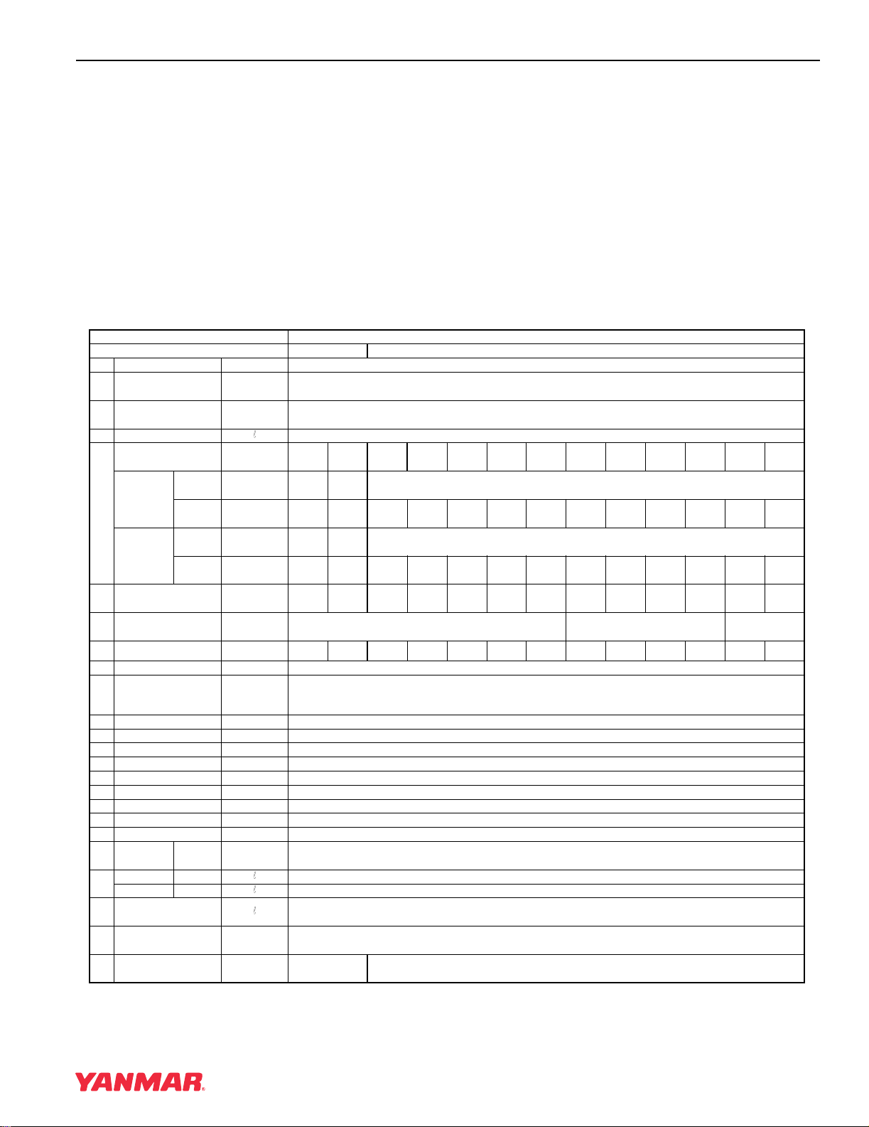
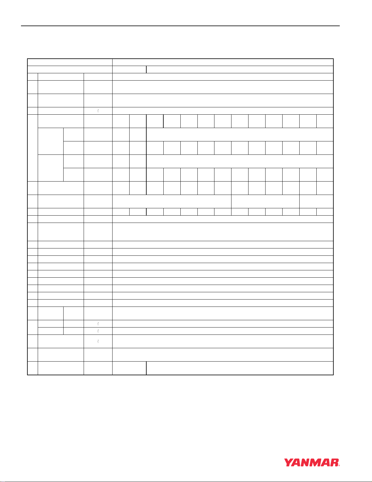
SPECIFICATIONS
DI Series
3TNV82A-B
3TNV82A-Z (Option Electronic Control System)
Note: This table is subject to change for performance improvement.
*1: Gross outputs are theoretical, calculated from cooling fan formula. These are for reference only.
Engine model 3TNV82A-B/3TNV82A-Z
Engine classification CL VM
1 Type — Vertical, 4-cycle water-cooled diesel engine
2Combustion
system — Direct injection (DI)
3No. of cylinders -
Bore ×Stroke
n -
mm ×mm 3 - 82×84
4 Displacement 1.331
5
Rated engine
speed min-1 2200 2300 2400 2500 2600 2700 2800 3000
Output
(Gross) *1
Cont.
rating kW
Rated
output kW 16.5 17.3 18.1 18.9 19.7 20.5 21.3 23.0
Output
(NET)
Cont.
rating kW
Rated
output kW 16.0 16.8 17.5 18.2 19.0 19.7 20.4 21.9
6Maximum idling
speed min-1 ±25 2375 2485 2570 2675 2780 2890 2995 3180
7Specific fuel
consumption g/kWh ≤245 ≤252 ≤258
8 Exhaust gas temp. °C (°F) ≤580 ≤590 ≤600 ≤610 ≤620 ≤630 ≤640 ≤
660
9 Compression ratio — 19.2
10 Diesel fuel injection
pressure
MPa
(kgf/cm2)
11 Main shaft side — Flywheel side
12 Rotation direction — Counterclockwise (Viewed from flywheel side)
13 Governor — Mechanical governor (All-speed governor) / Electronic governor (All-speed governor)
14 Aspiration — Natural aspiration
15 Cooling system — Liquid-Cooled With Radiator
16 Lubricating system — Forced lubrication with multi-stage trochoid pump
17 Starting system — Electric starting
18 Charging system — Alternator (12 VDC/40 A)
19 Starting aid device — Super-quick Heating Glow plug
20 Engine oil
pressure
Rated
speed MPa 0.34±0.05 (3.5±0.5)
21 Oil pan Full 5.5
capacity Useful 1.9
22 Engine coolant
capacity 1.8 (Engine only)
23 Cooling fan type -
dia. ×No. of blades mm Made by resin, Pusher, F Type - φ335(NF)×6
24 Crank V-pulley dia./
Fan V-pulley dia. mm/mm φ120 / φ90 φ110 / φ110
0
+10
19.6 0
+1.0 )(200
00_Electronic_Control_System.book 3 ページ 2006年5月29日 月曜日 午後2時12分