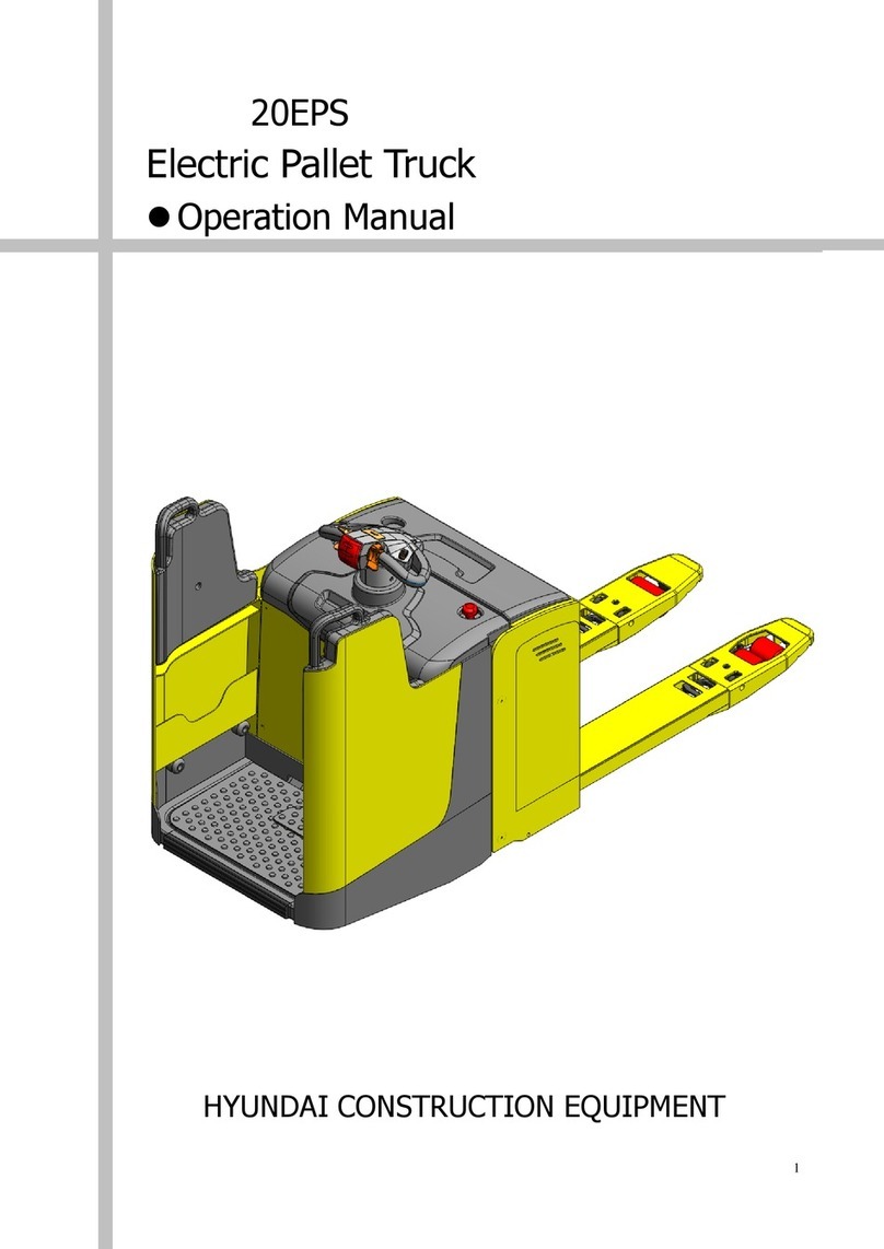
Hyundai 15L 7M User manual

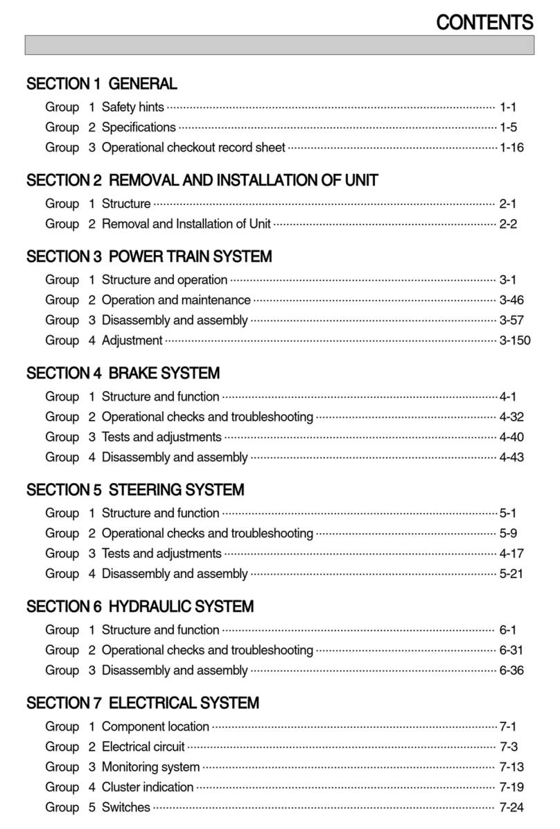
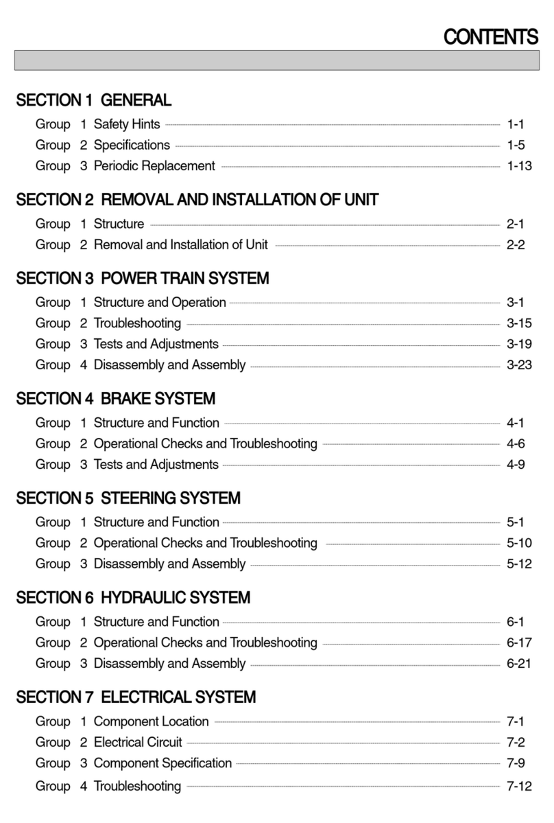
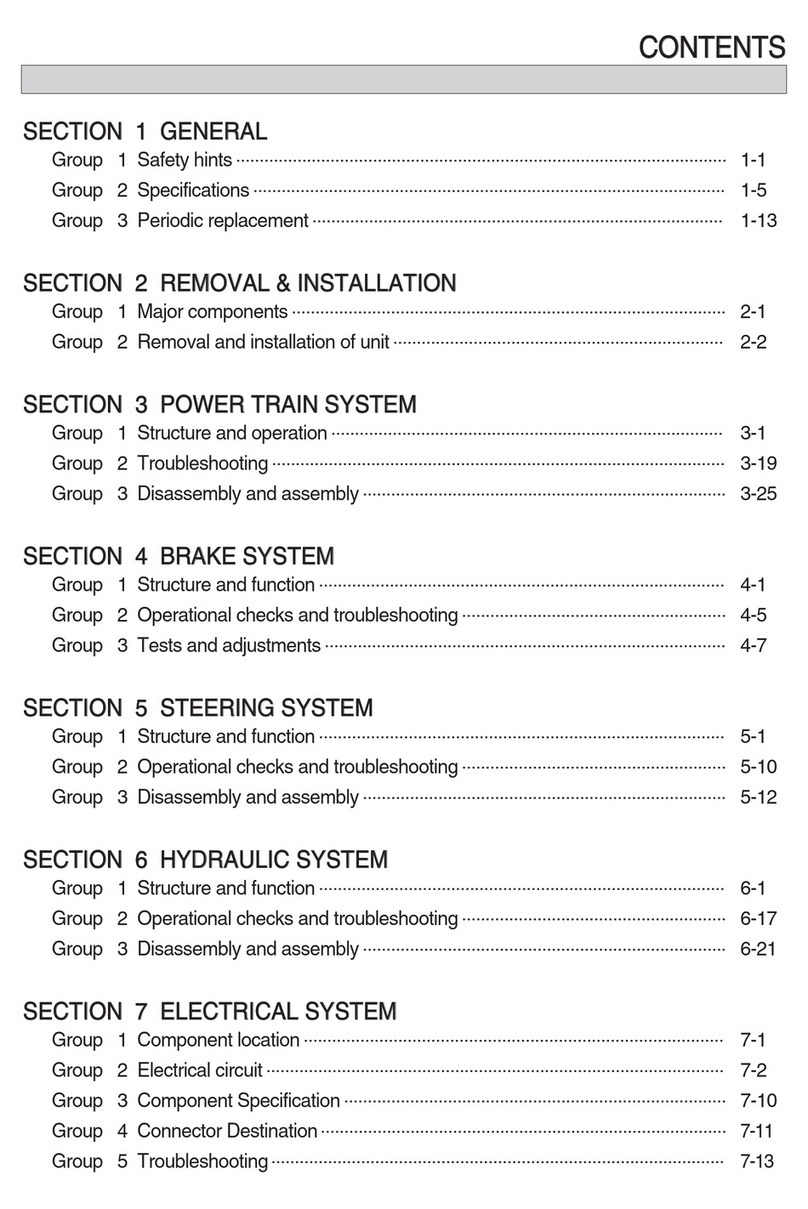
CONTENTS
SECTION 1 GENERAL
Group 1 Safety Hints
----------------------------------------------------------------------------------------------------
1-1
Group 2 Specifications
------------------------------------------------------------------------------------------------
1-5
Group 3 Periodic Replacement
-----------------------------------------------------------------------------------
1-13
SECTION 2 REMOVAL AND INSTALLATION OF UNIT
Group 1 Structure
--------------------------------------------------------------------------------------------------------
2-1
Group 2 Removal and Installation of Unit
--------------------------------------------------------------------
2-2
SECTION 3 POWER TRAIN SYSTEM
Group 1 Structure and Operation
--------------------------------------------------------------------------------
3-1
Group 2 Troubleshooting
---------------------------------------------------------------------------------------------
3-19
Group 3 Disassembly and Assembly
--------------------------------------------------------------------------
3-25
SECTION 4 BRAKE SYSTEM
Group 1 Structure and Function
----------------------------------------------------------------------------------
4-1
Group 2 Operational Checks and Troubleshooting
-----------------------------------------------------
4-8
Group 3 Tests and Adjustments
----------------------------------------------------------------------------------
4-10
SECTION 5 STEERING SYSTEM
Group 1 Structure and Function
----------------------------------------------------------------------------------
5-1
Group 2 Operational Checks and Troubleshooting
-----------------------------------------------------
5-10
Group 3 Disassembly and Assembly
--------------------------------------------------------------------------
5-12
SECTION 6 HYDRAULIC SYSTEM
Group 1 Structure and Function
----------------------------------------------------------------------------------
6-1
Group 2 Operational Checks and Troubleshooting
-----------------------------------------------------
6-22
Group 3 Disassembly and Assembly
--------------------------------------------------------------------------
6-26
SECTION 7 ELECTRICAL SYSTEM
Group 1 Component Location
-------------------------------------------------------------------------------------
7-1
Group 2 Electrical Circuit
---------------------------------------------------------------------------------------------
7-2
Group 3 Component Specification
------------------------------------------------------------------------------
7-9
Group 4 Connector Destination
-----------------------------------------------------------------------------------
7-10
Group 5 Troubleshooting
---------------------------------------------------------------------------------------------
7-12

SECTION 8 MAST
Group 1 Structure
--------------------------------------------------------------------------------------------------------
8-1
Group 2 Operational Checks and Troubleshooting
-----------------------------------------------------
8-4
Group 3 Adjustment
----------------------------------------------------------------------------------------------------
8-7
Group 4 Removal and Installation
-------------------------------------------------------------------------------
8-10

0-1
FOREWORD
1. STRUCTURE
This service manual has been prepared as an aid to improve the quality of repairs by giving the
serviceman an accurate understanding of the product and by showing him the correct way to perform
repairs and make judgements. Make sure you understand the contents of this manual and use it to
full effect at every opportunity.
This service manual mainly contains the necessary technical information for operations performed in
a service workshop.
For ease of understanding, the manual is divided into the following sections.
SECTION 1 GENERAL
This section gives the general information of the machine and explains the safety hints for
maintenance.
SECTION 2 REMOVAL & INSTALLATION OF UNIT
This section explains the procedures and techniques of removal and installation of each component.
SECTION 3 POWER TRAIN SYSTEM
This section explains the structure of the transmission as well as control valve and drive axle.
SECTION 4 BRAKE SYSTEM
This section explains the brake piping, each component and operation.
SECTION 5 STEERING SYSTEM
This section explains the structure of the steering unit, priority valve, trail axle as well as steering
circuit and operation.
SECTION 6 HYDRAULIC SYSTEM
This section explains the structure of the gear pump, main control valve as well as work equipment
circuit, each component and operation.
SECTION 7 ELECTRICAL SYSTEM
This section explains the electrical circuit and each component.
It serves not only to give an understanding electrical system, but also serves as reference material for
troubleshooting.
SECTION 8 MAST
This section explains the structure of mast, carriage, backrest and forks.
The specifications contained in this service manual are subject to change at any time and without any
advance notice. Contact your HYUNDAI distributor for the latest information.

0-2
Revised edition mark(
ΗΘΙ
Ä)
When a manual is revised, an edition mark is
recorded on the bottom outside corner of the
pages.
R
Revisions
Revised pages are shown at the list of revised
pages on the between the contents page and
section 1 page.
Symbols
So that the shop manual can be of ample
practical use, important places for safety and
quality are marked with the following symbols.
2. HOW TO READ THE SERVICE MANUAL
Distribution and updating
Any additions, amendments or other changes will
be sent to HYUNDAI distributors.
Get the most up-to-date information before you
start any work.
Filing method
See the page number on the bottom of the
page.
File the pages in correct order.
Following examples shows how to read the
page number.
Example 1
2 - 3
Item number(2. Structure and
Function)
Consecutive page number for
each item.
Additional pages : Additional pages are
indicated by a hyphen(-) and number after the
page number. File as in the example.
1.
2.
3.
Symbol Item Remarks
Special safety precautions are
necessary when performing the
work.
Extra special safety precautions
are necessary when performing
the work because it is under
internal pressure.
Special technical precautions or
other precautions for preserving
standards are necessary when
performing the work.
Safety
Caution
ö
10 - 4
10 - 4 - 1
10 - 4 - 2
10 - 5
Added pages

0-3
3. CONVERSION TABLE
Method of using the Conversion Table
The Conversion Table in this section is provided to enable simple conversion of figures. For details of
the method of using the Conversion Table, see the example given below.
Example
Method of using the Conversion Table to convert from millimeters to inches
Convert 55
mm
into inches.
Locate the number 50
in
the vertical column at the left side, take this as ͽ, then draw a
horizontal line from ͽ.
Locate the number 5
in
the row across the top, take this as ;, then draw a perpendicular line
down from ;.
Take the point where the two lines cross as Ϳ. This point Ϳgives the value when converting
from millimeters to inches. Therefore, 55
mm
= 2.165 inches.
Convert 550
mm
into inches.
The number 550 does not appear in the table, so divide by 10(Move the decimal point one place
to the left) to convert it to 55
mm
.
Carry out the same procedure as above to convert 55mm to 2.165 inches.
The original value(550
mm
) was divided by 10, so multiply 2.165 inches by 10(Move the decimal
point one place to the right) to return to the original value.
This gives 550
mm
= 21.65 inches.
1.
2.
(1)
(2)
(3)
(1)
(2)
(3)
Millimeters to inches 1
mm
= 0.03937 in
;
ͽ
01 2 345 678 9
0 0.039 0.079 0.118 0.157 0.197 0.236 0.276 0.315 0.354
10 0.394 0.433 0.472 0.512 0.551 0.591 0.630 0.669 0.709 0.748
20 0.787 0.827 0.866 0.906 0.945 0.984 1.024 1.063 1.102 1.142
30 1.181 1.220 1.260 1.299 1.339 1.378 1.417 1.457 1.496 1.536
40 1.575 1.614 1.654 1.693 1.732 1.772 1.811 1.850 1.890 1.929
50 1.969 2.008 2.047 2.087 2.126 2.165 2.205 2.244 2.283 2.323
60 2.362 2.402 2.441 2.480 2.520 2.559 2.598 2.638 2.677 2.717
70 2.756 2.795 2.835 2.874 2.913 2.953 2.992 3.032 3.071 3.110
80 3.150 3.189 3.228 3.268 3.307 3.346 3.386 3.425 3.465 3.504
90 3.543 3.583 3.622 3.661 3.701 3.740 3.780 3.819 3.858 3.898
Ϳ

0-4
Millimeters to inches 1
mm
= 0.03937
in
01 2 345 678 9
0 0.039 0.079 0.118 0.157 0.197 0.236 0.276 0.315 0.354
10 0.394 0.433 0.472 0.512 0.551 0.591 0.630 0.669 0.709 0.748
20 0.787 0.827 0.866 0.906 0.945 0.984 1.024 1.063 1.102 1.142
30 1.181 1.220 1.260 1.299 1.339 1.378 1.417 1.457 1.496 1.536
40 1.575 1.614 1.654 1.693 1.732 1.772 1.811 1.850 1.890 1.929
50 1.969 2.008 2.047 2.087 2.126 2.165 2.205 2.244 2.283 2.323
60 2.362 2.402 2.441 2.480 2.520 2.559 2.598 2.638 2.677 2.717
70 2.756 2.795 2.835 2.874 2.913 2.953 2.992 3.032 3.071 3.110
80 3.150 3.189 3.228 3.268 3.307 3.346 3.386 3.425 3.465 3.504
90 3.543 3.583 3.622 3.661 3.701 3.740 3.780 3.819 3.858 3.898
Kilogram to Pound 1
kg
= 2.2046
lb
01 2 345 678 9
0 2.20 4.41 6.61 8.82 11.02 13.23 15.43 17.64 19.84
10 22.05 24.25 26.46 28.66 30.86 33.07 35.27 37.48 39.68 41.89
20 44.09 46.30 48.50 50.71 51.91 55.12 57.32 59.5. 61.73 63.93
30 66.14 68.34 70.55 72.75 74.96 77.16 79.37 81.57 83.78 85.98
40 88.18 90.39 92.59 94.80 97.00 99.21 101.41 103.62 105.82 108.03
50 110.23 112.44 114.64 116.85 119.05 121.25 123.46 125.66 127.87 130.07
60 132.28 134.48 136.69 138.89 141.10 143.30 145.51 147.71 149.91 152.12
70 154.32 156.53 158.73 160.94 163.14 165.35 167.55 169.76 171.96 174.17
80 176.37 178.57 180.78 182.98 185.19 187.39 189.60 191.80 194.01 196.21
90 198.42 200.62 202.83 205.03 207.24 209.44 211.64 213.85 216.05 218.26

0-5
Liter to U.S. Gallon 1˶= 0.2642 U.S.Gal
01 2 345 678 9
0 0.264 0.528 0.793 1.057 1.321 1.585 1.849 2.113 2.378
10 2.642 2.906 3.170 3.434 3.698 3.963 4.227 4.491 4.755 5.019
20 5.283 5.548 5.812 6.6076 6.340 6.604 6.869 7.133 7.397 7.661
30 7.925 8.189 8.454 8.718 8.982 9.246 9.510 9.774 10.039 10.303
40 10.567 10.831 11.095 11.359 11.624 11.888 12.152 12.416 12.680 12.944
50 13.209 13.473 13.737 14.001 14.265 14.529 14.795 15.058 15.322 15.586
60 15.850 16.115 16.379 16.643 16.907 17.171 17.435 17.700 17.964 18.228
70 18.492 18.756 19.020 19.285 19.549 19.813 20.077 20.341 20.605 20.870
80 21.134 21.398 21.662 21.926 22.190 22.455 22.719 22.983 23.247 23.511
90 23.775 24.040 24.304 24.568 24.832 25.096 25.631 25.625 25.889 26.153
Liter to U.K. Gallon 1˶= 0.21997 U.K.Gal
01 2 345 678 9
0 0.220 0.440 0.660 0.880 1.100 1.320 1.540 1.760 1.980
10 2.200 2.420 2.640 2.860 3.080 3.300 3.520 3.740 3.950 4.179
20 4.399 4.619 4.839 5.059 5.279 5.499 5.719 5.939 6.159 6.379
30 6.599 6.819 7.039 7.259 7.479 7.969 7.919 8.139 8.359 8.579
40 8.799 9.019 9.239 9.459 9.679 9.899 10.119 10.339 10.559 10.778
50 10.998 11.281 11.438 11.658 11.878 12.098 12.318 12.528 12.758 12.978
60 13.198 13.418 13.638 13.858 14.078 14.298 14.518 14.738 14.958 15.178
70 15.398 15.618 15.838 16.058 16.278 16.498 16.718 16.938 17.158 17.378
80 17.598 17.818 18.037 18.257 18.477 18.697 18.917 19.137 19.357 19.577
90 19.797 20.017 20.237 20.457 20.677 20.897 21.117 21.337 21.557 21.777

0-6
kgfÂm
to
lbfÂft
1
kgfÂm
= 7.233
lbfÂft
01 2 345 678 9
7.2 14.5 21.7 28.9 36.2 43.4 50.6 57.9 65.1
10 72.3 79.6 86.8 94.0 101.3 108.5 115.7 123.0 130.2 137.4
20 144.7 151.9 159.1 166.4 173.6 180.8 188.1 195.3 202.5 209.8
30 217.0 224.2 231.5 238.7 245.9 253.2 260.4 267.6 274.9 282.1
40 289.3 396.6 303.8 311.0 318.3 325.5 332.7 340.0 347.2 354.4
50 361.7 368.9 376.1 383.4 390.6 397.8 405.1 412.3 419.5 426.8
60 434.0 441.2 448.5 455.7 462.9 470.2 477.4 484.6 491.8 499.1
70 506.3 513.5 520.8 528.0 535.2 542.5 549.7 556.9 564.2 571.4
80 578.6 585.9 593.1 600.3 607.6 614.8 622.0 629.3 636.5 643.7
90 651.0 658.2 665.4 672.7 679.9 687.1 694.4 701.6 708.8 716.1
100 723.3 730.5 737.8 745.0 752.2 759.5 766.7 773.9 781.2 788.4
110 795.6 802.9 810.1 817.3 824.6 831.8 839.0 846.3 853.5 860.7
120 868.0 875.2 882.4 889.7 896.9 904.1 911.4 918.6 925.8 933.1
130 940.3 947.5 954.8 962.0 969.2 976.5 983.7 990.9 998.2 10005.4
140 1012.6 1019.9 1027.1 1034.3 1041.5 1048.8 1056.0 1063.2 1070.5 1077.7
150 1084.9 1092.2 1099.4 1106.6 1113.9 1121.1 1128.3 1135.6 1142.8 1150.0
160 1157.3 1164.5 1171.7 1179.0 1186.2 1193.4 1200.7 1207.9 1215.1 1222.4
170 1129.6 1236.8 1244.1 1251.3 1258.5 1265.8 1273.0 1280.1 1287.5 1294.7
180 1301.9 1309.2 1316.4 1323.6 1330.9 1338.1 1345.3 1352.6 1359.8 1367.0
190 1374.3 1381.5 1388.7 1396.0 1403.2 1410.4 1417.7 1424.9 1432.1 1439.4

0-7
kgf/cm2
to
lbf/in2
1
kgf / cm2
= 14.2233
lbf / in
2
01 2 345 678 9
14.2 28.4 42.7 56.9 71.1 85.3 99.6 113.8 128.0
10 142.2 156.5 170.7 184.9 199.1 213.4 227.6 241.8 256.0 270.2
20 284.5 298.7 312.9 327.1 341.4 355.6 369.8 384.0 398.3 412.5
30 426.7 440.9 455.1 469.4 483.6 497.8 512.0 526.3 540.5 554.7
40 568.9 583.2 597.4 611.6 625.8 640.1 654.3 668.5 682.7 696.9
50 711.2 725.4 739.6 753.8 768.1 782.3 796.5 810.7 825.0 839.2
60 853.4 867.6 881.8 896.1 910.3 924.5 938.7 953.0 967.2 981.4
70 995.6 1010 1024 1038 1053 1067 1081 1095 1109 1124
80 1138 1152 1166 1181 1195 1209 1223 1237 1252 1266
90 1280 1294 1309 1323 1337 1351 1365 1380 1394 1408
100 1422 1437 1451 1465 1479 1493 1508 1522 1536 1550
110 1565 1579 1593 1607 1621 1636 1650 1664 1678 1693
120 1707 1721 1735 1749 1764 1778 1792 1806 1821 1835
130 1849 2863 1877 1892 1906 1920 1934 1949 1963 1977
140 1991 2005 2020 2034 2048 2062 2077 2091 2105 2119
150 2134 2148 2162 2176 2190 2205 2219 2233 2247 2262
160 2276 2290 2304 2318 2333 2347 2361 2375 2389 2404
170 2418 2432 2446 2460 2475 2489 2503 2518 2532 2546
180 2560 2574 2589 5603 2617 2631 2646 2660 2674 2688
200 2845 2859 2873 2887 2901 2916 2930 2944 2958 2973
210 2987 3001 3015 3030 3044 3058 3072 3086 3101 3115
220 3129 3143 3158 3172 3186 3200 3214 3229 3243 3257
230 3271 3286 3300 3314 3328 3343 3357 3371 3385 3399
240 3414 3428 3442 3456 3470 3485 3499 3513 3527 3542

TEMPERATURE
Fahrenheit-Centigrade Conversion.
A simple way to convert a fahrenheit temperature reading into a centigrade temperature reading or vice
verse is to enter the accompanying table in the center or boldface column of figures.
These figures refer to the temperature in either Fahrenheit or Centigrade degrees.
If it is desired to convert from Fahrenheit to Centigrade degrees, consider the center column as a table of
Fahrenheit temperatures and read the corresponding Centigrade temperature in the column at the left.
If it is desired to convert from Centigrade to Fahrenheit degrees, consider the center column as a table
of Centigrade values, and read the corresponding Fahrenheit temperature on the right.
0-8
ÁCÁFÁCÁFÁCÁFÁCÁF
-40.4 -40 -40.0 -11.7 11 51.8 7.8 46 114.8 27.2 81 117.8
-37.2 -35 -31.0 -11.1 12 53.6 8.3 47 116.6 27.8 82 179.6
-34.4 -30 -22.0 -10.6 13 55.4 8.9 48 118.4 28.3 83 181.4
-31.7 -25 -13.0 -10.0 14 57.2 9.4 49 120.2 28.9 84 183.2
-28.9 -20 -4.0 -9.4 15 59.0 10.0 50 122.0 29.4 85 185.0
-28.3 -19 -2.2 -8.9 16 60.8 10.6 51 123.8 30.0 86 186.8
-27.8 -18 -0.4 -8.3 17 62.6 11.1 52 125.6 30.6 87 188.6
-27.2 -17 1.4 -7.8 18 64.4 11.7 53 127.4 31.1 88 190.4
-26.7 -16 3.2 -6.7 20 68.0 12.8 55 131.0 32.2 90 194.0
-26.1 -15 5.0 -6.7 20 68.0 12.8 55 131.0 32.2 90 194.0
-25.6 -14 6.8 -6.1 21 69.8 13.3 56 132.8 32.8 91 195.8
-25.0 -13 8.6 -5.6 22 71.6 13.9 57 134.6 33.3 92 197.6
-24.4 -12 10.4 -5.0 23 73.4 14.4 58 136.4 33.9 93 199.4
-23.9 -11 12.2 -4.4 24 75.2 15.0 59 138.2 34.4 94 201.2
-23.3 -10 14.0 -3.9 25 77.0 15.6 60 140.0 35.0 95 203.0
-22.8 -9 15.8 -3.3 26 78.8 16.1 61 141.8 35.6 96 204.8
-22.2 -8 17.6 -2.8 27 80.6 16.7 62 143.6 36.1 97 206.6
-21.7 -7 19.4 -2.2 28 82.4 17.2 63 145.4 36.7 98 208.4
-21.1 -6 21.2 -1.7 29 84.2 17.8 64 147.2 37.2 99 210.2
-20.6 -5 23.0 -1.1 35 95.0 21.1 70 158.0 51.7 125 257.0
-20.0 -4 24.8 -0.6 31 87.8 18.9 66 150.8 40.6 105 221.0
-19.4 -3 26.6 0 32 89.6 19.4 67 152.6 43.3 110 230.0
-18.9 -2 28.4 0.6 33 91.4 20.0 68 154.4 46.1 115 239.0
-18.3 -1 30.2 1.1 34 93.2 20.6 69 156.2 48.9 120 248.0
-17.8 0 32.0 1.7 35 95.0 21.1 70 158.0 51.7 125 257.0
-17.2 1 33.8 2.2 36 96.8 21.7 71 159.8 54.4 130 266.0
-16.7 2 35.6 2.8 37 98.6 22.2 72 161.6 57.2 135 275.0
-16.1 3 37.4 3.3 38 100.4 22.8 73 163.4 60.0 140 284.0
-15.6 4 39.2 3.9 39 102.2 23.3 74 165.2 62.7 145 293.0
-15.0 5 41.0 4.4 40 104.0 23.9 75 167.0 65.6 150 302.0
-14.4 6 42.8 5.0 41 105.8 24.4 76 168.8 68.3 155 311.0
-13.9 7 44.6 5.6 42 107.6 25.0 77 170.6 71.1 160 320.0
-13.3 8 46.4 6.1 43 109.4 25.6 78 172.4 73.9 165 329.0
-12.8 9 48.2 6.7 44 111.2 26.1 79 174.2 76.7 170 338.0
-12.2 10 50.0 7.2 45 113.0 26.7 80 176.0 79.4 172 347.0

SECTION 1 GENERAL
Group 1 Safety Hints
----------------------------------------------------------------------------------------------------
1-1
Group 2 Specifications
-------------------------------------------------------------------------------------------------
1-5
Group 3 Periodic Replacement
------------------------------------------------------------------------------------
1-13

1-1
Careless performing of the easy work may cause injuries.
Take care to always perform work safely, at least observing the following.
Oil is a dangerous substance. Never handle
oil, grease or oily clothes in places where
there is any fire of flame.
As preparation in case of fire, always know
the location and directions for use of fire
extinguishers and other fire fighting equipment.
ÂÂ
Wear well-fitting helmet, safety shoes and
working clothes. When drilling, grinding or
hammering, always wear protective goggles.
Always do up safety clothes properly so that
they do not catch on protruding parts of
machines. Do not wear oily clothes.
When checking, always release battery plug.
ÂÂ
Flames should never be used instead of
lamps. Never use a naked flame to check
leaks or the level of oil or electrolyte.
ÂÂ
Exhaust gas is dangerous. Provide adequate
ventilation when working a closed space.
Â
Â
D35ASF01
D35ASF02
D35ASF03
D35ASF04
GROUP 1 SAFETY HINTS

1-2
Be particularly careful when removing the
radiator cap and the hydraulic oil tank filler
cap, if this is done immediately after using
the machine, there is a danger that boiled
oil may spurt out.
The procedure for releasing the hydraulic
pressure is as follows : lower the fork to the ground,
and stop the engine(Motor), move the control
levers to each position two or three times.
Â
When working on top of the machine, be
careful not to lose your balance and fall.
Â
Hand a caution sign in the operator's compartment
(For example Do not start or Maintenance in
progress).
This will prevent anyone from starting or
moving the machine by mistake.
It is extremely dangerous to try to check
the fan belt tension while the engine is
running.
Â
When inspecting the engine is running parts,
or
near such parts, always stop the engine first.
Before checking or servicing accumulator or
piping, depress brake pedal repeatedly to
release pressure.
Park the machine on firm, flat ground.
Lower the fork to the ground and stop the
engine.
Return each lever to NEUTRAL and apply
the brake lock.
Â
D35ASF05
D35ASF06
D35ASF07
D35ASF08

1-3
Immediately remove any oil or grease on the
floor of the operator's compartment, or on the
handrail. It is very dangerous if someone
slips while on the machine.
Â
OIL
When working with others, choose a group
leader and work according to his instructions.
Do not perform any maintenance beyond the
agreed work.
Â
Unless you have special instructions to the
contrary, maintenance should always be
carried out with the engine stopped. If
maintenance is carried out with the engine
running, there must be two men present : one
sitting in the operator's seat and the other one
performing the maintenance. In such a case,
never touch any moving part.
Â
Always remember that the hydraulic oil circuit
is under pressure. When feeding or draining
the oil or carrying out inspection and
maintenance, release the pressure first.
Â
D35ASF09
D35ASF10
D35ASF11

1-4
Thoroughly clean the machine. In particular, be careful to clean the filler caps, grease fittings and the
area around the dipsticks. Be careful not to let any dirt or dust into the system.
Always use HYUNDAI Forklift genuine parts for replacement.
Always use the grades of grease and oil recommended by HYUNDAI Forklift.
Choose the viscosity specified for the ambient temperature.
Always use pure oil or grease, and be sure to use clean containers.
When checking or changing the oil, do it in a place free of dust, and prevent any dirt from getting into
the oil.
Before draining the oil, warm it up to a temperature of 30 to 40ÁC.
After replacing oil, filter element or strainer, bleed the air from circuit.
When the strainer is located in the oil filler, the strainer must not be removed while adding oil.
When changing the oil filter, check the drained oil and filter for any signs of excessive metal particles
or other foreign materials.
When removing parts containing O-ring, gaskets or seals, clean the mounting surface and replace
with new sealing parts.
After injecting grease, always wipe off the oil grease that was forced out.
Do not handle electrical equipment while wearing wet places, as this can cause electric shock.
During maintenance, do not allow any unauthorized person to stand near the machine.
Be sure you fully understand the contents of the operation. It is important to prepare necessary tools
and parts and to keep the operating area clean.
When checking an open gear case, there is a risk of dropping things in. Before removing the covers
to inspect such cases, empty everything from your pockets. Be particularly careful to remove
wrenches and nuts.
Way to use dipstick
Push the dipstick fully into the guide, and then pull out.
Carrying out other difficult maintenance work carelessly can cause unexpected accidents. If you
consider the maintenance is too difficult, always request the HYUNDAI Forklift distributor to carry out it.
Â
Â
Â
Â
Â
Â
Â
Â
Â
Â
Â
Â
Â
Â
Â
Â

1-5
GROUP 2 SPECIFICATIONS
1. GENERAL LOCATIONS
9
10
17
16
15
14
13
21
18
19
20
1
2
3
4
7
6
5
811
12
15L7MOM57
1 Steering wheel
2 Mast
3 Lift chain
4 Lift cylinder
5 Cluster
6 Backrest
7 Carriage
8Forks
9 Tilt cylinder
10 Front wheel
11 Bonnet
12 Rear wheel
13 Counterweight
14 Seat
15 LPG tank
16 Clamp
17 Overhead guard
18 Rear combination lamp
19 Turn signal lamp
20 Head lamp
21 Sub bonnet

1-6
2. SPECIFICATIONS
A
B
R
L,W,T
C/C'
D
E
F
kg(lb)
mm(in)
kg(lb)
mm(ft·in)
mm(ft·in)
mm/sec
mm/sec
mm(inch)
degree
mm(ft·in)
mm(ft·in)
km/h
%
mm
Overall length
Overall width
Overhead guard height
Ground clearance(Load)
Wheel base
Wheel tread front/rear
mm(ft·in)
mm(ft·in)
mm(ft·in)
mm(ft·in)
mm(ft·in)
mm(ft·in)
2233(7' 4")
1070(3' 6")
2110(6' 11")
120(0' 5")
1410(4' 8")
890/910(2' 11"/3' 0")
2263(7' 5")
←
←
←
←
←
2308(7' 7")
←
←
←
←
←
Capacity
Load center
Weight(Unloaded)
Model Unit 15L(G)-7M 18L(G)-7M 20L(G)-7M
Lifting height
Free lift
Lifting speed(Unload/Load)
Lowering speed(Unload/Load)
L
×
W
×
T
Tilt angle (Forward/Backward)
Max height
Min height
Travel speed(Unload)
Gradeability(Load)
Min turning radius(Outside)
1500(3000)
500(24")
2788(6146)
3325(10' 11")
145(0' 6")
680/650
450/500
900
×
100
×
35
(35.4
×
3.9
×
1.4)
6/10
4332(14' 3")
2155(7' 1")
20.1
39.7
1730(5' 8")
1800(3500)
←
2962(6530)
←
←
←
←
←
←
←
←
←
35.4
1746(5' 9")
2000(4000)
←
3109(6854)
3330(10' 11")
150(0' 6")
←
←
900
×
100
×
40
(35.4
×
3.9
×
1.4)
←
←
←
←
33.0
1760(5' 9")
Fork
Mast
Body
K
I
C
L
B
EE
A
D
C'
R
G
J
T
F
H
M
W
M'
G
H
I
J
K
M, M'
ETC Hydraulic oil tank
Fuel tank(Gasoline)
33(8.7)
44(11.6)
←
←
←
←
ℓ
(usgal)
ℓ
(usgal)
25L7SP01

1-7
3. SPECIFICATION FOR MAJOR COMPONENTS
MAIN PUMP
2)
Item
Type
Capacity
Maximum operating pressure
Rated speed (Max/Min)
cc/rev
bar
rpm
Gear
26
250
2700/500
Unit Specification
MMAIN CONTROL VALVE
3)
Item
Type
Operating method
Relief valve pressure(Main/Aux)
Flow capacity
bar
lpm
Sectional
Mechanical
190/150
80
Unit Specification
Item
Model
Type
Cooling Method
Number of cylinders and arrangement
Firing order
Cylinder bore X stroke
Piston displacement
Compression ratio
Rated gross horse power
Maximum gross torque at rpm
Engine oil quantity
Dry weight
High idling speed
Low idling speed
Rated fuel consumption
Starting motor
Alternator
Battery
Fan belt deflection
Unit
mm(in)
cc(cu in)
ps/rpm
kgfÂm/rpm
˶
(U.S.gal)
kg(lb)
rpm
rpm
g/ps.hr
V-kW
V-A
V-AH
mm(in)
Specification
HYUNDAI, L4KB [Theta]
4-cycle, vertical
Water cooled
4 cylinders, In line
1-3-4-2
88Ý97(3.46
Ý
3.82)
2359(143.95)
10.5
50/2450
16.3/1600
5.7(1.5)
160(352)
2700
800
-
12 - 1.2
12 - 75
12 - 60
10~15(0.4~0.6)
EENGINE
1)

1-8
POWER TRAIN DEVICES
5)
Item Specification
Torque converter
Transmission
Axle
Wheels
Brakes
Steering
Model
Type
Stall ratio
Type
Gear shift(FR/RR)
Adjustment
Type
Gear ratio
Gear
Q'ty(FR/RR)
Gear ratio
Front
Rear
FR
RR
KAPEC 280DB
3 Element, 1 stage, 2 phase
2.9 : 1
Power shift
1/1
Electrical single lever type, kick down system
1 : 1
1 : 1
Front-wheel drive type, fixed location
14.2 : 1
Ring & pinion gear type
2/2
6.50-10-12PR
5.00-8-10PR
Front wheel, wet disk brake
Ratchet, wet disk brake
Hydro static, power steering
81äto both right and left angle, respectively
Travel
Parking
Type
Steering angle
SSTEERING UNIT
4)
Item
Type
Capacity
Max. input pressure
Back pressure
Input torque
cc/rev
Mpa
Mpa
N.m
120
22.7
2
1.5Ü0.2
Unit Specification
Load sensing/Non load reaction/Dynamic signal

1-9
4. TIGHTENING TORQUE OF MAJOR COMPONENTS
NO
1
2
3
4
5
6
7
8
9
10
11
12
13
ITEMS SIZE
Engine
Others
Engine mounting bolt, nut
Radiator mounting bolt, nut
Torque converter mounting bolt
MCV mounting bolt, nut
Steering unit mounting bolt
Transmission mounting bolt, nut
Drive axle mounting bolt, nut
Steering axle mounting bolt, nut
Front wheel mounting nut
Rear wheel mounting nut
Counterweight mounting bolt
Operator's seat mounting nut
Head guard mounting bolt
M12Ý1.25
M 8Ý1.25
M10Ý1.25
M10Ý1.5
M10Ý1.5
M16Ý2.0
M20Ý1.5
M20Ý2.5
M14Ý1.5
M12Ý1.5
M30Ý3.5
M 8Ý1.25
M12Ý1.75
12.5Ü2.5
2.5Ü0.5
6.9Ü1.4
4.0Ü0.5
4.0Ü0.5
7.5
65Ü3
58Ü8.5
17.5Ü1.5
10Ü1
60Ü5
2.5Ü0.5
6.2
90Ü18
18.1Ü3.6
50Ü10
29Ü3.6
29Ü3.6
54
470Ü21.6
420Ü61
127Ü10.8
72Ü7.2
434Ü36
18.1Ü3.6
44.8
kgf
Â
m lbf
Â
ft
Hydraulic
system
Power
train
system
This manual suits for next models
3
Other Hyundai Forklift manuals

Hyundai
Hyundai 100D-7 User manual

Hyundai
Hyundai 15EPM User manual

Hyundai
Hyundai HBF 15III User manual

Hyundai
Hyundai 15LC-7M User manual

Hyundai
Hyundai 25DE-7U User manual

Hyundai
Hyundai 15ES User manual

Hyundai
Hyundai 20DT-7 User manual

Hyundai
Hyundai 160D-9L User manual

Hyundai
Hyundai 14BRJ-7 User manual

Hyundai
Hyundai 25DE-7 User manual

Hyundai
Hyundai 250D-7E User manual

Hyundai
Hyundai 10BOP-7 User manual

Hyundai
Hyundai 50DS-7E User manual

Hyundai
Hyundai 20D-7E User manual

Hyundai
Hyundai HBR 14-7 User manual

Hyundai
Hyundai 14BRJ-7 User manual

Hyundai
Hyundai HDF 35III User manual

Hyundai
Hyundai 12ESH User manual

Hyundai
Hyundai 15D-7E User manual

Hyundai
Hyundai 35D-7E User manual