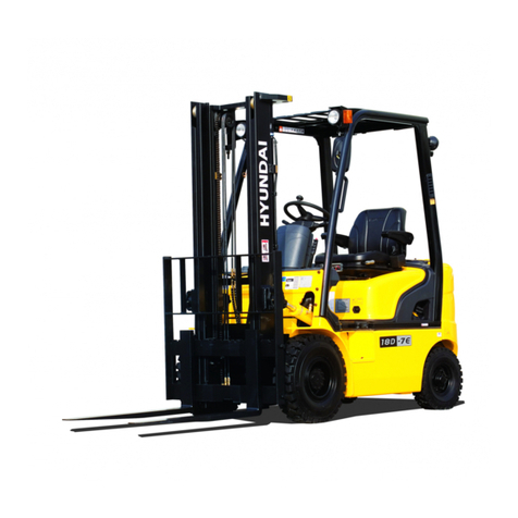
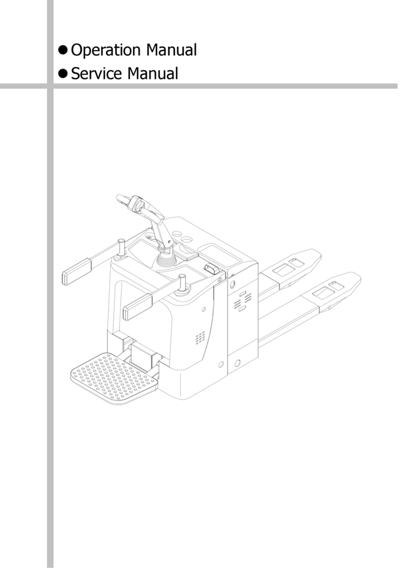
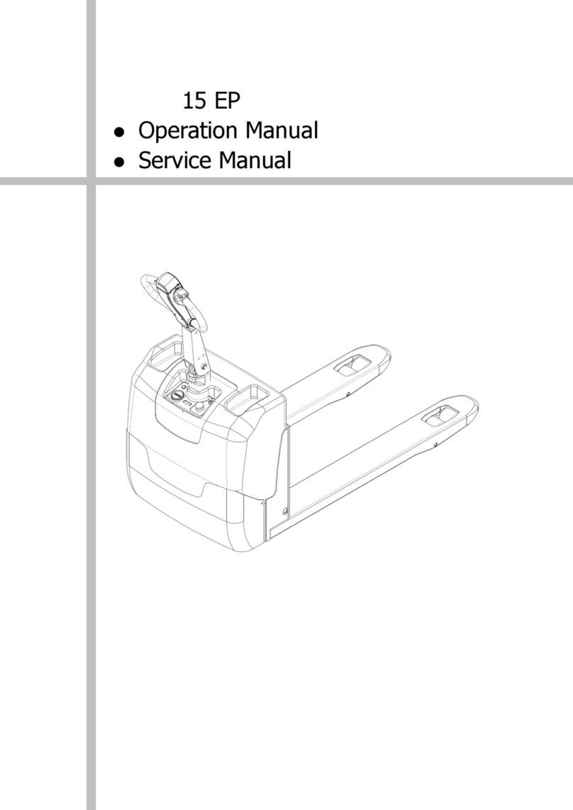
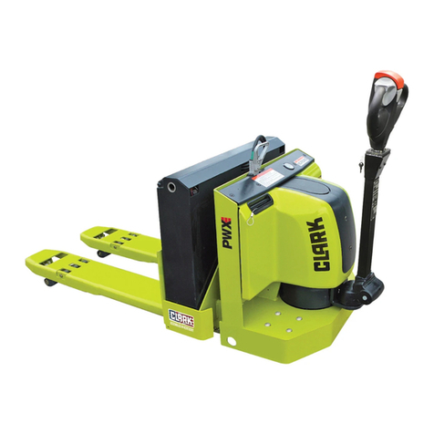
Hyundai 20EP User manual

20EP
Operation manual
Service Manual

We hope our electric pallet truck 20EP will provide great convenience for
your work!Please read the manual carefully before operation。
This manual is universal manual. We reserve the right to modify
technology of the electric stacker. If there is anything in the manual that
is not consistent with the actual stacker, the actual stacker should be
considered correct and the manual is only for reference。
*****************************************************
Warning
Operator of the truck must strictly follow ISO 3691“Safety Specification for
Industrial Vehicles” and it is prohibited for untrained people to operate the
truck.
*****************************************************
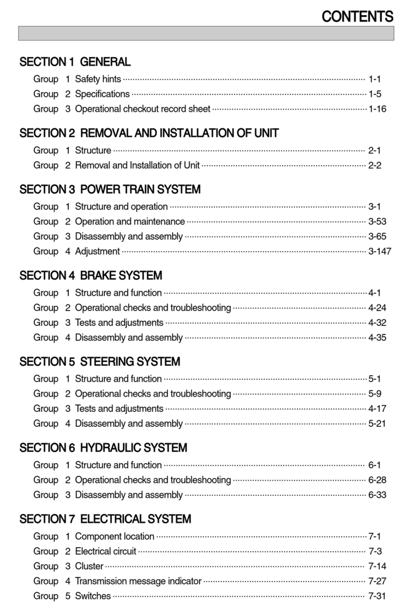
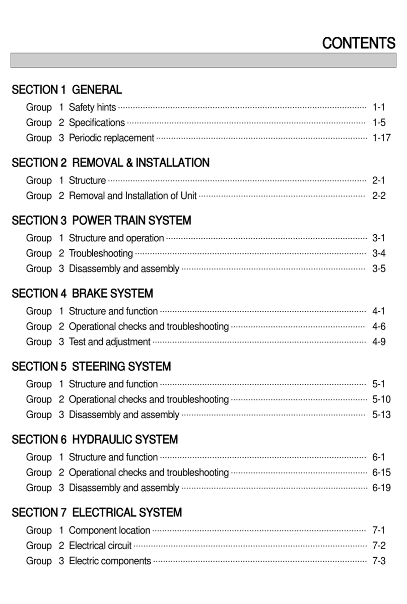
Table of Contents
1.Contour diagram……………………………………………..………….1
2.Brief technical parameters…………………………………………….2
3.Applications…………………………………………………………………3
4.Structure……………………………………………………………………..3
5.Use and operation instructions……………………………………….3
6.Maintenance…………………………………………………………………5
7.Common faults and trouble shooting……………………..……….6
8.Maintenance and charge of the storage battery………………..8
9.List of accessories, spare parts and vulnerable parts…………10
10. Packing and transportation…………………………………………….10
11. Warning……………………………………………………………………….10
12. Structure diagram of the major parts………………..…………….11
13. Packing list………..………………………………………………………….14

1
1.Contour diagram

2
2.Brief technical parameters(Electric Pallet Truck)
Characte
ristics
1.1
Manufacturer
HCE
1.2
Model
20EP
1.3
Driving model
Electric
1.4
Driving model(Manual, Walking, Stand driving,
seat driving ,Order picking)
Walking
1.5
Rated load
Q(kg)
2045
1.6
Load center distance
c
(mm)
600
1.8
Axle center to fork face
x
(mm)
815/865/935
1.9
Tread
Y
(mm)
1211/1261/1331
weight
2.1
Service weight(with battery)
kg
620
2.2
Axle load, front/rear, laden
kg
1170/1450
2.3
Axle load, front/rear, unladen
kg
470/150
Chassis
3.1
Wheels (rubber, high elasticity, pneumatic tire,
polyurethane wheel)
polyurethane
3.2
Wheel dimension, front
Φ250×70
3.3
Wheel dimension, rear
Φ82×126
3.4
Additional wheel(dimension)
Φ127× 57
3.5
Wheel number, front/rear (x = driving wheel)
1X+2/2
3.6
Tread, front
b
10(mm)
510
3.7
Tread, rear
b
11(mm)
340/370/470/505
Dimensio
n
4.4
Lift height
h
3(mm)
120
4.9
Min./Max. height of operation handle in the
driving position
h
14(mm)
780/1230
4.15
Height, lowered
h
13(mm)
82
4.19
Overall length
l
1(mm)
1655/1705/1775
4.20
Length to fork face
l
2(mm)
555
4.21
Overall width of truck body
b
1(mm)
775
4.22
Fork dimension
S/e/l(mm)
54× 180× 1100
(1150/1220)
4.25
Fork width
b
5(mm)
520/550/650/685
4.32
Wheelbase ground distance
m
2(mm)
28
4.33
Aisle width, with pallet 1000x1200 crosswise
Ast
(mm)
2015/2065/2135
4.34
Aisle width, with pallet 800x1200 lengthwise
Ast
(mm)
2115/2115/2135
4.35
Turning radius
W
a(mm)
1400/1450/1520
Performa
nce
Data
5.1
Traveling speed, laden/unladen
Km/h
5.5/5.6
5.2
Lifting speed, laden/unladen
m/s
0.039/0.056
5.3
Descending speed, laden/ unladen
m/s
0.064/0.050
5.7
Grade ability, laden/unladen
%
6/12
5.8
Max. grade ability, laden/unladen
%
8/20
5.10
Traveling brake
Electromagnetic brake
Motor
6.1
Driving motor power
kW
1.2
6.2
Lifting motor power
kW
1.2
6.4
Battery voltage/rated capacity
V/Ah
24/165(210)
6.5
Battery weight
Kg
170
Battery dimension(LXWXH)
mm
750× 170× 474(534)
8.4
Noise level at operator’s ear, according to
DIN12053
dB(A)
70

3
3.Applications
20EP electric pallet truck,adopts storage batteries as the dynamic source and a AC motor as the driver,
traveling through gear transmission。The lifting of the fork relies on the DC motor and the hydraulic
transmission system. The up-and-down movement of the oil cylinders lifts the fork and the goods. As the
traveling and lifting of the stacker are electrically driven, it possesses the characteristics of energy saving,
high efficiency, stable operation, easy operation, safe and reliable, low noise and no pollution, etc.
Environment for application:
a. Elevation no more than 1200m;
b. Ambient temperature no higher than +40℃ and no lower than -25℃;
c. When the ambient temperature reaches +40℃, the relative humidity should not exceed 50%; at a
lower temperature, higher relative humidity is allowed;
d. Hard and level ground。
e. It is prohibited to use the truck in a flammable, explosive or corrosive environment with acid and
alkali。
4.Structure (See also the structure diagram and the principle
diagram of the major parts)
The truck mainly consists of electric drive wheel, steering assembly, front frame, back frame, lifting oil
cylinder, hydraulic station, electric control system, connecting rod wheel supporter and balance wheel,
etc。
5.Use and operation instructions
The truck adopts storage batteries as the power supply for goods handling and stacking and a AC motor
as the power source .to drive the truck and lift goods. Correct use and operation will bring you great
convenience in your work but incorrect use and operation will damage the truck and bring you and your
goods danger。
5.1 Before operation:
5.1.1 Before operation, please check if the truck is in normal condition: Is there any oil leakage in the
hydraulic pipes? Are the supporting wheels able to operate normally? Is there any block? The trucks
with problems are prohibited for operation.。
5.1.2 Check if there is any electric power in the batteries with the method indicated in Fig.I. Pull the
general power switch out to turn on the general power supply, unlock the electric lock on the handle,
check the electric energy meter on the instrument panel of the truck. If the zero end grid is bright,
it indicates there is no electric power in the batteries and charging should be conducted at once. It
Turn off the power
supply
Turn on the power
supply
Electric lock door
There is no electric
power in the batteries if
this grid is bright
Fig I

4
is prohibited to operate the truck
without electric power as that will
greatly reduce the service life of the
batteries and even damage the
batteries.。
5.1.4 Check if the truck brake is normal.
Check the lifting, dropping, forward
and backward traveling of the truck
to see if the actions are normal.
Check if the emergency reverse
action of the truck is normal with
the method indicated in Fig.II:
Move the control handle to division
A or division C as indicated in Fig.II
and press the rise/lowering button
on the control handle to see if the lifting and lowering of the fork is normal.
Move the control handle to division B as indicated in Fig. II slowly start the truck and press the
handle to the horizontal position to see if the truck can travel or brake normally.
Move the handle to division B as indicated in Fig. II and press the emergency reverse switch button
on top of the control handle to see if the truck can travel forward.
After the above check, if there is no failure in the truck, it can be put into operation; if there is some
failure, please repair it at once. It is prohibited to use trucks with problems.。
5.2 In operation:
5.2.1Note: A side-magnetic brake is installed on the shaft end of the drive wheel motor and there is a cam
and a fine motion switch installed on the rotary shaft of the rotary arm. Only the rotary arm is at
30°± 20° (as indicated in Fig.II), the truck can get power and operate. Larger or less than the
angle, the stacker has no power and is braked. In that case, the truck can lift goods. When
lifting goods, the truck cannot travel. As indicated in Fig.II, when the control handle is in
division A or division C, the truck can only lift or lower but not travel; when the control handle is
in division B, the truck can travel, lift as well as lower. The operation position of the handle will
not be specially described in the following descriptions, i.e. the handle must be in division A or C
when the truck lifts or lowers and it must be in division B when the truck is traveling
5.2.2 Operation of handling
As indicated in Fig.I, pull out the general power supply switch, unlock the electric door lock. Control
the travel knob, the truck moves forward when the knob point forward, and backward when the
knob backward. After start, rotate the knob slowly whether it is with or without load to reach the
rated speed smoothly. Move the truck near the goods pile (the head of the fork is 30cm from the
goods piles). Press the lowering button, adjust the height of the fork to a proper position, insert the
fork slowly and as deep as possible into the pallet of the goods. Press the lifting button till the fork
is ≥30cm from the ground. Stop lifting, move the truck to the desired location and then press the
lowering button after the truck stops. After the fork is completely away from the pallet, drive the
truck away from the pallet. The handling operation is finished
5.2.3Adjustment of the brake clearance
①Hollow screw
a) Fitting screw
b) Spring
c) Armature
Fig Ⅱ

5
d) Motor shaft
e) Spline housing
f) Friction plate
⑧Electromagnetic coil
⑨Mounting cover plate
⑩Mounting screw
The brake structure is indicated as the Fig on the
right. After being used for a while, the performance
of the brake may decline with the wearing of the
brake block or the brake plate can’t be released. At
this time, it is necessary to adjust brake clearance.
As indicated in the figure on the right, in braking
status, use a feeler to check the gap between the
brake block and electromagnet, if the gap is more than 0.5mm, then it needs adjustment. Before
adjustment, clean the dirt and dust on the friction plate. When adjusting, loosen the fixed screw 2,
adjust the length of set screw 1, then fasten the retention screws, after adjustment, the clearance
between the brake block and electromagnet should be fixed from 0.2~0.3mm. It has to be noted
that even adjustment for three retention screws can make even clearance gap between the brake
block and electromagnet after adjustment. After the adjustment, turn on the brake with 24v DC
power. Then the brake will make clear sound。
Be alert to obstacles when the truck travels. Slow down at turns.
Switch off the power immediately when the truck is out of control to cut off the power supply.
There is quick advance switch on the top of the handle assembly. The truck will advance quickly in a
reverse direction when it is moving backward after pressing the switch in case of emergency。
6.Maintenance
Note: It is prohibited for untrained personnel to maintain the truck
6.1 Whether the truck can operate satisfyingly depends on the efficient maintenance. When maintenance
is ignored, the truck may pose a threat to human lives and cause property damage. Routine
inspection should be conducted, when the truck is in operation, to eliminate abnormal conditions.
Never use a truck with trouble to ensure safety and to prolong the service life of the truck.
6.2 Maintenance: The maintenance of the truck is divided into three levels, i.e. routine maintenance, level
I maintenance and level II maintenance.
Routine maintenance: Daily maintenance is to clean the surface of the truck body and the surface of
the storage battery and to examine the firmness of the power supply cable.
Level I maintenance: Level I maintenance should be performed once every week. Besides what
should be done in daily maintenance, the operation situation of all the parts should be carefully
inspected to see whether the operation is normal; whether there is any loose of the fasteners; is
there any oil leakage at the hydraulic connection; is there any abnormal wearing and tearing in the
mechanical parts; is there any abnormal temperature rise or sparks in the electric part, etc. If there is
any abnormal situation, adjustment or trouble-shooting should be performed promptly.
Level II maintenance should be carried out as planned. Overall inspection should be performed for
the truck according to the following requirements.
a. Maintenance for mechanical system: Once half a year. The major content is to add lubricant to the
transmission gears and bearings of the drive wheel and the rotary joints, and examine the firmness of
the fixing fittings, the flexibility of the wheels, as well as whether the forks can be lifted and lowered
normally. Clean the dirt and dust on the friction plate of electromagnetic arrester and adjust the

6
clearance to the proper distance. The operation noise of the truck should be no more than 70dB after
maintenance.
b. Maintenance for hydraulic system: Once half a year. Examine if the oil cylinder is normal, if there is
any leakage externally or internally, if the hydraulic connection and the hose are reliable with no
leakage. The hydraulic oil should be kept clean and generally it should be replaced every 12 months.
ISO oil product standard is adopted for the hydraulic oil. When the ambient temperature is –5~ 40℃,
HL-N46 or HL-N68 should be used; when the ambient temperature is –35~ –5℃, HV-N46 or HV-N68
should be used. The replaced waste oil should be treated according to the local rules and regulations.
c. Maintenance for electric equipment: Once every three months. First examine whether the specific
gravity of the electrolytic solution of the storage battery [specific gravity at 1.24 (at 25℃) in
tropical areas and 1.26 (at 25℃) in other areas] fits and the terminals are clean. Otherwise, the
specific gravity of the electrolytic solution should be adjusted as required and the terminals should
be cleaned and painted with Vaseline and tightened. Examine if the connections of the electrical
devices are reliable, the switches are normal and the insulation is ok (The insulation resistance
between the electrical devices and the truck body should be above 0.5MΩ). Clean the dirt, dust,
and carbon fouling of motor. Meanwhile check the wearing condition of the electric brush and
replace it if necessary.
7.Common faults and trouble shooting
No.
Faults
Cause
Shooting
1
The truck can’t be
started.
(The contacts do not
work.)
①The fuse of the control circuit is burn
out.
Replace
②The power switch contact is bad or
damaged.
Repair or replace
③The fuse of the major circuit is broken.
Replace
④The contact of the electric lock switch
is bad or broken.
Repair or replace
⑤The connection of the storage
batteries is loose or has fallen off.
Tighten
The truck cannot be
started
(The contacts work.)
①The side-magnetic brake of the drive
wheel does not suck and the truck is
in a braked condition.
Repair or replace
②The walking motor carbon brush is
worn or bad contact between the
steering device and the carbon-brush.
Repair or replace
③The magnet-exciting coil of the
stepper motor is broken or bad
contact at the wire end.
Repair or replace
④Bad contact.
Repair or replace
⑤There is a trouble at the MOSFET tube
type circuit board.
Repair or replace
2
The truck can only
move forward
(or backward)
①Bad or broken contact.
Repair or replace
②There is a trouble in the circuit board.
Repair or replace
3
The truck can not
stop while traveling
Broken contact. The moving contact
cannot be reset.
Cut off the power at once
and replace the contact

7
4
The brake does not
work
①The erection bolt of the fine motion
switch looses or is damaged.
Adjust or tighten the bolt
or replace the fine
motion switch.
②The connecting wire of the
side-magnet brake is loose or the
side-magnetic brake is damaged
Tighten the bolt or repair
the side-magnet brake.
③The moving plates of the
side-magnetic brake is loose or
damaged.
Replace the braking
plates.
5
The steering has got
stuck
①The bearing of the steering device is
damaged.
Replace the bearing
②The bearing of the steering device
lacks lubricant or there is too much
dust
Clean the bearing
6
Difficult steering of
the drive wheel,
noise and the motor
is overloaded.
①The gear or bearing has got stuck
because of foreign matters.
Clean or replace the
bearing
②There is clearance in the bearing
installed or the fixing ring has come
off.
Reinstall the ring. Adjust
the clearance.
③The front wheel bearing is damaged.
Replace the bearing
7
The forks cannot be
lifted.
①Overload
Reduce the load
②The pressure of the overflow valve is
too low.
Adjust the pressure
higher
③Internal abnormal leakage in the lifting
oil cylinder.
Replace the seals
④Insufficient hydraulic oil
Add appropriate quantity
of filtered hydraulic oil
⑤Insufficient voltage of the storage
battery
Charge the battery
⑥The operation handle is not horizontal
or vertical, the motor of oil pump
has not been turned on.
Improper operation
⑦Damaged oil pump motor
Repair or replace
⑧Damaged oil pump
Repair or replace
⑨Damaged lifting button
Repair or replace
⑩Electric lock is not unlocked or is
damaged.
Repair or replace
⑪Seriously insufficient voltage in the
cell.
Recharge
8
The forks cannot be
lowered after rising
The electromagnetic valve
is out of control
Shoot the trouble
9
Reduced voltage of
the storage battery
(after charged)
①Individual battery is damaged.
Repair or replace
②Low level of the electrolytic solution
Add electrolytic solution
③Foreign matters in the electrolytic
solution
Replace electrolytic
solution

8
8.Use, maintenance and charge of the storage batteries
8.1 Initial charge
Note: The charging environment requires good ventilation and there should be no open flame, otherwise
explosion may occur。
8.1.1 Initial charge should be conducted for batteries that have never been used. Before the initial charge,
the surface of the batteries should be cleaned and the batteries should be examined for damage. The
bolts should be tightened to ensure reliable connection。
8.1.2 Pull out the sealing cover and replace it with the open cover type liquid hole plug and open the
cover.。
8.1.3 When the charging equipment is able to operate normally, pour the sulfuric acid electrolytic solution
with a density of 1.260±0.005 (25℃) and a temperature of lower than 30℃ into the batteries.
The liquid surface should be 15-25mm higher than the protective board. In order to reduce the
temperature rise caused by chemical reaction of the electrolytic solution and let the electrolytic
solution fully penetrates into the pores of the polar plates and the baffles, the batteries should be
placed still for 3-4 hours, not exceeding 8 hours. The initial charging can only be conducted when
the temperature of the solution reduces to below 35℃. (When necessary, the batteries can be put
into cold water for temperature reduction). After the still placement, if the surface of the solution
reduces, electrolytic solution should be added.
8.1.4 The sulfuric acid electrolytic solution is prepared with battery sulfuric acid complying with the
state standard GB4554-84 and distilled water. Never use industrial sulfuric acid and running water.
The standard temperature (25℃)and density of the electrolytic solution can be converted as
follows:
D25 = Dt+ 0.0007 (t-25)
Where: D25: the density of the electrolytic solution at 25℃
Dt: the actual density of the electrolytic solution at a temperature of t ℃.
t: temperature of the electrolytic solution when testing the density。
8.1.5 Sweep the electrolytic solution on the surface of the batteries and connect the positive and the
negative poles of the battery group respectively with the positive and the negative ends of the DC
power supply (charger). Turn on the power supply. First charge with 18A (the first stage current,);
when the voltage reaches 28.8V (12 × 2.4V = 28.8V), change to the second stage current 9A and
continue to charge. The temperature of electrolytic solution during the process of charging must not
exceed 45℃ and when it is close to 45℃, the charging current should be reduced by 50% or the
charging should stop temporarily. Wait till the temperature reduces to 35℃ to continue the
charging. The charging time, however, should be properly prolonged。
8.1.6 Fully charged basis: When the voltage during the second stage charging reaches 31.2V (12 × 2.6V =
31.2V), the variation of the voltage is no greater than 0.005 (V); the density of the electrolytic
solution reaches 1.080 ±0.005 (25℃), no obvious variation in 2 hours and there are fine air bubbles
appear violently, it can be deemed that the batteries are fully charged. The charged power capacity is
4-5 times of the rated capacity and the charging time is about 70 hours。
8.1.7 In order to accurately control the sulfuric acid content of the electrolytic solution, the electrolytic
solution density of the batteries should be examined during the last period of charging. If there is
inconsistence, adjust with distilled water or sulfuric acid with a density of 1.40. The electrolytic
solution density and the liquid surface should be adjusted to the stipulated value within two hours in
the charging state。
8.1.8 After the initial charging is completed, the surface of the batteries should be cleaned. Close the
cover of the open cover type liquid hole plug and then the batteries can be used。
8.2 Use and maintenance
8.2.1 In order to guarantee the service life of the batteries, the batteries in use should be fully charged.
Insufficiently charged batteries must not be used. During the process of use, close attention should

9
be paid to the discharge extent. Over discharge is prohibited---the voltage reduces to 1.7V per
battery (when the total voltage reduces to 1.7V× 12 = 20.4V ). When the density of the electrolytic
solution reduces to 1.17, discharging should be stopped and charging should be conducted at once.
The batteries should not be placed idle for a long period of time. The supplementary charging
frequently conducted during the process of use is called common charge.。
8.2.2 Common charge: The first stage current of common charge is 20A and that of the second stage is
10A. The charging method is the same as that of initial charge. The charged volume is 130-140 %
of the discharged volume and the charging time is about 12 hours
8.2.3 The batteries in normal use should avoid over-charge, but over-charge must be properly conducted
for the batteries in following situations, i.e. equalizing charge.
The “lag-behind” batteries--- batteries with a voltage lower than that of the other batteries in the
discharging process and the batteries having been repaired for failure. (When equalizing charge is
conducted, the positive and negative poles of the “lag-behind” battery should be respectively
connected with the positive and negative ends of the charger, the DC power supply, and the
charge should be conducted independently.).
b. Equalizing charge should be conducted for the batteries in normal use every 2-3 months。
c. Equalizing charge should be conducted for the batteries that have not been used for a long period
of time before use。
8.2.4 Equalizing charge:
a. Charge with a 4A current
b. When the charge voltage reaches 31.2V (12 × 2.6V = 31.2V) and air bubbles occur in the
electrolytic solution, the current should be reduced by 50% (2A) and continue to charge.
c. When the batteries are in the state of fully charged, stop for 0.5 hour and charge again with
a 1A current for one more hour.
d. Stop for another 0.5 hour and charge with a 1A current for another one hour.
Repeat according to item d till air bubbles occur violently in the batteries once the charger is switched on。
8.3 Storage
8.3.1 Batteries should be stored in a clean, dry and well ventilated warehouse with a temperature of
5-40℃. The valid shelf life is 2 years. The batteries should be kept according to the following
requirements during storage:
a. No direct sunshine on the batteries and at least 2m away from heat source.
b. Avoid contacting with any harmful substances. No metallic matters are allowed to drop into
the batteries.
c. The batteries should not be placed upright down and should not be impacted mechanically
or heavily compressed.
The batteries must not be stored with electrolytic solution. When it is required in special situation that
the batteries must be stored with electrolytic solution, the batteries should be fully charged and the
density and the liquid surface of the electrolytic solution should be adjusted to the stipulated values.
When the storage period comes to one month, the batteries should be complementarily charged with the
common charge method。

10
9.List of accessories, spare parts and vulnerable parts
SN
Name
Use position
Type &
specification
Quantit
y
Remarks
1
Key to the electric
lock
Unlock the
electric lock
2
2
Charging plug and
socket
Matched with the
charger
1set
3
Fuse
Electric
equipment
10A
1个
4
Fuse
Electric
equipment
100A
1个
5
Fuse
Electric
equipment
200A
1个
6
Sealing ring UHS35
Oil cylinder
35X45X6
2
7
Otype sealing ring
Oil cylinder
35.5× 2.65
2
8
Otype sealing ring
Oil cylinder
45× 2.65
2
9
Dustproof ring DH35
Oil cylinder
DH35
2
10.Packaging & transportation
The truck is packed with a tray. During transportation, turnover and upside-down are not allowed.
Collision is not allowed when lifting and loading onto the truck. Do not damage the outward surface of the
truck when opening the package.
11.Warning (points for attention)
11.1 Read the manual carefully before operation and know well the performances of the truck.
11.2 It is strictly forbidden to press the lift or lower buttons while the truck is walking and frequently
switching the two buttons, which might damage the truck and the goods.
11.3 Do not shake the lever rapidly or with high frequency.
11.4 It is not allowed to rapidly put heavy goods onto the forks.
11.5 The truck should not be overloaded. When overloaded, the truck will not be able to operate
normally.
11.6 The center of gravity of the goods should be placed between the two forks, otherwise, the
forks will be damaged and the goods will fall down in the process of operation.
11.7 Loose and unstable goods are not allowed to load onto the truck.
11.8 Do not put the goods on the forks for a long period of time.
11.9 Turning rapidly on narrow road is strictly forbidden. In order to ensure the safety of the people
and goods, the truck should turn slowly in this situation.
11.10 When the truck is not in use, the forks should be lowered to the lowest position.
11.11 Never put any part of human body under heavy goods and forks.
11.12 The truck is applicable for use on plane ground and should never be parked on slope for a long
period of time.
11.13 Over-load or over-slope operation is strictly forbidden. Otherwise the wheel will slip, damaging
the wheel and the motor. The safety of people and goods will be affected as well.
11.14 Repairing on one’s own before training is forbidden.
11.15 Operation of the truck under the stipulated voltage 20.4V is strictly forbidden.
It is strictly forbidden to directly connect the plug with AC power supply for charge.

11
12. Structure diagram of the major parts
“The principle diagram of hydraulic system”
“The principle diagram of electrical system”
The principle diagram of hydraulic system

12

13
CURTIS CONTROLLER 1232E #21048951~

14
13.Packing list
Packing List of Electric Pallet Truck
Consignee: Ex-work No.:
Contract No.: Ex-work date:
SN
Name
Quant
ity
Net weight
Dimension
(L× W× H)
Remarks
1
electric pallet truck
1
A complete set.
2
Accessory box
1
Technical
documents,
accessories and
spare parts
Note: 1. The following documents are in the file bag:
①Operation manual of Electric Pallet Stacker 1volume
②Packing list 1 copy
③Qualification certificate 1 copy
2.Accessories and spare parts
SN
Name
Use position
Type &
specification
Quantit
y
Remarks
1
Key to electric lock
Unlock the
electric lock
2
2
Charging plug and
socket
Matched with the
charger
1set
With no
charger for
built-in type
3
Fuse
Electric
equipment
10A
1
4
Fuse
Electric
equipment
100A
1
5
Fuse
Electric
equipment
200A
1
6
Sealing ring UHS35
Oil cylinder
35X45X6
2
7
Otype seal ring
Oil cylinder
35.5× 2.65
2
8
Otype seal ring
Oil cylinder
45× 2.65
2
9
Dustproof ring DH35
Oil cylinder
DH35
2
Table of contents
Other Hyundai Forklift manuals

Hyundai
Hyundai HBF 20-7 User manual

Hyundai
Hyundai 35D-7E User manual

Hyundai
Hyundai 250D-7E User manual

Hyundai
Hyundai 35DS-7 User manual

Hyundai
Hyundai 20L-7 User manual

Hyundai
Hyundai 60L-7A User manual

Hyundai
Hyundai HBF15T-5 User manual

Hyundai
Hyundai 18EP User manual

Hyundai
Hyundai 20D-7E User manual

Hyundai
Hyundai HLF 15CIII User manual

Hyundai
Hyundai 110D-9 User manual

Hyundai
Hyundai HBF 15III User manual

Hyundai
Hyundai 15D-7E User manual

Hyundai
Hyundai 12EPML User manual

Hyundai
Hyundai 15LC-7M User manual

Hyundai
Hyundai 15L 7A User manual

Hyundai
Hyundai 100D-7 User manual

Hyundai
Hyundai 160D-9L User manual

Hyundai
Hyundai 50DS-7E User manual

Hyundai
Hyundai 20DT-7 User manual