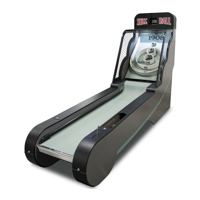
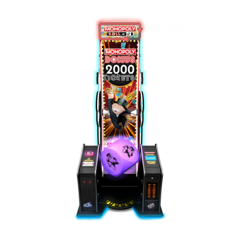
I.C.E Iceball Pro User manual

1
&
User Manual
Assembly Guide

2
Table of Contents
Safety…. Before you begin 3
Before you Begin 4
Assembly 5 - 12
Game Play 13
It won’t fit 14
Options 15
Diagnostic 16
Accessing Sensors 17
How to replace your sensors 18 - 19
How to access the electronics 20
How to replace the AC fuse 21
How to replace the electronics
+ 5 Supply 22
+12 Supply
Main board 23
How to replace your SDCARD
LED FUSE Protection - Fuse values 24
Wiring info 25
Warranty 26
Revision A - 11/18/20

3
WHEN INSTALLING THIS GAME, A GROUNDED A.C. RECEPTACLE MUST BE USED. FAILURE TO DO SO COULD RESULT IN
INJURY TO YOURSELF OR OTHERS. FAILURE TO USE A GROUNDED RECEPTACLE COULD ALSO CAUSE IMPROPER GAME
OPERATION, OR DAMAGE TO THE ELECTRONICS. THIS GAME IS DESIGNED TO DISSIPATE STATIC ELECTRICITY THROUGH
THE GROUNDING PLANE OF THE GAME. IF THE A.C. GROUND DOES NOT WORK, THE GAME COULD DISCHARGE STATIC
ELECTRICITY THROUGH THE GAME CIRCUITRY, WHICH COULD CAUSE DAMAGE.
DO NOT DEFEAT OR REMOVE THE GROUNDING PRONG ON THE POWER CORD FOR THE SAME REASON AS GIVEN
ABOVE. USING AN IMPROPERLY GROUNDED GAME COULD VOID YOUR WARRANTY.
IF YOU HAVE ANY QUESTIONS ABOUT YOUR OUTLET HAVE QUALIFIED ELECTRICIAN CHECK YOUR A.C. RECEPTACLE TO
BE SURE THE GROUND IS FUNCTIONING PROPERLY.
THE POWER SUPPLY IS NOT VOLTAGE ADJUSTABLE. TO OPERATE THE GAME AT VOLTAGES OTHER THAN THOSE IT WAS
DESIGNED FOR. PLEASE CONTACT OUR SERVICE DEPARTMENT FOR VOLTAGE CONVERSION INFORMATION.
DO NOT remove any of the components on the main board while the game is powered on. This may cause
permanent damage to the parts and the main board. Doing so will void the warranty of your game.
ALWAYS REMOVE POWER TO THE GAME, BEFORE ATTEMPTING ANY SERVICE, UNLESS NEEDED FOR SPECIFIC
TESTING.
FAILURE TO OBSERVE THIS PRECAUTION COULD RESULT IN SERIOUS INJURY TO YOURSELF OR OTHERS.
NOTE: THIS GAME IS INTENDED FOR INDOOR USE ONLY.
THIS GAME IS NOT SUITABLE FOR OUTDOOR USE OR WET ENVIROMENTS OR IN AREAS WHERE A WATER JET COULD BE
USED.
This game is not intended for use by persons (including children) with reduced physical, sensory or mental capabilies,
or lack of experience and knowledge, unless they have been given supervision or instrucon concerning use of this game
by a person responsible for their safety. Children should always be supervised when playing this game.
The games foot print is x x
WE RECOMMEND AT LEAST TWO ADULTS TO ASSEMBLY THIS GAME.
Watch the video on how to assembly at “https://youtu.be/Rby2KfknFAQ ”
AC Power Information
The games main fuse is accessed through the top of game and at the front.
Above the power cord is a small panel that contains the main fuse.
The value of the fuse for 120 volt users is 3 AMPS at 250Volt type slow blow.

4
Before you begin to assemble your game locate the parts below.
Ramp Assembly
AA6105
Latch tool
9 Balls
(color will vary)
Hardware
Front left side
Front right side
Back cabinet
PARTS BOX
If any parts are missing please contact ICE
Service at (716) 759-0360 Monday through
Friday 8:30 am to 6 pm Eastern Standard.
PC60601A
5/32 Allen
AA6001B
3/16 Allen
6 AA3052
Latch Hole plugs
Keys

5
Lay left side assembly so that the square holes are
facing up. Then insert the ramp assembly being
careful not to hold on from ramp end.
USE PROTECTIVE FOAM FROM PACKAGING TO
PROTECT SIDE CABINET DURING ASSEMBLY
DO NOT HOLD FROM HERE
Before inserting end into
side panel, ensure wire
harness is tucked safely in
channel.

6
Lift the cabinet half way up but not all the way to secure the two assemblies together.
Use one AA6211 Allen Bolt (1/4-20 X 1-1/4) and one 6212 washer where the two long square rods
went into the cabinet. A Allen wrench was provided in the parts package. Make sure inside supports
bars are fully inserted before tightening hardware.
You might have to push
the ramp down slightly so
that the side is flush to the
ramp assembly.

7
Put the cabinet back on its side and lift the right side assembly onto the runway/side assembly
aligning the supports into the square holes. You might have to flex the ramp end down to
allow the assemblies to be flush to each other.
Use one AA621 Allen Bolt (1/4-20 X 1-1/4) and one washer where the two long square rods went into
the cabinet. A Allen wrench was provided in the parts package.
Secure the ramp to the cabinet sides using two AA6211 Allen bolts
and two AA6070 large fender washers on each side.

8
Before flipping the cabinet right side up, connect the RGB harness from the support bar.
You made sure it was tucked into the square TUBE in Step 1 before you began assembly.
The cabinet uses cabinet latches to secure the back and front cabinets together. It will be
mush easier to assembly the two halves of the cabinets if you turn the latches 1/2 so that they
extend out a little. This is done using the latch tool provided in the parts box. The latches
have a decal showing a lock either locked or unlocked. Insert the latch tool in both latches and
only turn them 1/2 way as shown below.
½ out

9
Locate the clear plastic side panels, four PC60601 Allen bolts, four AA6212 washers, and four
AA6110 Joint Connectors.
On the outside of the cabinet insert four PC60601 Allen bolts with AA6212 washers shown in
the red arrows on the left. Do not insert one at the bottom. From the inside Insert the clear
plastic side panel and four AA6110 joint connectors. Use the 3/16 Allen wrench on the outside
and 5/32 Allen wrench on the inside to secure.
Repeat for the other side.
On the outside at the bottom insert one
PC60601 Allen bolt through the cabinet. Then
from the inside, install AR3502 bumper and
AA6110 joint connector. From the outside use
the 3/16 Allen wrench and the from the inside
use 5/32 Allen wrench to secure.
Repeat for the other side.

10
With help, move the front cabinet and
slide the latches into their mating
ends. Since they are 1/2 way out the
cabinet will remain against the front
cabinet until you latch them.
Insert the latch tool and turn it in the direction shown for lock. The decal is located on the backside
of the latch.
Insert a latch plug into the hole that you inserted
the latch tool into. If you ever need to remove the
two halves of the cabinet, use a small flat blade
screw driver to pry them back out.
Lock first!
Then Plug.

11
At either side and from underneath, connect the harnesses.

12
WARNING - ONLY PLUG INTO A GROUNDED OUTLET.
DO NOT USE ADAPTORS THAT ELIMINATE THE THIRD PRONG!
Insert the AC cord into a grounded AC outlet.
The cord can be found behind the back cabinet.
Locate the two keys in the parts box, insert them into
the top two locks, and turn clockwise to unlock.
The panel is hinged and will drop flat. Locate the AC
power module. Ensure the AC cord is plugged in.
Flip the AC switch to the on position. It will have a “I” label.

13
Your game is ready to be played. Press the “START” button to turn the game on. The game will
come to life. The cabinet will begin to glow and the upper display will come on.
There are five games and up to four players can play any of them. At anytime you can press either
the “GAME” button or “PLAYER” button. Pressing the “GAME” button will cycle through the
different games available. Pressing the player button will select how many players will play.
Once you have selected the game you wish to play and the amount of players that will play press
the “START” button to begin play.
** During game play, game volume can be adjusted by pressing the arrow keys. **
The classic alley roller game – throw 9 balls – score as many points as
possible. Player that scores the higher score wins.
Compete to get to zero first. For every ball thrown it subtracts from the
score. Be the first to reach 0 exactly to win!
Throw as fast but accurate to score more points with the “Time Bonus”.
Target the same hole with accuracy of the throw and with speed to score
the highest amount of points possible!
Bringing the classic dartboard game to ICE Ball Pro. Players hit
each hole three times. Player using the least amount of balls to
hit every hole three times wins!
Aim for the same hole. Hit the same hole 3 times in a row to win 3 time
bonus multiplier! Accuracy is key in this ICE Ball Pro classic game.

14
The back cabinet can be taken apart if it will
not fit through a doorway. The bottom and
top halves are held together with latches.
Lay the cabinet on it’s side.
REMOVE the Latch hole plugs.
Using the latch tool, unlock the four latches.
A decal shows the direction to unlock and
lock.
Pull the cabinet apart.
Use a small flat blade
screw driver to pry the
latch plugs out.

15
You can change some of the game options if you wish. Pressing the left and right arrows buttons
together will cause the game to display the options available for that game.
The arrow keys will change the value for that option displayed.
Pressing the “GAME” button will advance to the next option.
Pressing the “START” button will exit and save any changed you made.
Press the “GAME” button to select a different game and repeat this process.
The Game’s LED’s are controlled by the Accent color settings under Arcade. These are the only
options that effect all games. The remainder of the options are specific to that game only.
Accent Color 1 : Select LED color to light cabinet.
Accent Color 2 : Select LED color to light cabinet.
Accent Color 3 : Select LED color to light cabinet.
High Score Reset
• Min Off / Max On
• Default Off
Game Revision : Show version number.
High Score Reset
• Min = Off / Max = On
• Default Off
Game Revision: Show version number.
Number of balls per round:
• 1 or 3
• Default 3
High Score Reset
• Min Off / Max On
• Default Off
Game Revision : Show version number.
Starting Points
• 360 or 720
• Default: 320
High Score Reset
• Min = Off / Max = On
• Default Off
Game Revision: Show version number.
Number of balls per game
• 3, 6, or 9
• Default 9
High Score Reset
Min Off / Max On
Default Off
Game Revision : Show version number.

16
Diagnostic mode
0123456789ABCD
0 = 10 point sensor
1 = 40 point sensor
2 = right 100 point sensor
3 = N/A
4 = 20 point sensor
5 = N/A
6 = 30 point sensor
7 = N/A
8 = N/A
9 = Left 100 point sensor
A = player button
B = game button
C = up button
D = down button (it will always cause 0, 1, 2, 4, 6, and 9.)
E = Start
NOTE: Dropping a ball through 50 triggers 2 and 9.
When the game is in the standby mode, pressing and holding down the Down arrow button will
cause the game to enter a diagnostic mode. This mode will aid you in finding faults with your
game.
Once in the diagnostic mode, the game will play a sound file and display information on the status
of the buttons and score sensors.
The diagnostic will display any bad files found on the SDCARD with a letter, number, and or color.
If bad files exists, please contact ICE support for help in resolving any audio issues.
Score sensors can be tested by dropping a ball into each score hole. Test each by pressing each
button. The display will light a letter or number red when it detects a button press or a ball in a
score hole. See below for translation.

17
Lift the playfield out of the game and put aside.
Score sensors.
Remove the two bolts shown using a 5/32 Allen wrench.

18
10 hole
20 hole
30 hole
40 hole
WARNING! UNPLUG THE AC CORD FROM GAME BEFORE REPLACING SENSORS!
Follow the instructions in “Accessing score sensors” .
Each sensor is two boards with a harness that connects them together. The board with the
connection to the game’s harness is held in place by #2 Phillips screw. The other board is
attached with a standoff. The smaller board should be insert through the bottom cabinet holes
shown below and attached to the opposite side. When both are mounted to the cabinet, the
harness that connects the two should be underneath.
SCORE SENSORS 10, 20, 30 40

19
WARNING! UNPLUG THE AC CORD FROM GAME BEFORE REPLACING SENSORS!
Follow the instructions in “Accessing score sensors” .
Each sensor is two boards with a harness that connects them together. The board with the
connection to the game’s harness is held in place by #2 Phillips screw. The other board is
attached with a standoff. The boards are aligned straight across from each other.
LEFT AND RIGHT 100 SCORE SENSORS

20
Insert a key into both locks. Turn them clockwise to unlock.
The display assembly will open by dropping down.
+5 Power +12 Power
Mainboard
AC FUSE
Table of contents
Other I.C.E Arcade Game Machine manuals
Popular Arcade Game Machine manuals by other brands
NAMCO
NAMCO Prop cycle Operator's manual

Barron Games
Barron Games BG-X007 instruction manual

Sega
Sega The House Of The Dead 4 29"STD owner's manual

UNIS
UNIS JETBALL ALLEY G4K Operation manual

Barron Games
Barron Games MAGIC MUSHROOM & MINI BEAR owner's manual

Universal Space
Universal Space Squirt A Gator Operation manual

MD SPORTS
MD SPORTS AWH084 017E Assembly instructions

MD SPORTS
MD SPORTS FS048Y22002 Assembly instructions

MD SPORTS
MD SPORTS 24802 Assembly instructions

MD SPORTS
MD SPORTS CBF056 018M Assembly instructions

PlayMechanix
PlayMechanix Big Buck HD Setup and Operation Service Manual

MD SPORTS
MD SPORTS 1614823 Assembly instructions