manuals.online logo
Brands
  1. Home
  2. •
  3. Brands
  4. •
  5. i3 International
  6. •
  7. Security Camera
  8. •
  9. i3 International Ax63Z Series User manual

i3 International Ax63Z Series User manual

Other manuals for Ax63Z Series

2

Other i3 International Security Camera manuals

i3 International i3F416U User manual

i3 International

i3 International i3F416U User manual

i3 International Ax52 Series User manual

i3 International

i3 International Ax52 Series User manual

i3 International Am52RM User manual

i3 International

i3 International Am52RM User manual

i3 International Ax63Z Series User manual

i3 International

i3 International Ax63Z Series User manual

i3 International Ax52D2MV User manual

i3 International

i3 International Ax52D2MV User manual

i3 International Ax83C User manual

i3 International

i3 International Ax83C User manual

i3 International Am52 Series User manual

i3 International

i3 International Am52 Series User manual

i3 International ANNEXXUS Ax41V1MVR User manual

i3 International

i3 International ANNEXXUS Ax41V1MVR User manual

i3 International Ax40W2 series User manual

i3 International

i3 International Ax40W2 series User manual

i3 International C-AX401C1M User manual

i3 International

i3 International C-AX401C1M User manual

i3 International Ax47R series User manual

i3 International

i3 International Ax47R series User manual

i3 International C-AX401C1MN User manual

i3 International

i3 International C-AX401C1MN User manual

i3 International i3R363 User manual

i3 International

i3 International i3R363 User manual

i3 International Ax40W2 series User manual

i3 International

i3 International Ax40W2 series User manual

i3 International Ax32VD14 User manual

i3 International

i3 International Ax32VD14 User manual

i3 International Ax68R User manual

i3 International

i3 International Ax68R User manual

i3 International Am42 Series User manual

i3 International

i3 International Am42 Series User manual

i3 International Ax47R series User manual

i3 International

i3 International Ax47R series User manual

i3 International Ax47DC User manual

i3 International

i3 International Ax47DC User manual

i3 International M79 User manual

i3 International

i3 International M79 User manual

i3 International Ax46-series User manual

i3 International

i3 International Ax46-series User manual

i3 International Ax61 series User manual

i3 International

i3 International Ax61 series User manual

i3 International Ax85 User manual

i3 International

i3 International Ax85 User manual

i3 International Ax36 series User manual

i3 International

i3 International Ax36 series User manual

Popular Security Camera manuals by other brands

ADEMCO RapidDome Owners Operating & Installation Guide

ADEMCO

ADEMCO RapidDome Owners Operating & Installation Guide

EverFocus EBA2880 user manual

EverFocus

EverFocus EBA2880 user manual

Honeywell OptiCAM-IR Installation and setup guide

Honeywell

Honeywell OptiCAM-IR Installation and setup guide

Uniq UC-600 user manual

Uniq

Uniq UC-600 user manual

OPTICOM NVD-120-S datasheet

OPTICOM

OPTICOM NVD-120-S datasheet

Steren CCTV-221 instruction manual

Steren

Steren CCTV-221 instruction manual

Arm Electronics C420BCDNVFIR Features

Arm Electronics

Arm Electronics C420BCDNVFIR Features

Eneo PLD-2036PTZ installation guide

Eneo

Eneo PLD-2036PTZ installation guide

Axis AXIS M20 Series installation guide

Axis

Axis AXIS M20 Series installation guide

Panasonic KX-HCM230 operating instructions

Panasonic

Panasonic KX-HCM230 operating instructions

COP-USA CC15NV-SL Specifications

COP-USA

COP-USA CC15NV-SL Specifications

Active Silicon HARRIER H.264 quick start guide

Active Silicon

Active Silicon HARRIER H.264 quick start guide

Motorola Avigilon 1.3C-H5SL-BO1-IR installation guide

Motorola

Motorola Avigilon 1.3C-H5SL-BO1-IR installation guide

INSTEON 2864-232 user manual

INSTEON

INSTEON 2864-232 user manual

Wisenet XNB-6002 quick start guide

Wisenet

Wisenet XNB-6002 quick start guide

Axis M5525-E user manual

Axis

Axis M5525-E user manual

Vitek VTC-IR62NZ922 user guide

Vitek

Vitek VTC-IR62NZ922 user guide

Panasonic WV-SF342 Specifications

Panasonic

Panasonic WV-SF342 Specifications

manuals.online logo
manuals.online logoBrands
  • About & Mission
  • Contact us
  • Privacy Policy
  • Terms and Conditions

Copyright 2025 Manuals.Online. All Rights Reserved.

CAMERA PARTS AND DEFINITIONSSAFETY
When installing your Ax63Z camera be sure to avoid:
• excessive heat, such as direct sunlight or heating appliances
• contaminants such as dust and smoke
• strong magnetic fields
• moisture and humidity
• areas with mechanical vibrations
• fluorescent lamps or objects that reflect light and unstable light sources
• temperatures below -40° C (-40° F) and above 50° C (122° F).
To avoid electrical shock and to preserve the product warranty, DO NOT disassemble the
camera. Refer servicing to qualified personnel only.
POWER SUPPLY
This camera accepts PoE+ (IEEE 802.3at) or AC24V power for indoor installations.
Use AC24V power only for low-temperature outdoor installations.
Maximum power consumption for outdoor installations with heater on: 36W.
Ensure the supplied voltage meets the power consumption requirements of this camera
before powering the camera on. Incorrect voltage may cause irreparable damage to the
video camera and will effectively void the camera warranty.
CLEANING
• For maximum optical clarity, the camera dome or lens must remain clean. Use a soft,
dry cloth to remove finger prints or dust from the dome cover.
• Use a blower to remove dust from the lens.
• Do not use volatile solvents such as alcohol, benzene, or thinners, as they may dam-
age the surface finishes.
1. 1.5” Female coupler. Remove when using with
i3D702 and i3D703 brackets and replace with
1.5” Male coupler (provided, “A”).
2. Drop protection/safety wire. Secure to a solid
surface during installation to prevent accidental
camera drop.
3. Main signal connector.
4. RJ45 Ethernet PoE+ Port. Connect to the network
switch. Use RJ Female/Female coupler (E) if
needed. Camera supports PoE+ power in indoor
installations.
5. AC24V Power Connector (Black/White). Connect to
a power supply. Make sure to connect the terminals
to correct ports. (Black+/White-). Do not use if
installing indoors and using PoE+ power.
3MP High-Speed Network Dome Camera
Ax63Z
User Manual
i3-TRNG-CAMS-Ax63Z.indd
Rev. 200113
QR Code for Complete
User Manual and ACT
Scan this QR code or visit ftp.i3international.com to view and
download AnnexxusConfigurationTool v1.5 (ACT) and the full
User Manual.
Contact our Technical Support team at: 1.877.877.7241 or
[email protected] if you have any questions or
concerns regarding camera installation or if you require software
services or support.
5
9
10
11
14 3/16” (360.19mm)
3.7” (94mm)
8.5” (216.14mm)
R3.45”
(88.5mm)
2
3
8
12
4
6
7
Alarm In: 5 (Blue); 6 (Green); GND (White)
Alarm In: 1 (Red); 2 (Brown)
Alarm In: 3 (Yellow); 4 (Orange)
Factory Default (Pink/Gray)
Audio In (Black/White)
Restart (Orange/White)
Alarm Out: Open (Light Green);
COM (Black); Closed (Purple)
RJ45: Ethernet, PoE+
AC24V Power
(Black/White)
PACKAGE CONTENTS
Ensure that the items received match those listed on the order form and the packing slip.
In addition to this manual and a fully assembled camera, the dome camera packing box
includes:
A. 1.5” Male coupler x1
(Use with i3D702 and i3D703 PTZ brackets)
B. Blind set screw x1
C. Hex driver (Allen key) x1
D. Security driver (Torx key) x1
E. RJ45 Female/Female coupler x1
B C D E
A
MOUNTING OPTIONS
Compatible i3 Mounting Accessories:
i3D702 - Pendant Surface Pipe mount bracket. Use 1.5” Male Coupler (A).
i3D703 - Wall Mount bracket. Use 1.5” Male coupler (A).
i3D704 - Junction Box Gooseneck Wall Mount 1.5” NTP bracket
i3D705 - Junction Box Pendant Wall Mount 1.5” NTP bracket
i3D706 - Parapet Mount 1.5” NTP bracket
i3D707 - Corner Mount for i3D703
i3D708 - Pole Mount for i3D703
i3D709 - Pipe Extension 1.5” NTP
i3D710 - Sunshield Hood
Mounting Type Additional Accessories required
Horizontal Wall Mount i3D703 or i3D704
Parapet Mount i3D706
Pendant Mount i3D702 or i3D705
Corner Mount i3D703 + i3D707
Pole Mount i3D703 + i3D708
6. Restart (Orange/White). Use jumper cable to short two PIN connectors for 10 seconds
to restart Ax63Z.
7. Audio In (Black/White). Connect to an external audio input device (microphone) to
record audio stream with video.
8. Alarm Out (Light Green - Open; Black - COM, Purple - Closed). Connect to the alarm
out device (speaker, strobe light, etc.)
9. Alarm In 1-2 (Red - #1, Brown - #2). Connect to the alarm in device (motion
detector, temperature sensor, etc.)
10. Alarm In 3-4 (Yellow - #3, Orange - #4). Connect to the alarm in device.
11. Alarm In 5-6 (Blue - #5, Green - #6, White - GND). Connect to the alarm in device.
12. Factory Default (Pink/Gray). Use jumper cable to short two PIN connectors for 10
seconds to return Ax63Z to factory defaults.
1
Ax63Z High-Speed Dome
QUICK START GUIDE
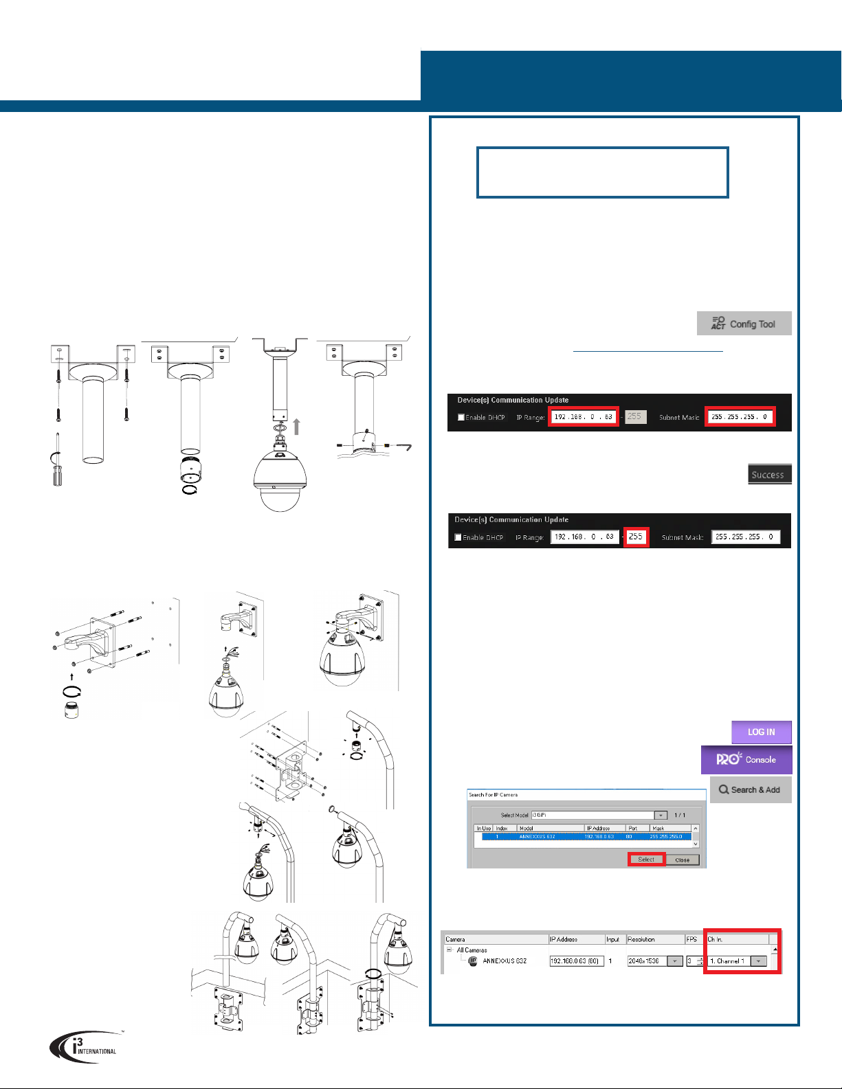
CONNECT CAMERA TO i3 SRX-PRO SERVER
Camera’s default IP address: 192.0.0.16.
Camera’s default Subnet mask address: 255.255.255.0.
Credentials*: Login - i3admin / Password - i3admin
*Important: For the security of your camera and of all connected devices,
i3 International recommends that you change your camera’s default administrative
password in the camera’s User Management setup tab. Keep your passwords
secure.
Change your Annexxus camera’s default IP Address:
Annexxus Cameras cannot share an IP address, each camera requires its own
unique IP address.
1. Connect your Annexxus camera to the Gigabit switch.
2. On your i3 NVR, launch i3 Annexxus Configuration Tool (ACT). ACT can be
accessed from the Windows Start menu or from the IP
Camera setup tab (ACT Config Tool button)
You can download and install the latest ACT installation
package from i3 website: https://i3international.com/download
3. Select your Annexxus camera in the ACT list.
4. Enter the new IP address and Subnet Mask of the camera in the Device(s)
Communication Update area.
5. Click Update and then Yes in the confirmation window.
Tip: New IP address must match the IP range of LAN or NVR’s NIC1.
6. Wait a few moments for a “Success” message in the Result field.
Repeat Steps 1-6 for all detected Annexxus cameras OR
7. Assign IP range to multiple cameras by selecting two or more cameras in ACT,
then entering the starting IP address and the final IP octet for your IP range.
8. Click Update and then Yes in the confirmation window.
Wait until “Success” message is shown for all selected cameras.
Ensure you can connect to your camera(s) using its new IP Address:
1. Open an Internet browser window and enter the new IP Address you have just
assigned to your Annexxus camera in Step 4 (or 7).
2. Enter the camera User Name and Password in the pop-up login window.
3. Annexxus camera interface will be displayed in the Internet Explorer window.
You should be able to see the camera image on the screen. If you do not see
the camera image on the screen, call i3 International technical support team
for troubleshooting tips: 1.877.877.7241
Add your Annexxus camera to IP Camera tab in SRX-Pro Server:
1. (SRX-Pro Service Users) Click LOG IN in SRX-Pro Service
Monitor, enter your credentials and click LOGIN.
2. Click PRO Console button to launch Pro Console.
3. Go to Setup -> IP Camera tab.
4. Click the Search & Add button to display connected
Annexxus cameras.
5. Select the detected camera in the list and click Select.
6. In the Select IP Camera window, enter camera’s User Name and Password and
click Add.
Selected camera will be added to the Camera list.
7. Assign the camera to the SRX-Pro video channel in the Ch In. column.
Your Annexxus camera is now connected to SRX-Pro Server and is ready to record.
Change resolution and frame rate for the Annexxus camera in the IP Camera tab
menu or via Web Setup.
i3 INTERNATIONAL INC. 1.866.840.0004
www.i3international.com
WALL MOUNT
1. Mount the i3D703 Wall Mount bracket to the wall. Use appropriate mounting hardware
(not provided).
2. Remove the 1.5” Female coupler from the camera and attach the 1.5” Male coupler
(E) to the end of the Wall Mount bracket by rotating clockwise.
3. Thread all cables through the bracket and out of the opening on the back of the
bracket.
4. Use hex key to secure set screw to connector ring and fasten safety cable.
PARAPET WALL MOUNT
1. Mount the i3D702 Pendant Pipe bracket to a ceiling surface. Use appropriate
mounting hardware (not provided).
2. Remove the 1.5” Female coupler from the camera and attach the 1.5” Male coupler
(E) to the end of the pendant pipe by rotating clockwise.
3. Thread all cables through the pipe and out of the top opening of the bracket.
4. Use hex key to secure set screw to connector ring and fasten safety cable.
PENDANT PIPE MOUNT
INSTALLATION
1. Remove the dome cover using the Torx key (D).
2. Remove the protective foam from the lens assembly.
3. Re-attach dome cover.
4. Mount the camera (basic options presented below).
5. Connect the camera to Alarm In/Out and Audio In devices, if using.
6. Connect the camera to a AC24V power source for outdoor installations or PoE+ switch
for indoor installations.
(For reliable PoE+ power, use i3 switches S81, S242, S243, or S244).
7. If using AC24V power, connect the camera to a PoE+ switch, then connect the switch
to the IP CAMERA RJ45 port on the back of the i3 NVR.
1. Mount the i3D706 Parapet
Mount bracket to the
parapet. Use appropriate
mounting hardware (not
provided).
2. Attach the camera’s 1.5”
Female coupler to the
end of the Parapet Mount
pipe bracket by rotating
clockwise
3. Thread all cables through
the bracket and out of the
opening on the other end of
the mount pipe.
4. Use hex key to secure set
screw to connector ring and
fasten safety cable.
5. Insert entire tube including
main unit into hole fitting on
secure plate
6. Rotate tube 180 degrees
clockwise with secure plate
and fasten screws.