6
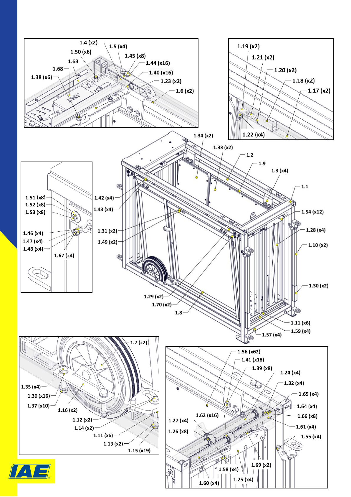
BOM ID PART_NO IAE_DESCRIPTION
1.1 1002452 3 Way Draer Outer Crate
1.2 1002470 3 Way Draer Inner Cage
1.3 1002551 HR SHT 8 90X62X102 Profiled BTF
1.4 1002806 Load Cell T85-N-300kg 500mm Cable
1.5 1002552 HR SHT 5 50X30 Profiled
1.6 1002557 Load Cell T85-N-300kg 1650mm Cable
1.7 B152 1102 80 Blickle 250mm Polypro Wheel c/w RT
1.8 1002503 3 Way Draer LH Side Door
1.9 1002509 3 Way Draer RH Side Door
1.10 1002499 Lamb Weigher Transport Handles
1.11 1002446 180OD 8.4ID 30L Nylon Spacer
1.12 B003 3080 80 M8 X 80 Bolt BZP
1.13 B041 3001 08 M8 Washer Form A BZP
1.14 B041 3007 08 M8 Repair Washer (Form G)
1.15 B040 3002 08 M8 Full Nyloc Nut Type T BZP
1.16 1002564 3 Way Draer Axle
1.17 1002545 RND BRT 16 715L HoleX1 Chamfer End
1.18 1002542 21X45X81 HDPE Block 3XHoles
1.19 1002546 Sliding Bolt Housing
1.20 B051 3050 20 5X20 Selloc Pin BZP
1.21 1002544 Compression Spring 19.75OD 76L 1.63 Wire
1.22 B052 6048 00 4.8X10 STL Dome Head Mul-Grip Rivet
1.23 1002512 3 Way Draer Sliding Door Top Channel
1.24 1002527 RND BRT 16 559L Tapped Both Ends
1.25 1002522 3 Way Draer Sliding Door Carriage
1.26 1002810 LME16UU Neutral Metric Linar Ballbushing
1.27 1002528 HR SHT 4 25X202.5 Profiled
1.28 1002515 3 Way Draer Sliding Gate
1.29 B041 2006 12 M12 Washer (Form F) Galv
1.30 B107 0002 50 25mm Blue Textured Hand Grip
1.31 1002543 Ø10.5ID Ø20OD 2mm Nylon Washer
1.32 1002536 6X32X10 U Groove Bearing Pulley
1.33 1002567 8X815X715 Smooth Stockboard
1.34 1002568 8X828X332 Smooth Stockboard
1.35 B003 3100 60 M10 X 60 Bolt BZP
1.36 B041 3050 10 M10 Washer (Form E)
1.37 B040 3002 10 M10 Full Nyloc Nut Type T BZP
1.38 B009 3100 60 M10 X 60 Cup Square Bolt BZP
1.39 B003 3120 60 M12 X 60 Bolt BZP
1.40 B040 3002 12 M12 Nyloc Nut Type T BZP
1.41 B041 3006 12 M12 Washer (Form F) BZP
1.42 B041 3302 12 M12 Spring Washer Type B BZP
1.43 B001 3120 30 M12 X 30 Setscrew BZP
1.44 B041 3020 12 M12 Washer Form B BZP (24X13X1.6)
1.45 B003 3120 65 M12 X 65 Bolt BZP
1.46 1002534 Compression Spring 10OD 18.4L 1.58 Wire
1.47 B041 3001 06 M6 Washer (Form A)
1.48 B040 3002 06 M6 Nyloc Nut Type T BZP
1.49 B001 3100 25 M10X25 Setscrew BZP
1.50 B040 3034 10 M10 CSKHead Part Hex Insert Nut 0.8-4 GR
1.51 1002529 M6 Washer (Mudguard) 25Ø BZP
1.52 B041 3302 06 M6 Spring Washer Type B BZP
1.53 B001 3060 20 M6X20 Setscrew BZP
1.54 B029 3080 25 M8X25 Socket Buon Head Screw BZP
1.55 B003 3080 55 M8X55 Bolt BZP
1.56 B021 3551 19 5.5X19mm Pan HD (Phillips) Drill Screw
1.57 B003 3100 75 M10 X 75 Bolt BZP
1.58 B115 1025 12 25 X 25 X 1-2W BLK Plasc Insert 5960
1.59 B050 3125 40 1/8 X 1IN Coer Pin BZP
1.60 1002600 545mm 7X7 Wire Rope Assy. So Eyes
1.61 B040 3002 05 M5 Nyloc Nut BZP
1.62 1002606 28mm External Circlip
1.63 1002549 DX51 SHT 1.2 149X51X350 Profiled BTF
1.64 1002535 CR SHT 2 15X16X32.5 Formed Bracket
1.65 B001 3060 25 M6X25 Setscrew BZP
1.66 B041 3001 05 M5 Washer Form A BZP
1.67 B001 3060 40 M6 X 40mm Setscrew BZP
1.68 1002558 JB4T-PG9 Juncon Box
1.69 1002533 EXT Spring Ø22.75 167L 1.5W
1.70 B115 7060 21 Grommet Foot 6.0mm X 2.1mm
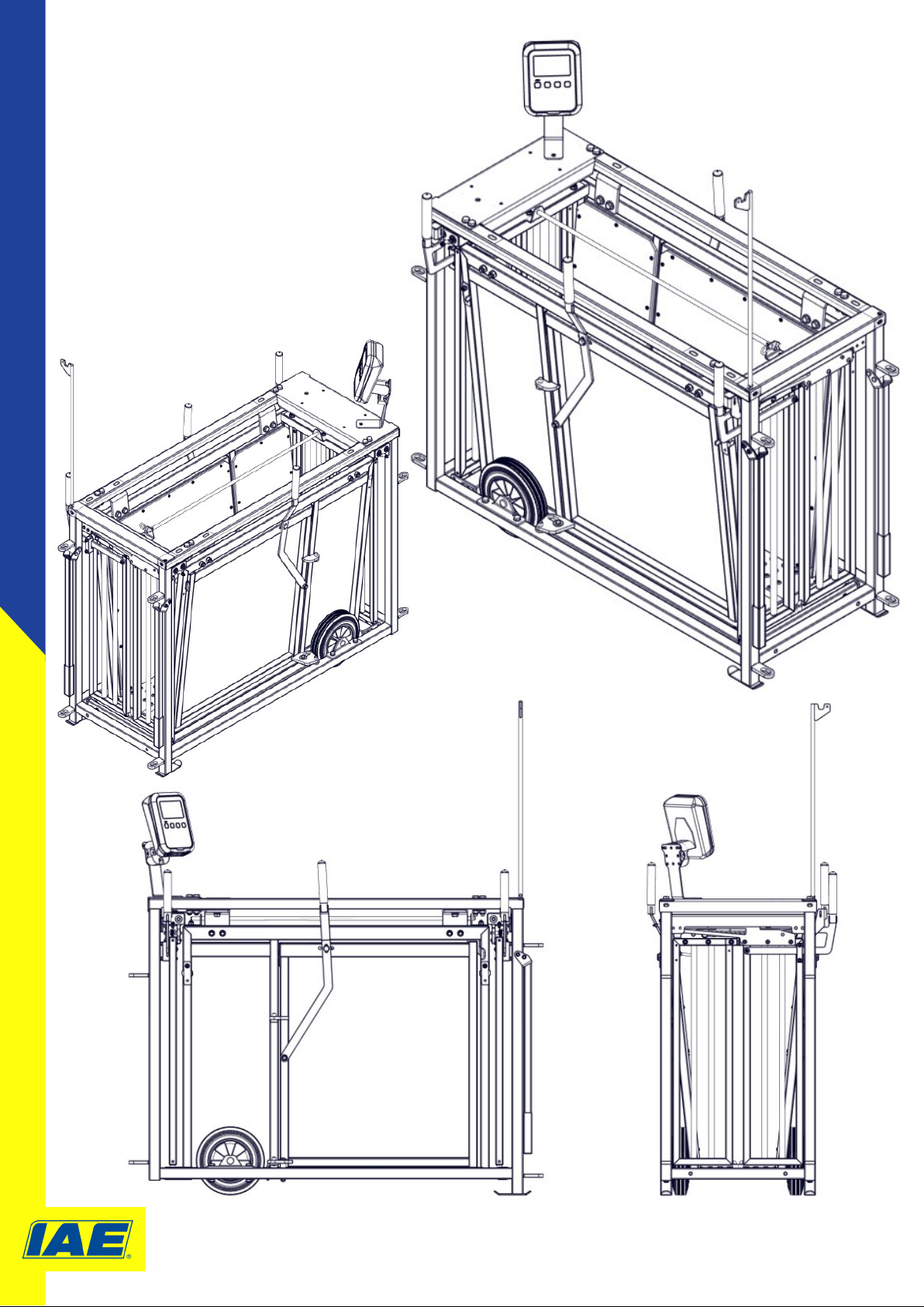
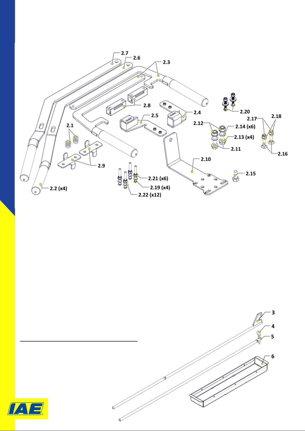
Parts List DraMaster Main Body
Product Code 1002451-01
Reference page 5 for illustraons