2
WA-1000D-CL
Contents
Notice............................................................................3
Warranty .......................................................................3
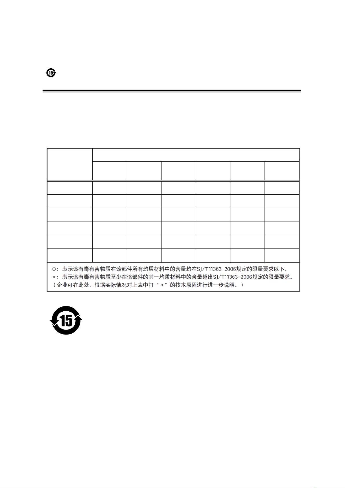
Certifications.................................................................3
Warning ........................................................................3
Usage Precautions .......................................................5
Features........................................................................6
Parts Identification ........................................................7
Preparation........................................................... 11
Preparation Flow.........................................................11
Step 1: Installing the Software (first time only)............11
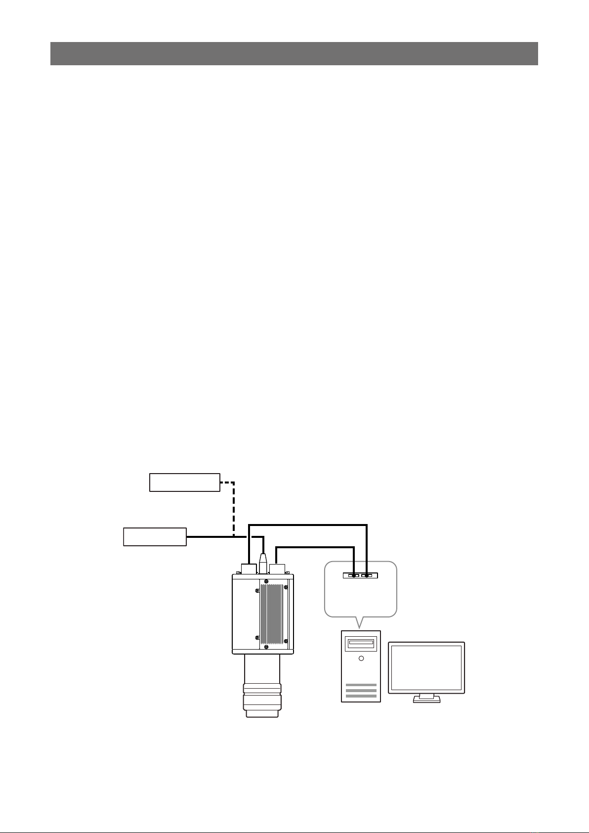
Step 2: Connecting Devices........................................13
Step 3: Verifying the Camera Connection Status........15
Step 4: Configuring Basic Settings for the Camera ....15
Connecting to the Camera to Control Tool .............15
Configuring the Output Format...............................15
Control via External Triggers.......................................16
When Controlling the Exposure Time Using
Specified Exposure Times......................................16
When Controlling the Exposure Time Using
the Pulse Width of the Trigger Input Signal ............16
Control Without External Triggers ...............................17
When Controlling the Exposure Time Using
Specified Exposure Times......................................17
When Not Controlling the Exposure Time...............17
Step 5: Adjusting the Image Quality............................18
Step 6: Configuring Various Other Settings ................18
Step 7: Saving the Settings.........................................18
To save user settings ..........................................19
To load user settings...........................................19
Basic Function Matrix .................................................20
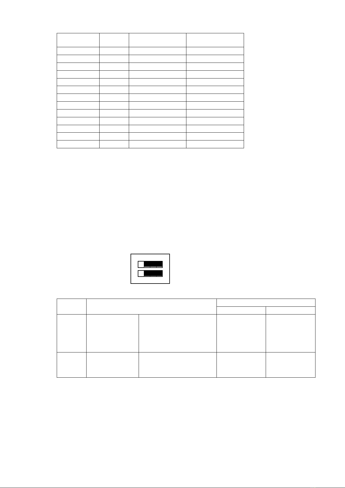
Operation modes and One Push channel balance
(WB) operations .............................................20
Main Functions .................................................... 21
Camera Output Formats .............................................21
Camera Link Output Ports ......................................21
2-ch.....................................................................21
Dual base ...........................................................21
Camera Link Bit Assignments ................................22
Video Output Timing Diagram ............................23
Exposure Mode...........................................................24
Image Output Timing ..................................................24
Horizontal Timing....................................................24
When [Exposure Mode] is [Off]
(internal trigger) .............................................24
Trigger Control ............................................................24
Shortest Repetition Period for Triggers...................25
Shortest Trigger Pulse Width ..................................25
When [Exposure Mode] is [Off] ..........................25
When [Exposure Mode] is [Timed].....................26
When [Exposure Mode] is [Trigger Width] .........27
During normal continuous operation ..................27
Pixel Sensitivity Correction .........................................29
PRNU Correction ....................................................29
DSNU Correction ....................................................29
Defective Pixel Correction...........................................29
Auto detection function.......................................29
Gain Control................................................................30
Sensor conversion gain ......................................30
Analog base gain ...............................................30
Analog fine gain..................................................31
LUT (Lookup Table) / Gamma Function......................31
γ0.45 ..................................................................32
LUT .....................................................................32
Shading Correction.....................................................32
Flat shading correction.......................................32
To perform the shading function.........................33
Channel Balancing......................................................33
Gain channel balancing .....................................33
Shutter channel balancing (Exposure Mode
Timed only) ....................................................33
Black Level Correction................................................33
Variable Line Rate ......................................................33
Auto line rate configuration function...................34
Electronic Shutter .......................................................34
EEN (Exposure Enable) Function...............................34
Test Pattern Function..................................................35
1: Gray 1 .............................................................35
2: Gray 2 .............................................................35
3: White (890LSB)...............................................35
RS-232C Command Control.......................................36
Field Upgrade Function ..............................................36
Settings List......................................................... 37
Control Tool.................................................................37
Communication...........................................................40
Miscellaneous...................................................... 41
Troubleshooting ..........................................................41
Specifications..............................................................42
Block Diagram.............................................................45
Spectral Response .....................................................46
Dimensions.................................................................47
Index ..................................................................... 49