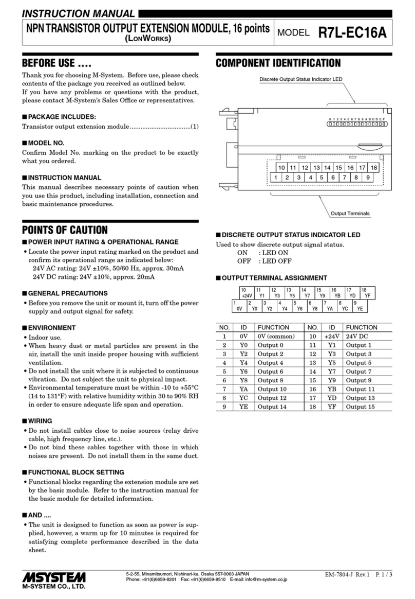
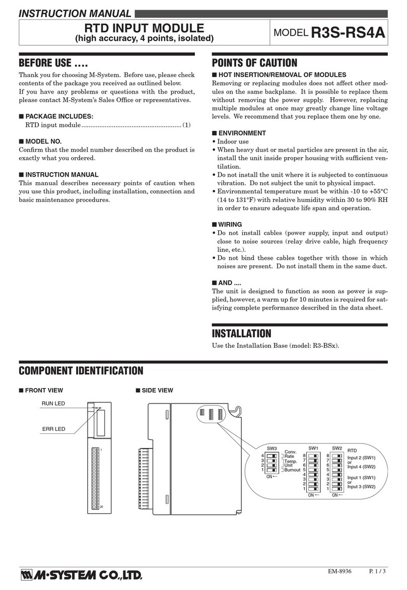
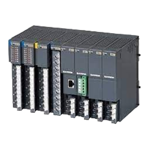
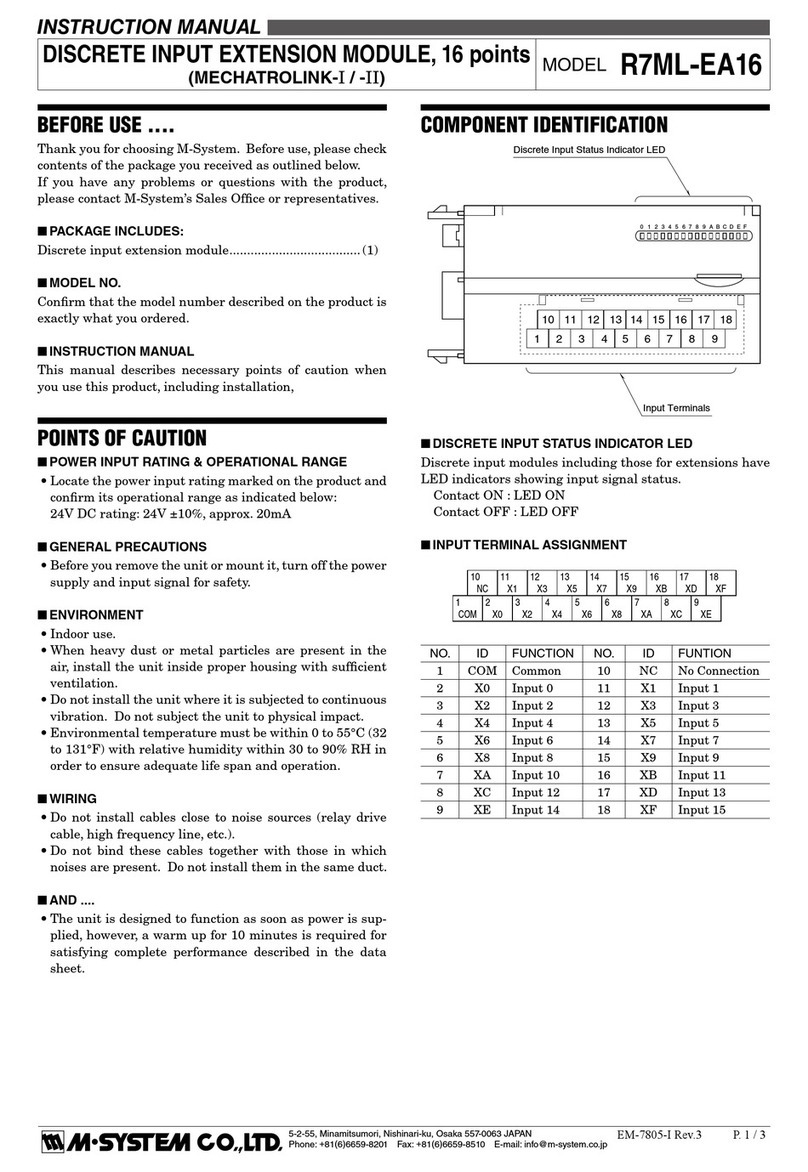
manuals.online logo
Brands
  1. Home
  2. •
  3. Brands
  4. •
  5. M-system
  6. •
  7. Control Unit
  8. •
  9. M-system R3-AS4 User manual

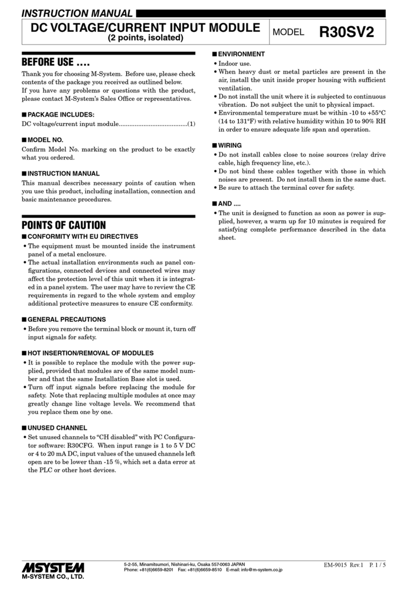
M-system R3-AS4 User manual

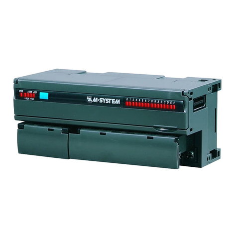
R3-AS4
P. 1 / 3 EM-8439 Rev.1
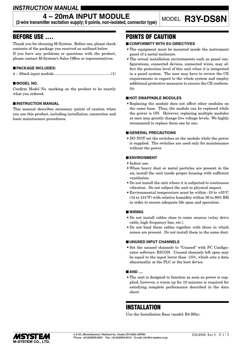
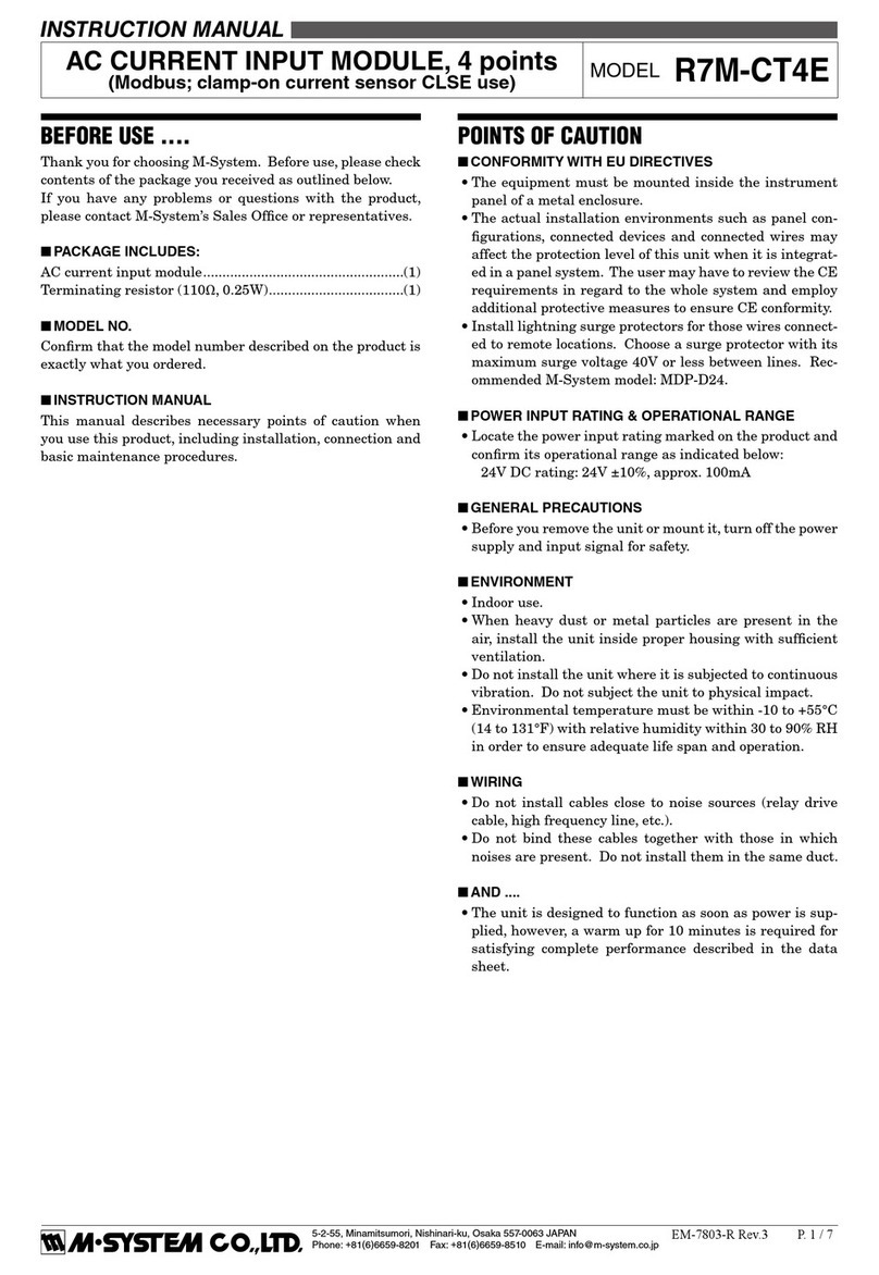
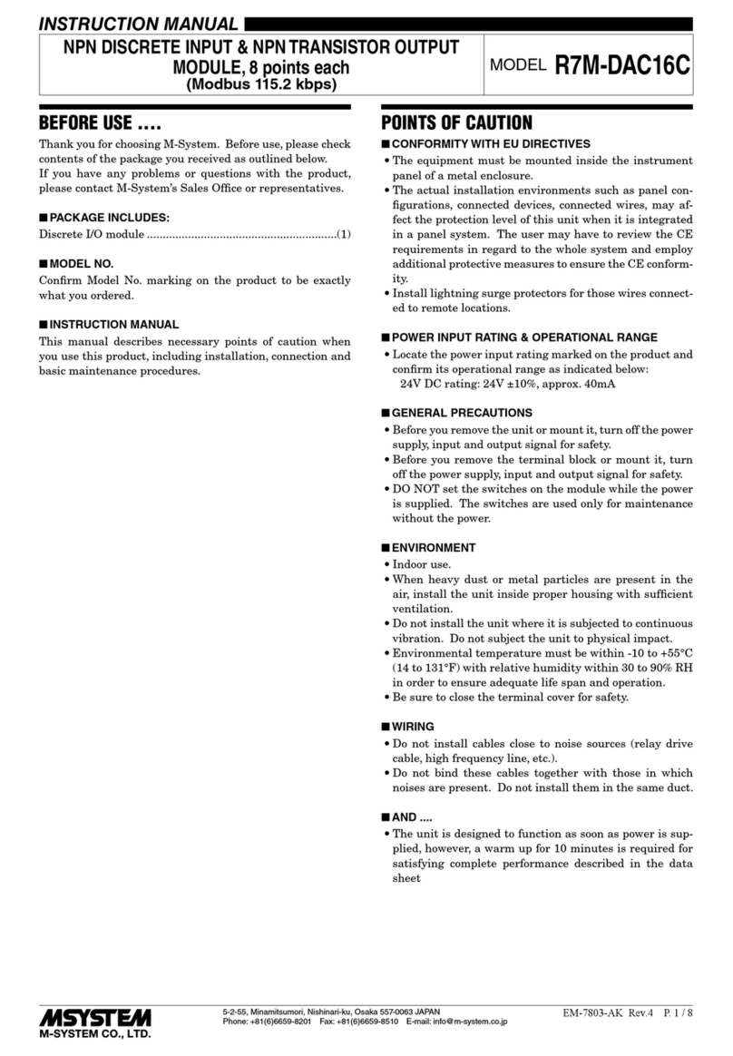
BEFORE USE ....
Thank you for choosing M-System. Before use, please check
the contents of the package you received as outlined below.
If you have any problems or questions with the product,
please contact M-System’s Sales Office or representatives.
■ PACKAGE INCLUDES:
DC current input alam module .................................. (1)
■ MODEL NO.
Check that model No. described on the specification label is
exactly what you ordered.
■ INSTRUCTION MANUAL
This manual describes necessary points of caution when you
use this product, including installation, connection and basic
maintenance procedures.
INSTRUCTION MANUAL
MODEL R3-AS4
DC CURRENT INPUT ALARM MODULE
(4 points, isolated)
POINTS OF CAUTION
■ CONFORMITY WITH EC DIRECTIVES
• The equipment must be mounted inside the instrument
panel of a metal enclosure.
• The actual installation environments such as panel con-
figurations, connected devices and connected wires may
affect the protection level of this unit when it is integrated in
a panel system. The user may have to review the CE
requirements in regard to the whole system and employ
additional protective measures to ensure CE conformity.
■ HOT INSERTION/REMOVAL OF MODULES
Removing or replacing modules does not affect other modules
on the same backplane. It is possible to replace them without
removing the power supply. However, replacing multiple
modules at once may greatly change line voltage levels. We
recommend that you replace them one by one.
■ ENVIRONMENT
• Indoor use
• When heavy dust or metal particles are present in the air,
install the unit inside proper housing with sufficient ventila-
tion.
• Do not install the unit where it is subjected to continuous
vibration. Do not subject the unit to physical impact.
• Environmental temperature must be within -10 to +55°C
(14 to 131°F) with relative humidity within 30 to 90% RH in
order to ensure adequate life span and operation.
■ WIRING
• Do not install cables (power supply, input and output) close
to noise sources (relay drive cable, high frequency line, etc.).
• Do not bind these cables together with those in which noises
are present. Do not install them in the same duct.
■ UNUSED INPUT CHANNELS
• Set the unused input channels to ±20mA or 0 – 20mA range.
Unused channels left open with 4 – 20mA setting are equal
to the input lower than -15%, which sets a data abnormality
at the PLC or the host device.
Open circuit with the input range set to ±20mA means 50%
of the full-scale. An alarm setpoint must be set to a value
that does not trip an unwanted alarm.
• Unused channels can be specified and set so on the PC
Configurator Software (model: R3CON) without needing the
above mentioned setting.
■ AND ....
• The unit is designed to function as soon as power is
supplied, however, a warm up for 10 minutes is required for
satisfying complete performance described in the data sheet.
INSTALLATION
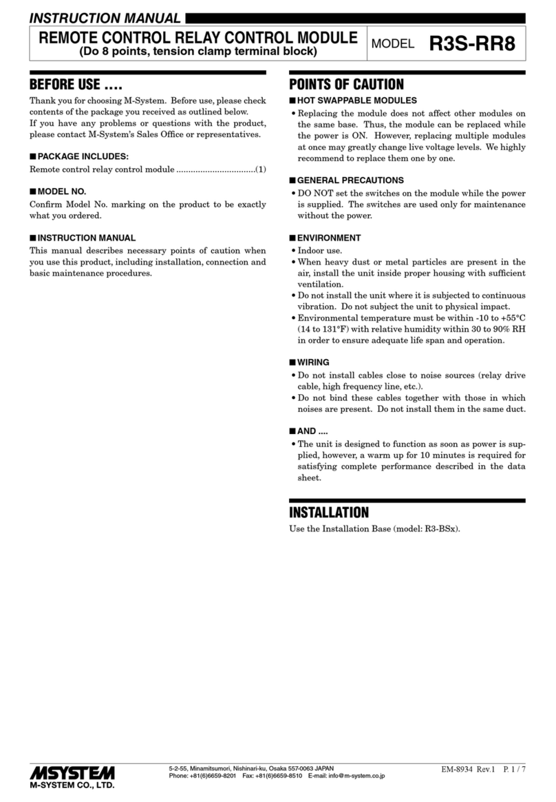
Use the Installation Base (model: R3-BSx).
R3-AS4
P. 2 / 3 EM-8439 Rev.1
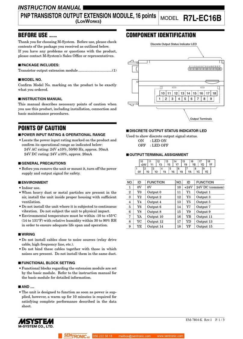
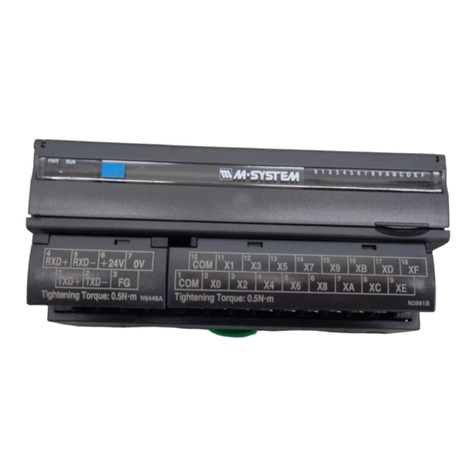
COMPONENT IDENTIFICATION
•Conversion Rate: SW3
SW CONVERSION RATE
80 ms (*)40 ms 20 ms 10 ms
SW3-1 OFF ON OFF ON
SW3-2 OFF OFF ON ON
(*) Factory setting
1
11
12
13
14
15
16
17
18
19
20
2
3
4
5
6
7
8
9
10
ON
8
7
6
5
4
3
2
1
SW1SW2
ON
8
7
6
5
4
3
2
1
SW3
ON
4
3
2
1
■FRONT VIEW ■SIDE VIEW
ERR LED
RUN LED
Conv.
Rate
Input 2 (SW1)
or
Input 4 (SW2)
Range
Input 1 (SW1)
or
Input 3 (SW2)
■SIDE DIP SW
•Input Range: SW1, SW2
INPUT 1 (SW1) INPUT 2 (SW1)
INPUT 3 (SW2) INPUT 4 (SW2) RANGE
12345678
OFF OFF OFF OFF OFF OFF OFF OFF
4 – 20mA
(*)
ON OFF OFF OFF ON OFF OFF OFF 0 – 20mA
OFF ON OFF OFF OFF ON OFF OFF
-20 – +20mA
OUTPUT DATA DESCRIPTIONS
Four alarm setpoints are selectable per each input. One (1)
word (16 bit) data is transmitterd to the PLC or the host
device via the R3 network module.
0
15
Alarm 1
Alarm 2 Input 1
Alarm 3
Alarm 4
Alarm 1
Alarm 2 Input 2
Alarm 3
Alarm 4
Alarm 1
Alarm 2 Input 3
Alarm 3
Alarm 4
Alarm 1
Alarm 2 Input 4
Alarm 3
Alarm 4
ALARM SETTING
The following parameters are programmable using the PC
Configurator Software (model: R3CON).
■ALARMTRIP POINT (-15.00 to +115.00%)
Four alarm setpoints are selectable per each input.
■ALARM TYPE (High or Low)
High or Low alarm is selectable for each alarm trip point.
High alarm: An alarm is set when the input signal goes above
the setpoint.
Low alarm: An alarm is set when the input signal goes be-
low the setpoint.
■DEADBAND (HYSTERESIS)
(0.00 to 100.00%; factory set to 5.00)
Deadband (deviation between the points where the alarm is
set and reset) is selectable for each alarm trip point.
■POWER ON DELAY TIME
(0.0 to 99.0 seconds; factory set to 5.0)
The alarm output start functioning in the preset time after
the power has been turned on.
This setting is common to all four points.
■ALARM ON DELAYTIME
(0.0 to 99.0 seconds; factory set to 1.0)
The alarm output is set when the preset time elapses after
the input has entered in the alarm range.
This setting is common to all four points.
■ALARM HOLD TIME
(0.0 to 99.0 seconds; factory set to 1.0)
The alarm output is held for the preset time even if it is
reset in shorter time.
This setting is common to all four points.
■STATUS INDICATOR LED
RUN indicator: Bi-color (red/green) LED;
Red when the bus A operates normally;
Green when the bus B operates normally;
Amber when both buses operate normally.
ERR indicator: Bi-color (red/green) LED;
Red with the input abnormality;
Green in normal operating conditions.
R3-AS4
P. 3 / 3 EM-8439 Rev.1
■ DIMENSIONS mm (inch)
■ CONNECTION DIAGRAM
TERMINAL CONNECTIONS
Connect the unit as in the diagram below.
M-SYSTEM WARRANTY
M-System warrants such new M-System product which it manufactures to be free from defects in materials and workmanship during the 36-month period following the date that such
productwasoriginallypurchasedifsuchproducthasbeenusedundernormaloperatingconditionsandproperlymaintained,M-System'ssoleliability,andpurchaser'sexclusiveremedies,
under this warranty are, at M-System's option, the repair, replacement or refund of the purchase price of any M-System product which is defective under the terms of this warranty. To
submit a claim under this warranty, the purchaser must return, at its expense, the defective M-System product to the below address together with a copy of its original sales invoice.
THIS IS THE ONLY WARRANTY APPLICABLE TO M-SYSTEM PRODUCT AND IS IN LIEU OF ALL OTHER WARRANTIES, EXPRESS OR IMPLIED, INCLUDING ANY IMPLIED
WARRANTIES OF MERCHANTABILITY OR FITNESS FOR A PARTICULAR PURPOSE. M-SYSTEM SHALL HAVE NO LIABILITY FOR CONSEQUENTIAL, INCIDENTAL OR
SPECIAL DAMAGES OF ANY KIND WHATSOEVER.
M-System Co., Ltd., 5-2-55, Minamitsumori, Nishinari-ku, Osaka 557-0063 JAPAN, Phone: (06) 6659-8201, Fax: (06) 6659-8510, E-mail: [email protected]
WIRING INSTRUCTIONS
■SOLDERLESS TERMINAL mm (inch)
Refer to the drawing below for recommended ring tongue
terminal size. Spade tongue type is also applicable. Solderless
terminals with insulation sleeve do not fit. Applicable wire
size: 0.3 – 0.75 mm2
3.2 (.13) dia.
4 min.
(.16)
12 (.47) max.
6 max.
(.24)
3 (.12) max.
1
11
12
13
14
15
16
17
18
19
20
2
3
4
5
6
7
8
9
10
130 (5.12)
27.5 (1.08) 109 (4.29) POSITIONING
GUIDE
TERMINAL
COVER
20–M3
SCREW
6.2
(.24)
1
2
–
INPUT 1
+
INTERNAL POWER
BUS A
BUS B*
*For dual redundant communication.
BUS CONNECTOR
3
4
–
INPUT 2
+
6
7
–
INPUT 3
+
8
9
–
INPUT 4
+

Other M-system Control Unit manuals

M-system R30CT4E User manual

M-system

M-system R30CT4E User manual

M-system R7C-TS4 User manual

M-system

M-system R7C-TS4 User manual

M-system R3-PD16B User manual

M-system

M-system R3-PD16B User manual

M-system R7D-EA8 User manual

M-system

M-system R7D-EA8 User manual

M-system R3-NC2 User manual

M-system

M-system R3-NC2 User manual

M-system R3-ND1 User manual

M-system

M-system R3-ND1 User manual

M-system R1M-A1 User manual

M-system

M-system R1M-A1 User manual

M-system R3-NEIP1 User manual

M-system

M-system R3-NEIP1 User manual

M-system R7C-DC16A User manual

M-system

M-system R7C-DC16A User manual

M-system R3-PA8 User manual

M-system

M-system R3-PA8 User manual

M-system R7M-TS4 User manual

M-system

M-system R7M-TS4 User manual

M-system R7E-DA16 User manual

M-system

M-system R7E-DA16 User manual

M-system R7L-YS2 User manual

M-system

M-system R7L-YS2 User manual

M-system 61F User manual

M-system

M-system 61F User manual

M-system R8-SVT8 User manual

M-system

M-system R8-SVT8 User manual

M-system R7C-EC8A/UL User manual

M-system

M-system R7C-EC8A/UL User manual

M-system R7L-YV2 User manual

M-system

M-system R7L-YV2 User manual

M-system R3Y-SV16 User manual

M-system

M-system R3Y-SV16 User manual

M-system M6DXF1 User manual

M-system

M-system M6DXF1 User manual

M-system R7F4HML3-D-DAC32B User manual

M-system

M-system R7F4HML3-D-DAC32B User manual

M-system Devicenet R7F4HD-DAC32D User manual

M-system

M-system Devicenet R7F4HD-DAC32D User manual

M-system R3-NC1 User manual

M-system

M-system R3-NC1 User manual

M-system R7D-EA16 User manual

M-system

M-system R7D-EA16 User manual

M-system R7HL-DC16A User manual

M-system

M-system R7HL-DC16A User manual

Popular Control Unit manuals by other brands

KWC F5 F5EF4002 Installation and operating instructions

KWC

KWC F5 F5EF4002 Installation and operating instructions

NEC 10GBASE-T user guide

NEC

NEC 10GBASE-T user guide

Emerson Fisher GX instruction manual

Emerson

Emerson Fisher GX instruction manual

Dresser Masoneilan V-Max 36005 Series instruction manual

Dresser

Dresser Masoneilan V-Max 36005 Series instruction manual

ABB 07 MK 92 R1161 operating manual

ABB

ABB 07 MK 92 R1161 operating manual

VPro SR instruction manual

VPro

VPro SR instruction manual

GEM N085 Installation, Operating and Maintenance Instruction

GEM

GEM N085 Installation, Operating and Maintenance Instruction

oventrop AQH operating instructions

oventrop

oventrop AQH operating instructions

ZIEHL-ABEGG AM-LON operating instructions

ZIEHL-ABEGG

ZIEHL-ABEGG AM-LON operating instructions

Honeywell SILEN KNIGHT IDP-Zone-6 Installation and maintenance instructions

Honeywell

Honeywell SILEN KNIGHT IDP-Zone-6 Installation and maintenance instructions

Texas Instruments AFE881H1 user guide

Texas Instruments

Texas Instruments AFE881H1 user guide

Allmatic B2VR PROX manual

Allmatic

Allmatic B2VR PROX manual

Honeywell VS8420C installation instructions

Honeywell

Honeywell VS8420C installation instructions

DHI MIKE 3 Flow Model FM user guide

DHI

DHI MIKE 3 Flow Model FM user guide

SMC Networks XT323-4 user manual

SMC Networks

SMC Networks XT323-4 user manual

SDS CPi-2 manual

SDS

SDS CPi-2 manual

SEA USER 1 - 24v DG R1 manual

SEA

SEA USER 1 - 24v DG R1 manual

Graco Dyna-Star 25U218 instructions

Graco

Graco Dyna-Star 25U218 instructions

manuals.online logo
manuals.online logoBrands
  • About & Mission
  • Contact us
  • Privacy Policy
  • Terms and Conditions

Copyright 2025 Manuals.Online. All Rights Reserved.