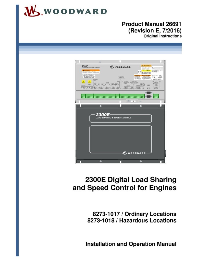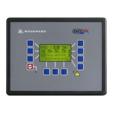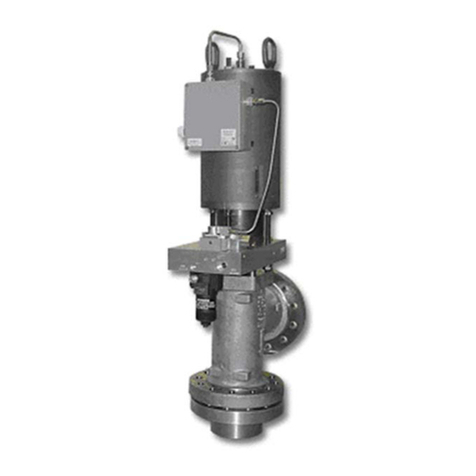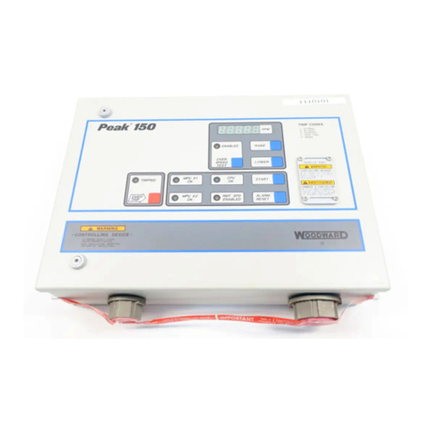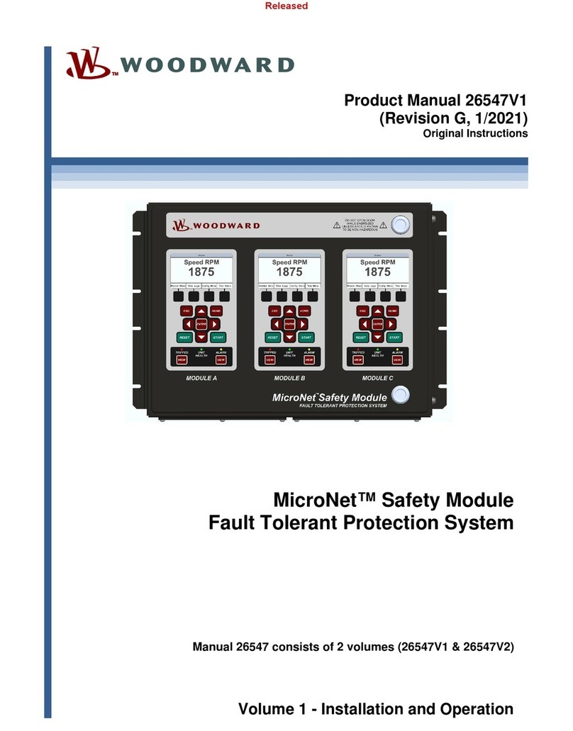
Manual 02035 Load Sharing Module
Woodward i
Contents
ELECTROSTATIC DISCHARGE AWARENESS .................................................. II
CHAPTER 1. GENERAL INFORMATION...........................................................1
Introduction.............................................................................................................1
Description..............................................................................................................1
CHAPTER 2. INSTALLATION..........................................................................6
Introduction.............................................................................................................6
Unpacking...............................................................................................................6
Location Considerations .........................................................................................6
General Wiring Requirements ................................................................................7
Power Requirements ..............................................................................................7
Shielded Wiring ......................................................................................................7
Generator Connections ..........................................................................................9
Current Transformers .............................................................................................9
Load Sharing Lines, Droop, and Auxiliary Contacts...............................................9
Output to the Engine Speed Control ....................................................................10
Synchronization Connections...............................................................................10
Speed Trim Potentiometer....................................................................................10
External 5 Vdc Reference (Optional)....................................................................10
CHAPTER 3. SETUP AND CALIBRATION ......................................................11
Introduction...........................................................................................................11
Phasing Check .....................................................................................................12
Phase Correction Procedure ................................................................................13
Load Gain Adjustment ..........................................................................................16
Droop Adjustment.................................................................................................17
Setting Droop for an Isolated Load.......................................................................17
Setting Droop for an Infinite Bus ..........................................................................18
CHAPTER 4. THEORY OF OPERATION.........................................................19
Introduction...........................................................................................................19
Power Supply .......................................................................................................19
Power Sensor .......................................................................................................19
Load Comparator Circuit ......................................................................................19
Speed Trim Circuit................................................................................................19
Isochronous Load Sharing....................................................................................20
Droop Operation ...................................................................................................20
Auxiliary Equipment..............................................................................................20
0.5–4.5 Vdc Output...............................................................................................20
CHAPTER 5. TROUBLESHOOTING...............................................................21
CHAPTER 6. SERVICE OPTIONS .................................................................23
Product Service Options.......................................................................................23
Woodward Factory Servicing Options ..................................................................24
Returning Equipment for Repair...........................................................................25
Replacement Parts ...............................................................................................25
Engineering Services............................................................................................26
How to Contact Woodward...................................................................................26
Technical Assistance............................................................................................27
APPENDIX.LSM CONTROL SPECIFICATIONS..............................................28
DECLARATIONS.........................................................................................31
