manuals.online logo
Brands
  1. Home
  2. •
  3. Brands
  4. •
  5. IBC
  6. •
  7. Control Unit
  8. •
  9. IBC P-272 User manual

IBC P-272 User manual

120-307-R1 (1/25/2019)www.ibcboiler.com │1
P-272 Safety and Ignition Module (SIM) conversion kit
IBC Part # Description Boiler Model
P-272 SIM conversion kit VFC modulating Series (VFC 15-150, VFC 45-225)
Warning
For your safety, turn off the electrical power supply at the service panel, and allow the unit to cool before
proceeding. The ability to perform service on this equipment requires certain expertise, mechanical skills, tools,
and equipment. If you do not possess these, do not attempt to perform any service on this equipment. Failure to
follow this warning could result in possible in damage to this equipment, serious personal injury, or death.
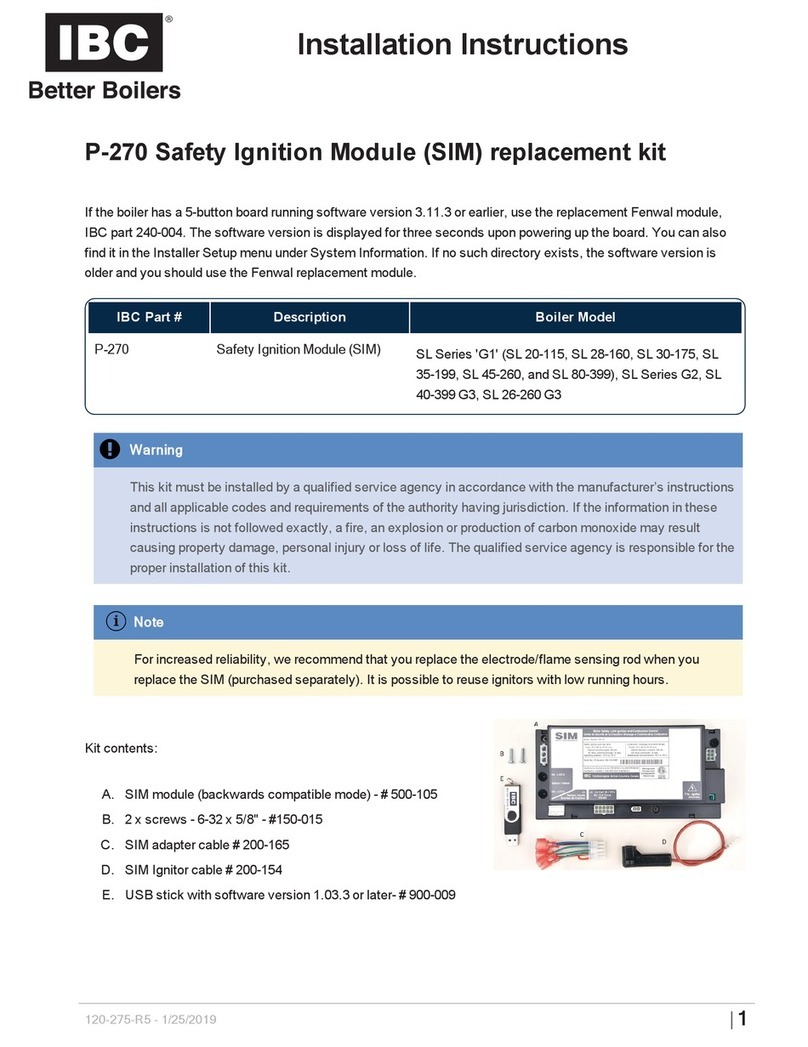
Kit contents:
A. 1 x Safety and Ignition Module (SIM) - IBC Part # 500-105
B. 1 x SIM - VFC retrofit plate with air sensor bracket – IBC Part 250-
876
C. 2 x Screws, Pan Head, Philips, 6-32 x 3/8" - IBC Part # 150-014
D. 2 x Screws, Pan Head, Philips, 6-32 x 5/8" - IBC Part # 150-015
E. 1 x Fenwal to SIM Ignition Module Adapter Cable - IBC Part # 200-
165
F. 1 x VFC SIM Ignition Cable - IBC Part # 200-166
G. 1 x VFC, SIM Ground Wire Adapter – IBC Part #200-167
When to install the P-272 SIM ignition module conversion kit
If the boiler has a 5-button board running software version 3.11.3 or earlier, use the replacement Fenwal module, IBC part
240-004. The software version is displayed for three seconds upon powering up the board. You can also find it in the
Installer Setup menu under System Information. If no such directory exists, the software version is older and you should
use the Fenwal replacement module.
Installation Instructions
Use the P-272 SIM Ignition module conversion kit to
replace a Fenwal ignition module for any boiler using a
touchscreen controller or a 5-button controller with
software version 3.11.4.
Note
the Fenwal module is not necessarily defective
when the boiler reports an Ignition Module error.
A mechanical error such as Low Water Cut-Off
may also cause Ignition Module alarms.
The earlier VFCs models were fixed-fire boilers that used
a controller with an integrated ignition module. Contact
the factory for fixed-fire VFC boiler replacement parts.
Pre-installation guidelines
For increased reliability, we recommend that you replace
the electrode/flame sensing rod when you replace the
SIM (purchased separately). It is possible to reuse
ignitors with low running hours.
Installing a P-272 Ignition
module kit
Figure 1 Wiring connections to the SIM module
1. Remove any call for heat, and power off the boiler.
2. Remove the front door panel from the cabinet, and
allow the boiler to cool.
2│www.ibcboiler.com
3. Only drain the boiler should the boiler’s water
be susceptible to freezing while the boiler is off.
4. Turn off the gas supply.
5. To remove the puck-shaped air pressure
sensor from its metal mounting bracket, lift it
straight upwards.
Figure 2 Lifting off the air pressure sensor
6. Unscrew the air pressure sensor mounting
bracket from the controller cabinet.
The Fenwal ignition module is mounted on the
back wall of the VFC, partly hidden by the
black intake air piping. You do not need to take
apart this piping nor remove the Fenwal.
7. Unplug the orange, blue, brown, and green
wires from the module. You can leave the
Fenwal module in place.
8. On top of the heat exchanger:
a. Unplug the ignitor cable boot from the
ignitor.
b. Connect the new 200-166 ignitor cable
firmly to the ignitor, then feed the cable
through the back of the heat exchanger,
passing over the top of the heat
exchanger mounting bracket (see Figure 3
). Remove the old ignition cable if
practical, or use as a fixing point for the new
cable.
c. Plug the new ignitor cable into the SIM
module T1b terminal.
Figure 3 Feeding the new ignitor cable
behind the heat exchanger
9. Insert the supplied ground wire adapter (part
#200-167) into the green harness wire (removed
from the Fenwal in step 7).
10. Plug the other end of the ground wire adapter into
any of the green connectors on the supplied cable
adapter # 200-165.
11. Plug the orange, blue, and brown harness wires
(removed from the Fenwal in step 7) onto the
corresponding colored wires of the supplied cable
adapter # 200-165.
12. Insert the cable adapter plug into the SIM, into the
J2 socket labeled “24 VAC IN...”
13. Mount the replacement SIM behind the controller
by aligning the two holes in the SIM mounting
bracket with the holes vacated by the air pressure
sensor bracket. (See Figure 4 ). Reuse the
original screws or the supplied 6-32 x 3/8" screws
to fix SIM bracket to boiler. A Philips screwdriver
4" or shorter will engage the rear screw without
interference from combustion air piping.
120-307-R1(1/25/2019)www.ibcboiler.com |3
Figure 4 Positioning the connected P-272
14. Reinstall the air pressure sensor onto the top of
the SIM bracket. The fit may be looser than on
the original bracket.
15. Check the installation for wire routing and loose
ends.
16. Open the gas supply, and repower the boiler.
17. Re-establish a call for heat, and confirm proper
operation.
Note about Flame Signal
After installation, confirm a smooth and reliable
ignition and also that the flame current is strong
throughout the entire input range. Ensure that
you use a multimeter to measure the flame
current and leads with Category 3 protection or
better (the flame sensor circuit also carries the
high-voltage ignition spark). The multimeter
must be capable of measuring between 1-10
microamps DC with a resolution of 0.1 μA.
The SIM expects a flame current of at least 0.8
µA. At low-fire, an ignitor may register a poor
flame current if it is placed too far from the
burner. Improper combustion can also be a
factor.
For gapping the P-111 double-prong ignitor,
used on removable-lid VFCs heat exchangers,
observe the gap through the sight glass. If the
glass is too cloudy, remove the sight glass
assembly, clean and then replace.
Adjust the ignitor by using two pliers to bring the
ends of both prongs of the ignitor about 3/8"
(10mm) from the burner surface. As the ignitor
diameter is about 1/8", this is about 3 rod
diameters. Used ignitors should be heated up
(e.g., in a torch) for adjustment. Care should be
taken to prevent stress to the ceramic
insulation.
For gapping the P-142 single-prong ignitor, see
the Installation Instructions that come with the
ignitor, also available on the Technical
Information Portal at ibcboiler.com.
4│www.ibcboiler.com

Other IBC Control Unit manuals

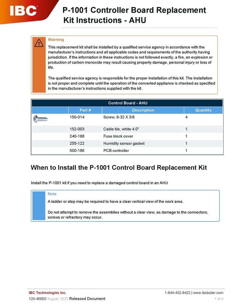
IBC P-1001 User manual

IBC

IBC P-1001 User manual

IBC P-270 User manual

IBC

IBC P-270 User manual

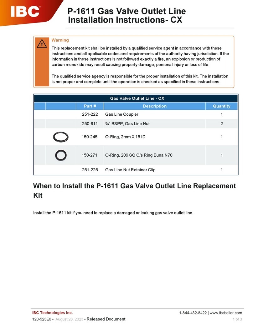
IBC P-1610 User manual

IBC

IBC P-1610 User manual

Popular Control Unit manuals by other brands

Tyco DV-5A Summary Instructions

Tyco

Tyco DV-5A Summary Instructions

Bola E 683-18 operating instructions

Bola

Bola E 683-18 operating instructions

Woodward 9907-252 Installation and operation manual

Woodward

Woodward 9907-252 Installation and operation manual

M-system R3-AS4 instruction manual

M-system

M-system R3-AS4 instruction manual

Kramer VM-8UX user manual

Kramer

Kramer VM-8UX user manual

National Instruments 5772R User manual and specifications

National Instruments

National Instruments 5772R User manual and specifications

Honeywell 804973 Installation instruction

Honeywell

Honeywell 804973 Installation instruction

Sierra Wireless AirPrime SL808 Series Migration guide

Sierra Wireless

Sierra Wireless AirPrime SL808 Series Migration guide

O&O LOG-BC Installation and operation manual

O&O

O&O LOG-BC Installation and operation manual

ITT Flygt 4901 Installation, Care and Maintenance

ITT

ITT Flygt 4901 Installation, Care and Maintenance

AVK 41 Series Installation, operation and maintenance manual

AVK

AVK 41 Series Installation, operation and maintenance manual

ADTRAN Job Aid+ 1442707G3 manual

ADTRAN

ADTRAN Job Aid+ 1442707G3 manual

IONODES ATOMAS-MINI-DUAL user manual

IONODES

IONODES ATOMAS-MINI-DUAL user manual

TESTO 0560 5600 quick start guide

TESTO

TESTO 0560 5600 quick start guide

Silicon Laboratories MGM13S Series manual

Silicon Laboratories

Silicon Laboratories MGM13S Series manual

Ebyte E103-W03 Product instruction manual

Ebyte

Ebyte E103-W03 Product instruction manual

Audiophonics Up2Stream WA31 user manual

Audiophonics

Audiophonics Up2Stream WA31 user manual

Stem NC97 operating instructions

Stem

Stem NC97 operating instructions

manuals.online logo
manuals.online logoBrands
  • About & Mission
  • Contact us
  • Privacy Policy
  • Terms and Conditions

Copyright 2025 Manuals.Online. All Rights Reserved.