AVK 41 Series User manual

Page 1 of 18 Copyright © AVK Holding A/S, original version, rev. 1, 21-Jan-2023
Installation, Operation and Maintenance Manual -
Original Version
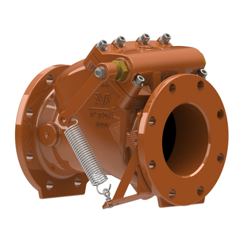
AVK Series 41, Swing Check Valves, DN 50-300
The AVK series 41 swing check valves are installed in water supply and wastewater
lines to make water flow in only one direction.
Flow reversal can occur for different reasons, like e.g. pump stop in a plant with large
differences in altitude, but with a check valve in the line this can be effectively
controlled.
Valves in the size range DN 50-300 come as both resilient and metal seated with the
resilient seated having a rubber face pressing against the cast iron seat and the metal
seats consisting of copper alloy face- and seat rings.

Page 2 of 18 Copyright © AVK Holding A/S, original version, rev. 1, 21-Jan-2023
1. AVK series 41, swing check valves, exploded view

Page 3 of 18 Copyright © AVK Holding A/S, original version, rev. 1, 21-Jan-2023
2. AVK series 41, parts list
No.
Item
Material
No
Item
Material
1
Valve Body
Ductile iron
21
Set Screw
Stainless Steel
2
Disc Nut
Stainless steel
22
Rubber Encapsulation
EPDM
3
Disc Washer
Stainless steel
23
Closed Bushing
Copper alloy
4
Disc Bushing
Polyamide
24
Disc Lock Washer
304 Stainless steel
5
Hinge
Stainless steel/ductile iron/bronze
25
Spring
Stainless Steel
6
Washer
Stainless steel
26
Spring Eyebolt
Stainless Steel
7
Bonnet Bolt
Stainless steel
27
Spring Eyebolt Nut
Stainless Steel
8
Bonnet
Ductile iron
28
Spring Eyebolt Washer
Stainless Steel
9
Shaft
Stainless steel
29
Spring Bracket
Carbon Steel
10
Key
Stainless steel
30
O-ring
EPDM
11
Lock Washer
Stainless steel
31
Hinge Connector
Stainless Steel
12
Hinge Bolt
Stainless steel
32
Retaining Washers
Stainless Steel
13
Bonnet Gasket
EPDM
33
Shaft Spacers
Stainless Steel
DN50: Gunmetal
34
Spring Arm Washer
Stainless Steel
14
Disc
DN65-200: Stainless steel
35
Spring Arm Nut
Stainless Steel
DN250-300: Ductile iron
36
Spring Arm rod
Stainless Steel
15
Shaft Nut
Stainless steel
37
Spring Bracket Bolt
Stainless Steel
16
Shaft Washer
Stainless steel
38
Spring Arm Spacer
Stainless Steel
17
Lever
Ductile iron
39
Shaft Lock Washer
Stainless Steel
18
Open Bushing
Copper alloy
40
Spring Bracket Mount Washer
Stainless Steel
19
Inner Bushing O-rings
EPDM
41
Seat Ring, Disc Part
Bronze
20
Weight
Cast iron
42
Seat Ring, Body Part
Bronze
Item 31-40 refer to Fig. 10, DN250-300 only

Page 4 of 18 Copyright © AVK Holding A/S, original version, rev. 1, 21-Jan-2023
3. Table of contents
1. AVK series 41, swing check valves, exploded view...........................................................2
2. AVK series 41, parts list ....................................................................................................3
3. Table of contents...............................................................................................................4
4. Principle of operation.........................................................................................................5
5. Health and safety at work..................................................................................................6
6. Receiving and storage.......................................................................................................7
7. Installation and commissioning..........................................................................................8
7.1 Flow direction.............................................................................................................9
7.2 Lever and weight / spring (optional)............................................................................9
7.3 Adjusting lever and weight........................................................................................10
7.4 Installation of lever and weight .................................................................................12
7.5 Lever and spring, DN200 and below (optional).........................................................13
7.6 Lever and spring, DN250-300 (optional)...................................................................14
8. Application hazards.........................................................................................................15
9. Operation and maintenance............................................................................................15
9.1 Operation .................................................................................................................15
9.2 Maintenance.............................................................................................................15
9.3 Disassembly for inspection and cleaning..................................................................16
9.4 Renewal of shaft and bushings.................................................................................16
10. Decommissioning............................................................................................................17
11. Trouble shooting .............................................................................................................17
12. Recommended spare parts.............................................................................................18
13. Head Loss.......................................................................................................................18
Page 5 of 18 Copyright © AVK Holding A/S, original version, rev. 1, 21-Jan-2023
4. Principle of operation
The main operating principle is simple and reliable: a hinged disc in the water stream swings
open when the flow is forward and shuts off against the valve seat if the flow tends to reverse.
If the reverse water flow shall deliver the force to close the disc there is risk of water hammer
and to mitigate this a weighted or spring-loaded lever can be attached to the hinge shaft. This
helps force the valve closed before the flow reverses and thus results in quiet operation.
The drawback is higher pressure loss when the water is flowing, but correct adjustment of
spring tension and weight position can minimise this.
Adding a weight or a spring also makes it possible to operate in vertical installations with
downwards flow.
The valve seat is either metal or resilient rubber. The disc is mounted in a flexible rubber
bushing allowing it to tilt slightly in all directions and adjust exactly to the valve seat.
Fig. 1, Rubber seat Fig. 2, Metal seat
No
Item
Material
1
Valve Body
Dutile Iron
14
Disc
Gunmetal / Stainless Steel / DI
22
Rubber Encapsulation
EPDM
41
Seat Ring, Disc Part
Copper alloy
42
Seat Ring, Body Part
Copper alloy

Page 6 of 18 Copyright © AVK Holding A/S, original version, rev. 1, 21-Jan-2023
5. Health and safety at work
Make sure all relevant Health and Safety issues and regulations are adhered to prior to and
during installation or maintenance work carried out on this product. It is the end user's
responsibility to ensure that safe working practices are followed at all times.
Whenever AVK’s products are installed, operated or maintained the inherent dangers of
pressurised liquids and gasses must be addressed. Before work on a valve or other piping
component is undertaken, that may involve the release of internal pressure, the valve or line
must be fully isolated, depressurised and drained prior to commencing the work. FAILURE TO
COMPLY WITH THIS MAY RESULT IN SEVERE INJURY OR DEATH.
All workers handling the product must be aware of the weight of the components or assemblies
to be handled and manipulated during installation and maintenance.
It is essential that staff undertaking these operations are adequately trained and it is the
responsibility of the end user that only trained and competent staff undertake these duties.
This manual has been designed to assist, but it cannot replace quality training in the workplace.
However, the AVK technical staff is always available and ready to answer questions relating to
specific problems that may not be covered by this manual.
AVK’s products are designed to be fit for purpose and to a high reliability standard. This
provides a safe, low risk product when used correctly for the purpose for which it was designed.
However, this assumes that the equipment is used and maintained in accordance with this
manual, and the user is advised to study it and to make it available to all staff that may need to
refer to it.
AVK cannot be held responsible for incidents arising from incorrect installation, operation or
maintenance. The responsibility for this rests wholly with the end user.

Page 7 of 18 Copyright © AVK Holding A/S, original version, rev. 1, 21-Jan-2023
6. Receiving and storage
Unloading must be carried out carefully. The load must be put gently to the ground without
dropping.
Do not lift in the shaft or weight/lever, lift only by means of shackles in the flange bolt holes or
slings around the body casting.
If a forklift is used it shall have sufficient capacity to lift the required weight and have a valid
inspection certificate.
All workers involved in the unloading shall be able to perform their functions. They shall wear
safety boots, safety vest, safety goggles and hard hat.
All slings used for the lifting shall be of sufficient strength. A record shall document that they
have been stored under cool, dry conditions away from sunlight and chemical atmosphere, and
that they still perform according to their marked strength.
Immediately after unloading the item should be inspected for compliance with specifications and
damage in shipment.
Compliance with specification check will typically comprise size, pressure class, flange drilling,
face-to-face, accessories (lever, weight, springs, guards, remote sensors, etc.)
Damage in shipment check shall comprise coating, protruding shaft ends, accessories and all
other parts that could have been exposed to mishandling during shipment.
Check that the disc and shaft move freely from one end position to the other and make sure to
check it in the position in which the valve is to be installed.
Storage shall be under dry, cool conditions, away from direct sunlight and corrosive or
otherwise chemically active atmosphere.

Page 8 of 18 Copyright © AVK Holding A/S, original version, rev. 1, 21-Jan-2023
7. Installation and commissioning
WARNING: Prior to installation make sure that all pressurized lines involved in the installation
are isolated, depressurized and drained before starting any work. Failure to do so may result in
sudden pressure release and subsequent severe injury or death.
The valve must be installed in a way that gives access to maintenance or inspection. Ample
room around the shaft cover should be left to allow for hoisting equipment for taking out the disc
and shaft.
The valve and adjacent piping must be supported and aligned to prevent cantilevered stress on
the valve.
Shaft and hinge must always be horizontal and never below the disc.
Keep a distance of at least 5-6 pipe diameters to the nearest upstream elbow, tee, control valve
or other kind of equipment that can cause turbulence in the water stream.
The valve must be provided with adequate support and the adjoining pipework must not transfer
stress to the valve body.
Flange bolts should be tightened gradually in a criss-cross sequence as shown on fig. 3.
Fig. 3, Example of a tightening sequence, 12-bolts flange
Finally torque the bolts to the value specified by the gasket manufacturer. If this is not available,
the values stated in table 1 can be used as a guideline for the maximum torque.
Valve size
Bolt size
Torque
PN10 / PN16
Nm
DN 80
M16 / M16
100
DN 100
M16 / M16
100
DN 150
M20 / M20
110
DN 200
M20 / M20
110
DN 250
M20 / M24
150
DN 300
M20 / M24
150
Table 1, Flange bolts torque values

Page 9 of 18 Copyright © AVK Holding A/S, original version, rev. 1, 21-Jan-2023
7.1 Flow direction
There are three main configurations
1. When installed with horizontal flow the hinge and shaft must also be horizontal and
above the disc. Add a lever with spring or weight if necessary. Horizontal flow is the
recommended configuration.
2. When installed with vertical rising flow the disc itself will act as a weight that helps close,
but a lever with weight or spring might still be necessary depending on the installation.
3. When installed with vertical downwards flow a lever with spring or weight must always
be fitted to make sure the valve can close.
Fig. 4, Recommended configuration
7.2 Lever and weight / spring (optional)
In some applications a pump stop can cause a sudden reverse flow that makes the check valve
close violently causing water hammer. This phenomenon is the source of large pressure spikes
in the pipe system and can potentially damage components and cause leaks. To mitigate this a
lever can be attached to the hinge shaft and with a weight or a spring it can be adjusted to close
the valve quickly and quietly by actively stopping the flow before it can reverse.
A side effect is an increased pressure drop across the valve depending how strongly the closing
torque is applied, i.e. mass and position of the weight or strength of the spring. To reduce un-
necessary energy consumption make sure a good balance is found where the risk of water
hammer is effectively reduced at the lowest possible head loss.
The lever with weight or spring must be adjusted according to the application. If the flow is low
the least aggressive position will most often be used, i.e. the one that requires low pressure to
open initially, but high pressure to keep wide open.

Page 10 of 18 Copyright © AVK Holding A/S, original version, rev. 1, 21-Jan-2023
7.3 Adjusting lever and weight
Warning: Do not adjust the weight and lever while the system is operational. The lever can
suddenly move with great force and cause injury
The hexagon end of the shaft allows for 6 different positions of the lever, 60° apart. Select the
one that best fits the requirements of the installation.
The lever swings approx. 70-75° from fully closed to fully open, so in the fully open state the
lever will be 10-15° further anticlockwise than the next possible closed position shown on fig. 5.
For horizontal flow use 1 or 2
For vertical rising flow use 6 or 1
For vertical downwards flow use 3 (or 4)
Fig 5, Weight positions when closed, 1 to 6
Each of the three main configurations has only two possible positions of the lever/weight:
•The lever close to vertical when closed and close to horizontal when fully open. This
characteristic resembles that of a spring with the closing force becoming gradually
stronger the more the valve opens. Reaction time is long at low flow and short at high
flow.
•A more aggressive position has the lever close to horizontal when closed and close to
upwards vertical when fully open. It reacts quickly at low flow, slowly at full flow and
requires more pressure to open.
On some variants the lever in fully open position can pass the vertical point and drop
down on the other side leaving the valve inoperable. In that case the aggressive position
cannot be used.

Page 11 of 18 Copyright © AVK Holding A/S, original version, rev. 1, 21-Jan-2023
Figure 6 shows two different scenarios with position 1:
•In the horizontal configuration it is the standard position with low opening pressure.
Turning the lever anticlockwise 60° to pos. 2 selects the more aggressive characteristic.
•With vertical rising flow it is the other way around; position 1 requires high forward
pressure to open, is quick to close at low flow and has lower head loss at full flow. To get
the less aggressive action turn the lever clockwise 60° to pos. 6.
Fig. 6, Lever/weight configurations, pos. 1
Vertical installation with downwards flow is possible, but since the default position of the valve in
this configuration is fully open, the use of a lever and weight is essential.
Position 3 as shown in fig. 7, is recommended as the safe choice.
The aggressive position 4 is very close to vertical at fully open. Make sure it does not pass this
point and drop down on the other side leaving the valve inoperable. Position 4 must in any case
be expected to react very slowly from maximum flow.
Fig. 7, Downwards flow, pos. 3

Page 12 of 18 Copyright © AVK Holding A/S, original version, rev. 1, 21-Jan-2023
7.4 Installation of lever and weight
Secure the lever (17) with the shaft washer (16) and shaft nut (15) and tighten to 40Nm. Attach
the weight (20) and tighten the set screw (21) to hold the weight in place.
A medium strength thread locking compound should be used to secure the installation.
To adjust closing speeds for optimum performance the weight can be moved on the lever in
order to change the torque applied to the shaft, hinge and disc.
Fig. 8, Weight Components

Page 13 of 18 Copyright © AVK Holding A/S, original version, rev. 1, 21-Jan-2023
7.5 Lever and spring, DN200 and below (optional)
Instead of a weight a spring can be fitted to assist in closing the valve. It has the advantage of
taking up less space and having less inertia, but adjustments are limited.
A spring bracket (29) is attached to the flange bolts.
Install the spring eyebolt (26) on the spring bracket, securing it with the nuts (27), and washers
(28), one washer and nut on each side of the spring bracket (29).
Slide the lever (17) onto the shaft (9) and position as shown in figure 8.
Secure the lever with the shaft washer (16) and shaft nut (15) and tighten to 40Nm.
Attach the spring (25).
Fig. 9, Spring adjustment, DN≤200

Page 14 of 18 Copyright © AVK Holding A/S, original version, rev. 1, 21-Jan-2023
7.6 Lever and spring, DN250-300 (optional)
The large DN250 and DN300 valves will have the lever and spring assembly installed at the
factory.
Fig. 10, Lever and spring on DN>200
No
Item
Material
No
Item
Material
8
Bonnet
Ductile iron
27
Spring Eyebolt Nut
Stainless Steel
9
Shaft
Stainless steel
28
Spring Eyebolt Washer
Stainless Steel
10
Key
Stainless steel
29
Spring Bracket
Carbon Steel
13
Bonnet Gasket
EPDM
30
O-ring
EPDM
14
Disc
Ductile iron
31
Hinge Connector
Stainless Steel
15
Shaft Nut
Stainless steel
32
Retaining Washers
Stainless Steel
16
Shaft Washer
Stainless steel
33
Shaft Spacers
Stainless Steel
17
Lever
Ductile iron
34
Spring Arm Washer
Stainless Steel
18
Open Bushing
Copper alloy
35
Spring Arm Nut
Stainless Steel
19
Inner Bushing O-rings
EPDM
36
Spring Arm rod
Stainless Steel
23
Closed Bushing
Copper alloy
37
Spring Bracket Bolt
Stainless Steel
24
Disc Lock Washer
304 Stainless steel
38
Spring Arm Spacer
Stainless Steel
25
Spring
Stainless Steel
39
Shaft Lock Washer
Stainless Steel
26
Spring Eyebolt
Stainless Steel
40
Spring Bracket Mount Washer
Stainless Steel

Page 15 of 18 Copyright © AVK Holding A/S, original version, rev. 1, 21-Jan-2023
8. Application hazards
•If the installation is prone to sudden pump stop and flow reversal a lever with weight
must be fitted to the shaft to help close the valve quickly
•If fitted with lever and weight check the pressure drop when operating - a balance should
be found where the risk of water hammer is sufficiently reduced while still having the
lowest possible pressure drop across the valve
•Maximum operating temperature is 70°C (WRAS approval valid to max. 50°C) and
maximum flow speed is 4m/s
•Do not install where ambient temperature drops below freezing for the medium unless
sufficient insulation or other frost protection is provided
•Keep a distance of at least 5-6 pipe diameters downstream of components creating
turbulence, like control valves, elbows, tees, etc.
•Do not install in sewage lines with large pieces of debris that can jam the disc movement
•Installation with vertical downwards flow is possible, but works only with lever and weight
or spring to close the valve
•When installing lever/weight make sure to put it in a position that will always turn the
shaft towards closing regardless of flow condition, i.e., that it does not pass vertical when
moving against fully open
•The metal seated versions cannot be expected to close drop tight and should not be
used in applications where this is required
•Do not use with solvents or flammable liquids
9. Operation and maintenance
9.1 Operation
The valve operates automatically.
9.2 Maintenance
WARNING: Prior to any maintenance work that requires disassembly make sure that the
pressurized line involved is isolated, depressurized and drained before starting any
disassembly. Failure to do so may result in sudden pressure release and subsequent severe
injury or death.
Very little maintenance is required, but the following parts should be inspected periodically:
- Hinge and disc should be kept clear of debris
- If the valve does not operate frequently and is kept in either open or closed position for
long periods of time, it should be exercised regularly depending on the water quality and
amount of minerals and debris that could deposit.
- Check shaft and bushings for excessive wear –particularly relevant in installations with
fluctuating or low flow
- Clean the sump in the bottom of the valve body
- Clean the surface and check for damage
- Check all seals for leakage
- Check by-pass and priming device for leakage, if installed
If the shaft seals leak in the bushings, check that they are properly tightened. If the leak
persists, replace the O-rings.

Page 16 of 18 Copyright © AVK Holding A/S, original version, rev. 1, 21-Jan-2023
9.3 Disassembly for inspection and cleaning
The valve body does not need to be removed from the pipeline to remove the bonnet and the
inner parts.
1) Depressurize the pipeline completely; not only for safety reasons but also because when
loosening the bonnet bolts even a slight overpressure can shoot out the bonnet gasket
and damage it
2) Remove lever and spring or weight if installed
3) Note bolt length when he bolts are removed. The bonnet bolts are different lengths with
the longer located upstream.
4) Inspect head assembly for worn or damaged parts. If resilient seated, inspect the disc for
tears or cracks in the rubber.
9.4 Renewal of shaft and bushings
O-rings (19, 30), bushings (4, 18, 23) and shaft (9) are likely to be worn over time if the valve is
operating constantly. Replace as necessary.
Fig. 11, Shaft and bushings

Page 17 of 18 Copyright © AVK Holding A/S, original version, rev. 1, 21-Jan-2023
10. Decommissioning
When decommissioning the valve it should be disposed of according to local regulations and in
a way that allows as much recycling of materials as possible.
AVK series 41 check valves do not contain hazardous materials that require special treatment.
11. Trouble shooting
Symptom:
Leakage at the shaft bushings
Cause:
Loose bushing
Cure:
Torque to 60Nm
Symptom:
Leakage at the shaft bushings
Cause:
Worn O-rings
Cure:
Replace O-rings
Symptom:
Leakage at the bonnet
Cause:
Loose bonnet bolts
Cure:
Torque to 60Nm
Symptom:
Leakage at the bonnet
Cause:
Damaged gasket, this can happen if the valve is not completely de-pressurised
before loosening the bonnet bolts
Cure:
Replace gasket
Symptom:
Valve leaks slightly when closed, metal seated
Cause:
Design
Cure:
No cure for this; metal seats are not drop tight
Symptom:
Valve leaks when closed
Cause:
Dirty, worn out or damaged seal
Cure:
Clean or replace disc
Symptom:
Valve does not open
Cause:
Low forward pressure
Cure:
Adjust spring or weight
Symptom:
Valve stays open and does not operate
Cause:
Lever mounted on shaft in a wrong angle
Cure:
Check section 7.3 for correct lever angle.
When installed with downwards vertical flow in position 4 a high flow situation
can cause the weight to tip over vertical to a position where the valve is
permanently open.

Page 18 of 18 Copyright © AVK Holding A/S, original version, rev. 1, 21-Jan-2023
12. Recommended spare parts
Only genuine AVK spare parts should be used.
AVK cannot accept responsibility for damage caused by failing non-AVK parts.
Following spare parts are recommended to purchase with a ser. 41 valve:
1. O-rings for shaft
2. Bonnet gasket
3. Shaft bushings
4. Complete disc
13. Head Loss
Head loss with cold water in horizontal flow in basic configuration with neither weight nor spring
attached is shown below on fig. 12.
With spring or weight installed the pressure loss will be greater and it will vary depending on
how lever position, weight position or spring tension are adjusted.
Fig. 12, Head Loss
1
10
110 100 1000
mBar
m³/h
Head Loss Calculation, AVK ser. 41, DN50-300
DN50
DN65
DN80
DN100
DN125
DN150
DN200
DN250
DN300
Other manuals for 41 Series
4
This manual suits for next models
1
Table of contents
Other AVK Control Unit manuals

AVK
AVK 854 series User manual

AVK
AVK 715 Series User manual

AVK
AVK 41 Series User manual

AVK
AVK 879 Series Instruction manual

AVK
AVK 41 Series Instruction manual

AVK
AVK 756 Series Instruction Manual

AVK
AVK 820 SERIES Installation and operating instructions

AVK
AVK ACMO 879 Series Instruction manual

AVK
AVK 41 Series User manual

AVK
AVK 54 Series Instruction manual