IBC P-1627 Guide

P-1627 Heat Exchanger Lid
IBC Technologies Inc. 1-844-432-8422 |www.ibcboiler.com
120-538E0 -October 20, 2023 - Released Document 1 of 6
Replacement Instructions- CX 150
Warning
This replacement kit shall be installed by a qualified service agent in accordance with these
instructions and all applicable codes and requirements of the authority having jurisdiction. If the
information in these instructions is not followed exactly a fire, an explosion or production of
carbon monoxide may result causing property damage, personal injury or loss of life.
The qualified service agency is responsible for the proper installation of this kit. The installation
is not proper and complete until the operation is checked as specified in these instructions.
Warning
The IBC heat exchanger has a small amount of combustion chamber insulation (refractory), which
contains ceramic fibers.
When exposed to extremely high temperatures, the ceramic fibers that contain crystalline silica
can be converted into cristobalite, classified as a possible human carcinogen.
Avoid disturbing or damaging the refractory. If damage occurs, contact the factory for directions.
Avoid breathing and contact with skin and eyes and follow these precautions:
1. For conditions of frequent use or heavy exposure, respirator protection is required. Refer to
the “NIOSH Guide to the Selection and Use of Particulate Respirators Certified under 42
CFR 84” for selection and use of respirators certified by NIOSH.
For the most current information, NIOSH can be contacted at 1-800-356-4676 or on the web
at www.cdc.gov/niosh.
2. Wear long sleeved, loose fitting clothing, gloves and eyes protection.
3. Assure adequate ventilation.
4. Wash with soap and water after contact.
5. Wash potentially contaminated clothes separately from other laundry and rinse washing
machine thoroughly.
6. Discard used insulation in an air tight plastic bag.
NIOSH stated first aid:
Eye contact - Irrigate and wash immediately.
Breathing - Provide fresh air.

IBC Technologies Inc. 1-844-432-8422 |www.ibcboiler.com
120-538E0 -October 20, 2023 - Released Document 2 of 6
Note
This kit does not come with a replacement burner.
Please clean and reuse the original burner as directed in Exchanging the Burner on page 4.
If the burner needs to be replaced, order P-1519.
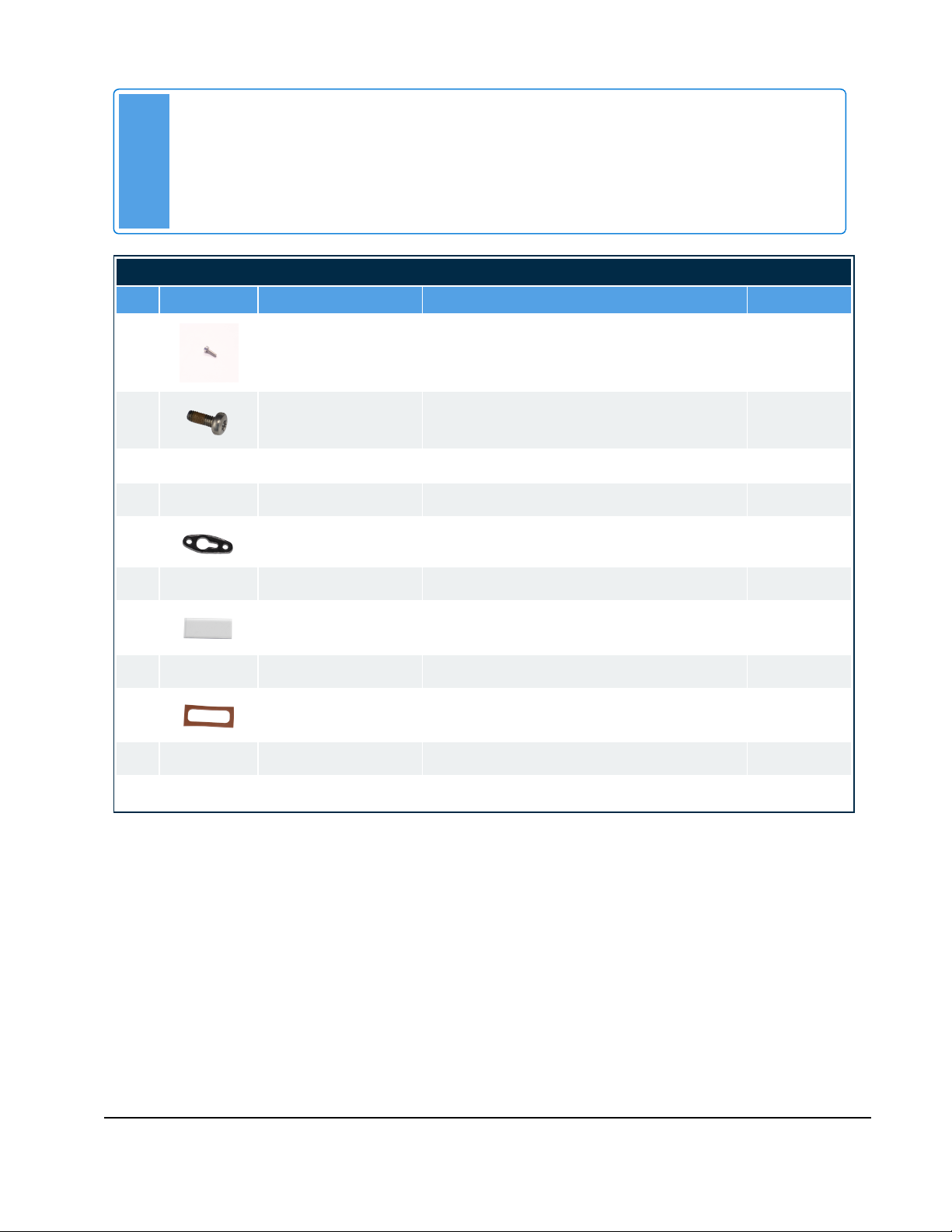
Heat Exchanger Lid -CX 150
Part # Description Quantity
150-012 Screw, SHC, S/S, M3x10 2
150-260 Screw, 6 T/ Pan S/S, M4-0.7x10mm 8
170-126 Lid, Burner, VC45 1
240-182 Ignitor, VC (Kanthal APM 3.0) 1
250-050 Gasket, Ignitor 1
250-057 Housing, Viewport 1
250-059 Glass Insert, Viewport 1
255-023 Gasket- Sight Glass To Lid, SL 1
255-025 Gasket- Viewport Upper 1
255-141 Gasket, Burner VC45&60 1
255-152 Refractory, VC150 1
When to Install the P-1627 Heat Exchanger Lid Replacement
Kit
Install the P-1627 kit if you need to replace a heat exchanger lid that has been damaged.

IBC Technologies Inc. 1-844-432-8422 |www.ibcboiler.com
120-538E0 -October 20, 2023 - Released Document 3 of 6
Note
A ladder or step may be required to have a clear vertical view of the work area.
Do not attempt to remove the assemblies without a clear view, as damage to the connectors,
screws or refractory may occur.
CX 150 Heat Exchanger Lid Replacement
Preparing the Unit for Servicing
1. Remove call(s) for heat.
2. Remove power to the unit at a wall switch or a breaker.
3. Shut off gas supply to the boiler.
4. Allow the boiler to cool down.
5. Remove the front cover, and then remove the four Torx 20 head screws on the top panel of the combi
boiler.
Accessing the Service Area
A. Removing the Gas Line and Gas Valve:
a. Unplug the electrical connection to the gas valve.
b. Undo the union nut (A) at the gas inlet(B).
c. Undo the union nut (C) connecting the gas valve
outlet pipe to the mixer (D).
d. Carefully remove the gas line and valve assembly
and set aside for re-installation.
Figure 1 CXGas Line Assembly Removal
B. Removing the Fan/ Mixer assembly:
a. Remove the electrical connection to the fan.
b. Unscrew the two nuts at the base of the fan, and retain for re-installation.
c. Carefully lift and tilt the fan/ mixer assembly backwards to safely remove it from the heat
exchanger lid.
d. Remove and retain the fan gasket.

IBC Technologies Inc. 1-844-432-8422 |www.ibcboiler.com
120-538E0 -October 20, 2023 - Released Document 4 of 6
Removing the Heat Exchanger Lid
Warning
Wear a suitable protective mask to avoid ingesting particles from the refractory.
1. Disconnect the ignitor wires.
2. Remove the ignitor (F) (including screws (E) and gasket(G)).
3. Remove the five nuts (H) securing the lid to the heat
exchanger (see Figure 2). The burner(K) is attached to the
underside of the heat exchanger lid (I).
4. Carefully lift the lid upwards away from the studs. The
refractory and burner (Jand K) should stay with the lid as it is
removed.
5. Turn the lid over and remove the six screws (L) securing the
burner to the original heat exchanger lid and remove the
burner. Discard the burner gasket (M).
Figure 2 CX 150 Heat Exchanger
Exchanging the Burner
1. Clean the original burner using water or compressed air before re-installation.
2. Carefully place the original refractory into a garbage bag and seal. (See warning above regarding the
refractory).
3. Remove the refractory, fasteners, and ignitor (including screws and gasket) from the replacement lid
and set aside in a clean and dry area.
4. Install the cleaned burner and replacement gasket, ensuring that all screws are tightened evenly by
repeating the tightening sequence a few times as shown in the images below (see Figure 3).
5. Reinstall the refractory. Carefully slide it over the burner all the way to the lid, ensuring that the
openings for the ignitor, view port and heat exchanger studs are aligned correctly.

IBC Technologies Inc. 1-844-432-8422 |www.ibcboiler.com
120-538E0 -October 20, 2023 - Released Document 5 of 6
Reassembly and Start-Up
Installing the Replacement Heat Exchanger Lid
1. Carefully lower the heat exchanger lid assembly onto the heat exchanger, ensuring the lid assembly
is installed without damaging the refractory.
2. Tighten each nut evenly by following the order indicated in the pattern below.
Figure 3 Order for tightening screws on burner and nuts on the lid
4. Reinstall the ignitor gasket and ignitor with two screws.
5. Position the fan gasket (retained during disassembly) onto the fan, so that the holes align.
6. Follow the above Accessing the Service Area on page 3 steps in reverse starting with installing the
fan. Ensure that all replacement gaskets and o-rings are installed correctly.
Note
Loose fit the fan and gas cable and valve connections first.
Tighten the union nut connecting the outlet gas pipe to the mixer, ensuring that the o-
ring is in place.
Insert the union nut of the flex gas line onto the gas inlet, tighten the nut, then complete
with ¼ to ½ turn more.
Start-Up
Caution
Before restoring the combi boiler to normal operation, check for leaks at the gas valve outlet and
the gas valve pipe to mixer union.
1. Check for leaks at the gas valve outlet and at the connection point between the fan and the heat
exchanger lid.
2. Turn on the gas to the boiler.
3. Turn on power to the boiler.

IBC Technologies Inc. 1-844-432-8422 |www.ibcboiler.com
120-538E0 -October 20, 2023 - Released Document 6 of 6
4. Turn on call(s) for heat.
5. Check connections for leaks during operation.
6. Perform a combustion analysis, and test for proper operation.
7. Reinstall the top panel and front cover.
Table of contents
Other IBC Industrial Equipment manuals