IBC SFT 28-199 User manual

120-241E-R1 |1
Note
If converting from natural gas to propane, order the propane conversion parts kit (IBC Part # P-802) from your
authorized IBC distributor.
Use the natural gas conversion parts kit if the fuel source at the site uses natural gas and the modulating water heater
has been set up to operate with propane. Check the rating plate on the water heater to see which fuel source the
particular unit has been set up with.
Using this conversion kit, a qualified technician will need to:
1. Perform a fuel conversion.
2. Perform a combustion test.
3. Fill in the information required on the fuel conversion labels, and affix them to the unit after the conversion is
completed.
Warning
This conversion kit shall be installed by a qualified service agency in
accordance with the manufacturer’s instructions and all applicable codes and
requirements of the authority having jurisdiction. If the information in these
instructions is not followed exactly, a fire, an explosion or production of carbon
monoxide may result causing property damage, personal injury or loss of life.
The qualified service agency is responsible for the proper installation of this kit.
The installation is not proper and complete until the operation of the converted
appliance is checked as specified in the manufacturer’s instructions supplied
with the kit.
The unit will automatically de-rate the maximum input at a rate of approximately 2% per 1,000’ above 4,500’. The gas
valve's zero-governor will ensure that the gas-air mixture is not affected at altitude.
Included with the conversion kit:
1 x Orifice - marked "660" - IBC Part # 180-173
1 x O-ring - IBC Part # 150-175
1 x Rating Plate Fuel Overlay - IBC Part # 080-224A
1 x Gas Valve Conversion Label - IBC Part # 080-107B
1 x Installer Identifier Label - IBC Part # 080-211A
SFT 28-199 - Fuel Conversion to Natural Gas
(LP to NG) Kit P-803

Combustion Test Target Ranges
Figure 1 Gas valve and fan
The Low Fire (zero-offset) valve adjustment cap on the gas valve has been factory set. Do not adjust this screw in the field
unless indicated in these instructions.
After converting the unit to natural gas, a combustion (CO2) reading must be taken by a qualified technician using properly
functioning and calibrated combustion analyzing equipment and the results compared to the values in Table 1.
Natural Gas High Fire with front cover open Low Fire with front cover open
Max.CO2value 10.1% ActualValueatHighFire
Min.CO2value 9.1% 9.1%
Table 1 - CO2 values at High and Low Fire
2|

SFT 28-199 - Fuel Conversion to Natural Gas (LP to NG) Kit P-803 |3
Fuel Conversion Instructions
The following procedure must be carried out by a qualified technician.
Model Number Orifice Size
SFT28-199 660
Table 2 Natural Gas Orifice Chart
Alternate Natural Gas Orifices - Calorific values 750-
900 BTU/FT3
ModelNumber OrificeSize
SFT28-199 725
Table 3 Alternative Natural Gas Orifice - calorific values between 750-900 BTU/FT3
To perform a fuel conversion:
1. Turn off the gas supply at the gas shut-off valve.
2. Disconnect the electrical power.
3. Disconnect the gas valve harness plug from the gas valve.
4. Disconnect the nut at the gas valve outlet (top of the gas valve), and remove the O-ring and orifice.
5. Insert the correct orifice into the O-ring, and re-install into the nut at the gas valve outlet (top of the gas valve),
and then tighten the nut.
6. Restore the gas supply by opening the gas control valve.
7. Test for leaks by using an approved leak detection solution on all joints.
8. Power on the water heater unit.
Now, carefully follow the procedures on Combustion Testing and Adjustment.

Combustion Testing and Adjustment
Danger
Acombustiontestchecksthatthegasvalveisoperatingproperlyinthefield.Toperformacombustiontest,you
mustbeaqualified,trainedandlicensedgasfitter.
MakingadjustmentstotheIBCgasvalvewithoutaproperlycalibratedgascombustionanalyzerandbypeople
whoarenottrainedandexperiencedinitsuseisforbidden.Failuretouseananalyzercanresultinanimmediate
hazard.
Model Number High Fire Input
SFT28-199 199MBH
Table 4 Rated input of a converted unit
Normal ignition system sequence of operation:
The unit's control, upon a call for DHW, turns on the combustion fan for a short pre-purge, then energizes the spark
electrode and gas valve for a 5-second trial for ignition.
If the burner does not light, the process is repeated until the burner lights and flame is detected. After 4 unsuccessful trials
for ignition, the unit locks out and will need to be manually reset by pressing the Return Arrow button.
To perform a combustion test and adjustment:
1. Turn off the unit’s gas shut-off valve.
2. With a Torx 15 screwdriver, open the inlet gas supply pressure test port by turning its
screw 1 full turn counterclockwise.
3. Attach a manometer to the inlet pressure test port and turn on gas to appliance.
Static manometer reading should be ideally 11" w.c. for propane.
Minimum and maximum static pressure must be between 5" and 14" w.c.
Monitor pressure throughout the commissioning (start-up) procedure.
Pressure may droop up to 1" w.c. at high fire.
4. To set the unit to high fire manually, create a large DHW demand for the unit to heat.:
Allow the unit to ignite / run against a large load, to maintain high fire. To set the high-fire manually, press and hold
the Service icon for two seconds. Then while holding the Service icon press the Plus button twice. “H” will show in
the service display as the unit enters high fire.
4|

SFT 28-199 - Fuel Conversion to Natural Gas (LP to NG) Kit P-803 |5
Note: Allow the unit to operate at High Fire for 3 minutes to stabilize. (The unit operates in manual mode for 10
minutes then switch back to the normal operating mode. To extend manual mode operation, press the Service
and Plus buttons together twice while the unit is operating in manual mode to reset the timer for 10 more
minutes.) Do not make adjustments if the service display shows an “h”.
5. Clock the gas meter (see instructions Clocking the Meter (for Natural Gas only) on page 6) to confirm full
maximum rating plate input.
a. With a combustion analyzer probe in the flue gas test port, check the measured results against Table 1 -
High Fire.
b. If the results are outside the permitted range, check the inlet pressure, and confirm that the correct orifice
and venturi are installed.
6. Switch the unit to low fire by pressing the Service button and Minus buttons at the same time. The unit will drop
to low fire. “L” will show in the service display.
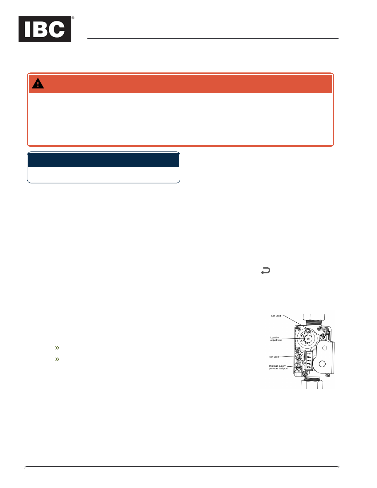
a. Compare the readings with Table 1 - Low Fire. If adjustment is necessary, remove the Low Fire
Adjustment cap to reveal a Torx head screw.
b. Make tiny adjustments, typically less than 1/8th of a turn at a time. Turn the screw clockwise to increase
CO2 and counter-clockwise to reduce CO2. If the target cannot be met, even after a half turn, contact the
factory.
c. When finished, replace the Low Fire cap, and leave the manual mode by pressing + AND -
simultaneously.
7. Switch off the unit by pressing the space above the dot.
8. Turn off the gas at the unit's gas shut-off valve.
9. Remove the flue gas analyzer from the test port, and reinstall the test port cap.
10. Remove the gas pressure manometer from the gas valve, and fully close the test port.
11. Turn on the gas at the unit’s gas shut-off valve.
12. Ensure there are no gas leaks before reinstalling the front cover.
13. Turn on the unit by pressing the space above the dot.
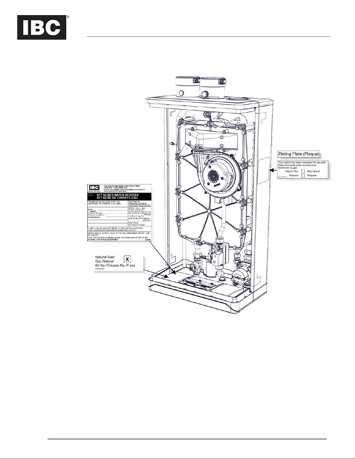
Completing and Affixing the Conversion Labels
1. Fill in the conversion labels (included in the kit) associated with the new fuel type.
2. Place the conversion labels onto the unit at the positions indicated on the last page.

Clocking the Meter (for Natural Gas only)
1. Turn off all other appliances and pilots.
2. Turn on the unit and set the unit to high fire.
3. Ensure the unit has a large load to heat, so that the unit will not shut off.
4. With a Stop-Watch, record the number of seconds for the smallest dial to make 1 full revolution.
5. CFH = (3600 x Dial Size) / Seconds
6. CFH x 1000 (check local Btu content) = Input Btu’s.
Note
For 2 PSI meters multiply CFH x 1.097
For Metric meters multiply CFH x 35.3
For 2 PSI metric meters multiply CFH x 1.097 x 35.3
For Altitude above 4,500’ deduct 2% per 1,000’ of altitude from the Input Btu’s.
6|

SFT 28-199 - Fuel Conversion to Natural Gas (LP to NG) Kit P-803 |7
Where to Place Conversion Labels on the Water Heater
Table of contents
Other IBC Industrial Equipment manuals
Popular Industrial Equipment manuals by other brands

Eaton
Eaton BBAOC-16 Instruction leaflet

ProMinent
ProMinent CHLORINSITU V operating instructions

Atlantic Boilers
Atlantic Boilers RS TURBOFLOW DN 32 S020+ operating & maintenance manual

GSi
GSi 2000 Series Operator's manual

Cincinnati
Cincinnati CL-7 Operation, safety and maintenance manual

AVL Looms
AVL Looms Little Weaver user manual