IBM 29 CARD PUNCH - User manual


IBY
/
FE
Supplement
Unit
29
Card Punch
Re:
Order
No.
S225-3357-3
This Supplement No.
SS23-4069
Date Novomber
23, 1970
Previous SupplementNos. None
\.
IBM FIELD ENGINEERING MAINTENANCE MANUAL
IBM
29
CARD PUNCH
.
@IBM
Corp.
1965, 1969
L
Pages to be inserted and/or removed are:
\-
Title Page, Preface
4-1
through
4-12
iii
through vi
4-17
through
4-22
1-9, 1-10 4-29, 4-30
1
2-3,
blank
4-35
through
4-41,
blank
3-1, 3-2 X-1
through
X-5,
blank
L,
3-5, 3-6
A change to the text
is
indicated by a vertical line to the left of the change; a changed or
added illustration
is
denoted by the symbol
to
the left of the caption.
C
Summary of Amendments
Maintenance Manual addition to list in Preface
L
Additional troubleshooting aids in Chapter
1
Lubrication changes in Chapter
3
Checkout procedure change in Chapter
2
L
Adjustment tolerance changes in Chapter
4
Figure
4-41
changed to improve figure-to-component association
C
Note: Please file this cover letter at the back of the manual to provide a record of
-
changes.
L
L
IBM Corporation,Product Publications, P.
0.
Box
390,
Poughkeepsie,
N.
Y.
I2602
\.


Field ~ngineerirbg
Maintenance Manual
2
Card Punch

S225-3357-3
FES: SS234069
Preface
This publicatibn provides information for the maintenance
of the IBM 29 Card Punch. The manual is written with
presupposition tfiifithe reader has a working knowledge of
the machine. As much applicable information as possible is
in each section of this manual. The sections are numbered
for easy reference. The sections are presented in a sequence
similar to the card path through the machine.
Timing adjustments for some units may vary among
machines due to features and engineering changes; refer to
the individual machine wiring diagram for accurate timing.
Special features are treated individually in a separate
manual, Field Engineering Theory
-
Maintenance,
IBM 29
Cad Punch Features, IBM 29 Interpreting Card Punch,
Model C,
S223-2926.
Other related manuals are:
Field Engineering Theory of Operation,
IBM 29 Card
Punch,
S225-3358
Illustrated Parts Catalog,
IBM 29 Card Punch,
S1244085
Reference Manual,
IBM 29 Card Punch,
GA24-3332
Field Engineering Maintenance Manual,
Motors, Genera-
tors, Relays, Circuit Breakers, Test Instruments, Miscella-
neous Components,
S225-3422
Fourth
Edition
(April 1969)
This a major revision of, and obsoletes, Form 225-3357-2, FE Supplement Form
S23-4035, and all earlier editions. Significant changes have been made throughout
this manual, including: new diagnostic flowcharts, Chapter 1; a new chapter,
Chapter 2; new lubricant specifications, Chapter 3;revised starwheel adjustments
and revised print suppress adjustments, Chapter
4.
This manual should be
reviewed in its entirety. Changes are periodically made to the specifications
herein; any such changes will be reported in subsequent revisions or FE
Supplements.
This manual has been prepared by the IBM Systems Development Division,
Product Publications, Dept B96, PO Box 390, Poughkeepsie,
N.Y.
12602.
A
form
for readers' comments is provided at the back of this publication. If the form has
been removed, comments may be sent to the above address.
@Copyright International BusinessMachines Corporation 1965, 1969
S225-3357-3
FES:
SS234069
Contents
.
Chapter
1
~derenceDataand Service Aids
....
1-1
.
Section
1
Reference Data
...........
1-1
1.1
Operations
............
1-1
1.2
Sequence of Operations
........
1-1
1.2.1
Functions
............
1-1
.
Section
2
Diagnostic Techniques
........
1-2
1.3
Initial Approach
...........
1-2
1.4
Diagnostic Flowcharts
.........
1-2
1.4.1
Start and Run Failures
.........
1-2
1.4.2
Card Transport Failures
........
1-2
1.4.3
Interposer Selection Failures
.......
1-2
1.4.4
Escapement Failures
.........
1-2
1.4.5
Punch Drive Cycle Failures
........
1-7
1.4.6
Printing Control Failures
........
1-7
1.5
Machine Service Features
........
1-7
1.5.1
Motor Switch
...........
1-7
1.5.2
Test Probe
............
1-7
1.6
ServicingTechniques
.........
1-7
1.6.1
Forcing
.............
1-7
1.6.2
Interrupting Machine Operation
......
1-8
1.6.3
Jumpering
............
1-8
1.6.4
Measuring
............
1-8
1.6.5
Cycling Manually
..........
1-10
1.6.6
Interchanging Units
..........
1-10
1.7
Difficult-to-Analyze and Intermittent Failures
. .
1-10
1.7.1
Left-Zero Feature
..........
1-11
1.7.2
Diagnosis of "Heavy" or Stiff Keyboards
...
1-11
1.7.3
Stacker
.............
1-12
1.7.4
Starwheel Adjustment
.........
1-12
Chapter
2
.
Consoleand Maintenance Facilities
. .
2-1
.
Section
1
Basic Unit
.....
:
......
2-1
2.1
installation
Procedures
.........
2-1
2.1.1
ShippingMaterial
..........
2-1
2.1.2
Power
..............
2-1
2.1.3
Keyboard Operations
.........
2-1
2.1.4
Program and Function (Model A)
......
2-1
2.1.5
Program and Function (Model B)
......
2-2
2.1.6
Final Checkout
...........
2-3
.
Section
2
Features
.............
2-3
2.2
Installation Procedures
.........
2-3
2.2.1
Feature Checkout
..........
2-3
2.2.2
Final Checkout
...........
2-3
Chapter
3
.
Preventive Maintenance
.......
3-1
Section
1
.
Basic Unit
............
3-1
3.1
Cleaning
.............
3-1
3.2
Adjustment
............
3-1
3.3
Safety
..............
3-1
3.3.1
Safety Devices
...........
3-1
3.3.2
Electrical Hazards
..........
3-1
3.3.3
Chemical Hazards
..........
3-1
3.4
Lubrication
............
3-1
Section
2
.
Features
.............
3-8
Chapter
4
.
Checks. Adjustments. and Removals
.
.
4-1
.
Section
1
Basic Unit
............
4-1
4.1
Base
..............
4-1
4.1.1
Diodes
.............
4-1
Arc Suppressors
...........
4-1
Drive
..............
4-1
Drive Motor
............
4-1
.......
Drive Motor Belt Adjustments
4-1
.....
Backspace Mechanism ServiceCheck
4-1
.....
Backspace Mechanism Adjustment
4-1
...........
Friction Drive
4-1
.......
Friction Drive ServiceCheck
4-1
Friction Drive Torque Adjustment
.....
4-2
Friction Clutch Removal
........
4-2
Escapement Unit
..........
4-2
EscapementUnitServiceCheck
......
4-2
Escapement Unit Adjustments
.......
4-3
Card Feed
............
44
Hopper Adjustments
.........
44
Feed Clutch Adjustment
........
44
Card Feed Latch Magnet Adjustments
....
4-5
Hopper-to-Prepunch Bed ServiceChecks
....
4-5
Pressure Rail Adjustments
........
46
Card Guide Adjustments
........
4-6
......
Card Registration Service Check
4-7
........
Pusher Arm Adjustment
4-7
.......
Card Stop Cam Adjustment
4-7
Pressure Roll ServiceCheck
.......
4-7
Pressure Roll Adjustments
........
4-7
Registration Adjustments
........
4-7
Feed Wheel Removal and Replacement
....
4-9
Card Feed Circuit Breaker Service Check
....
4-9
Card Feed Circuit Breaker Adjustment
....
4-9
............
Punch Drive
4-9
........
Index Pointer Adjustment
4-9
......
Interposer Magnet Adjustment
4-9
Guide Comb and Bumper Adjustment
....
4-9
Punch Interposer Magnet Assembly Adjustment
.
4-10
Interposer Bail Contact Assembly Adjustment
.
.
4-11
Punch Drive Removal and Replacement
....
4-11
Clutch Magnet Adjustment
........
4-12
.......
Punch Clutch Service Check
4-12
........
Punch Clutch Adjustments
4-13
High-speed CB Assembly ServiceCheck
....
4-14
....
High-speed CB Assembly Adjustment
4-14
High-speed Cam Removal
........
4-14
......
Die and Stripper Service Check
4-14
Die and Stripper Adjustment
.......
4-14
Die and Stripper Removal and Replacement
.........
(With Print Feature)
4-14
Die and Stripper Removal and Replacement
........
(Without Print Feature)
4-14
......
Punch Penetration Adjustments
4-15
...
Punch Removal and Replacement
...
Pin Bail Drive Link Adjustment
Pin-Sense Unit
........
...
Pin-SensingUnit ServiceChecks
....
Pin-SensingUnit Adjustments
Pin-Sensing Unit Removal and Replacement
Sensing Pin Removal
......
Eject Unit
.........
EjectUnitAdjustrnents
......
.........
Stacker Unit
Stacker Unit Adjustments
.....
iii
........
Program Drum Unit
Sensing Assembly Service Check
....
....
SensingAssembly Adjustments
SensingAssembly Removal and Replacement
Program Cam ContactsService Check
.
.
...
Program Cam Contacts Adjustment
Program Drum
interlock
Arm (Split Hub)
.........
Adjustment
..........
Print Unit
Print Assembly Servicechecks
...
Print Assembly Adjustments
.....
Print Assembly Removal and Replacement
.
Ribbon Feed Pawl Adjustment
....
Print Drive Adjustment
.......
Print SuppressMagnet Adjustment
...
Keyboard
...........
Contact Adjustments
.......
Hook Support Bar Adjustment
....
Permutation Bar Adjustment
.....
Restoring Magnet Adjustment
.....
l
llustrations
Figure Title
Chapter
1
.
Reference Data and Service Aids
1-1 Characteristics
.........
1-2 Operations
..........
1-3 Sequence of Operations
......
.....
1-4 Diagnostic Flowchart Symbols
1-5 Start and Run Failures
.......
......
1-6 CardTransportFailures
1-7 lnterposer Selection Failures
.....
....
1-8 Escapement Failures (Part 1 of 2)
....
1-8 Escapement Failures (Part
2
of 2)
1-9 Punch Drive Cycle Failures
.....
1-10 Print Control Failures
.......
1-11 Test Probe
..........
1-12 Reed Relay
insertion
.......
Page
...
1-1
..
1-1
..
1-2
...
1-2
...
1-3
..
1-4
..
1-5
. .
1-6
..
1-7
..
1-8
...
1-9
..
1-10
..
1-10
Chapter
2
.
Consoleand Maintenance Facilit'm'
2-1 Program Card
.
Model A
.........
2-2
2-2 Program Card
.
Model B
.........
2-2
Chapter
3
.
PreventiveMaintenance
3-1 Preventive Maintenance Routines
.......
3-2
3-2 Lubrication
.
Right Front
.........
3-3
.
3-3 Lubrication Front
..........
3-4
3-4 Lubrication
.
Front (Machine Bed Tilted)
....
3-5
3-5 Lubrication
.
Rear 3-6
...........
3-6 Punch Unit Lubrication
.........
3-7
3-7 Keyboard Lubrication
..........
3-8
Chapter
4.
Checks. Adjustments. and Removals
4-1
Friction Drive Adjustment
.........
4-1
4-2 Escapement Adjustment (Part 1 of 2)
.....
4-2
4-2 Escapement Adjustment (Part 2 of 2)
.....
4-3
4-3 Hopper Adjustment
............
4-4
4.12.5 Upper Permutation Support Adjustment
....
4-39
.........
4.12.6 Key Unit Adjustment 4-39
4.12.7 Key Unit Removals
..........
4-40
Section 2
.
Features
.............
4-41
.
........
Chapter
5
Power Supplies
5-1
Section 1
.
Basic Unit
............
5-1
Section 2
.
Features
.............
5-1
Chapter
6
.
Locations
...........
6-1
6.1 Keystem Numbering
.........
6-1
6.2 Reed-Relay Card
........
6-1
6.2.1 Reed Relays
.........
6-2
6.3 Wirecontact Relays
.........
6-3
6.4 Standard Modular System (SMS)
......
6-3
6.4.1 SMS Card Receptacles
.........
6-3
6.4.2 SMS Locations and Pin Numbering
....
6-3
6.5 Location Figures
..........
6-5
lndex
................
X-
1
Figure Title
CF Clutch Magnet Adjustment
...
CF Clutch Adjustment
......
CF Latch Magnet Adjustment
....
Pressure Rail Adjustment
.....
Pressure Rail
.
Card-Lever Contact
. .
Card Guide
.
Detail Station
....
Card Guide
.
Master Station
....
.....
Detail Card Registration
.....
Pressure Roll Adjustment
Master Station Registration Adjustment
.
....
Armature Pivot Adjustment
Armature Pivot Adjustment
.
Side View
......
ArmatureAdjustment
Interposer Unlatching Clearance
...
lnterposer Relatching Adjvstment
.
.
Armature Unlatching Clearance
...
lnterposer Bail Contact Adjustment
.
.
lnterposer Bail Contact Rise Adjustment
Print Drive Unit Cam Timing
....
PunchClutchhlagnet
......
Punch Clutch Components
.....
PunchClutchAdjustment
.....
....
High-SpeedCircuit Breaker
.
.....
Punch Bed Front View
PunchandExtension
......
Punch Penetration Adjustment
...
Sensing Pin Contact Adjustment
...
Pin Sensing Adjustment
......
........
Stacker Timing
.......
Stacker Adjustment
TravelingCardCuide
......
Timing Tool
.........
Program Unit Timing Chart
....
Page
.4-5
1
.4-5
.4-5
.4-6
4-6
-
.4-6
.4-7
.4-7
.4-8
..
.4-8
.4-9
.4-9
.
4-10
.
4-10
.
4-10
.
4-11
.
4-11
.
4-11
.
4-12
.
4-12
.
4-13
.
4-13
.
4-14
-
.
4-15
.
4-15
.
4-16
.
4-17
.
4-17
.
4-1C
.
4-19
..
.
4-19
.
4-20
.
4-21
Figure Title
4-37 Method of HoldingEscapement Wheel
4-38 Program Cam Contact Adjustment
.
....
4-39 OverlayforFigure4-40.
.....
4-40 Code Plate Chart E'L'
....
441 Print Interposer Assembly
442 Punch Drive and Yoke Adjustments
.
4-43 Printing Adjustment
.....
4-44 Print Interposer Assembly
....
445 Vertical Drive Rod Assembly
...
....
4-46
CharacterPatternsE'L1.
....
447 CharacterPatternsE'A'.
448 Test Patterns.
.......
449 Print Drive Unit
.......
4-50 Print HeadRemoval.
.....
4-51 Print Wire Replacement
....
4-52 Print Suppression Magnet Adjustment
4-53 Keyboard Adjustment
.....
4-54 Keyboard Permutation Unit
-
Rear
.
4-55 Keyboard Permutation Unit
-
Bottom
A
alpha
AMP
auto
CB
CE
CEM
CF
chat
ckt
col, cols
ctrl
dc
def
dup
HSS
L
Hz
ampere
alphabetic
amphenolpin
automatic
Page
...
.4-21
.....
4-23
....
4-25
....
.4-27
.....
4-29
.....
4-29
....
.4-30
.....
4-30
.....
4-31
.
.
;
.
.4-32
.....
4-33
....
.4-34
....
.4-34
....
.4-35
....
.4-36
...
.4-36
.....
4-37
....
.4-38
.....
.439
circuit breaker
customer engineer
Customer Engineering Memorandum
card feed
character
circuit
column, columns
control
direct current
definition
duplicate
friction clutch
high-speed
skip
Hertz (cycles per second)
Figure Title
4-56 Keyboard Key Unit and Permutation Unit
. .
.......
4-57 Keyboard Interlock Disks
Chapter
5.
Power
Supplies
..........
5-1 Power Supply
5-2 Power and Receptacle Requirements
....
Chapter
6.
Locations
Combination and Numeric Keystem Numbering
Locations
-
Relay Board and Relays
....
.......
SMS Printed WiringCards
WireContact Relay Machine Relay Gate
-
Card
...........
Side View
Locations
-
Front View
.......
Locations
-
Rear View (Reed-Relay Machine)
.
Locations
-
Rear View (Wire-Contact Relay
...........
Machine)
.........
Locations
-
Rear
Locations
-
Front
.........
IBC
intlk
LZ
max
ms
MULT PCH
NC
NO
No.
num
FCC
PM
Prgm
sec
SMS
v
interposer bail contact
interlock
left zero
maximum
millisecond
multipunch
normally closed
normally open
number
numeric
program cam contact
preventive maintenance
ProkTm
second
Standard Modular System
volt
Page
. .
440
. .
441
Abbreviations
5225-3357-3
FES:SS234069
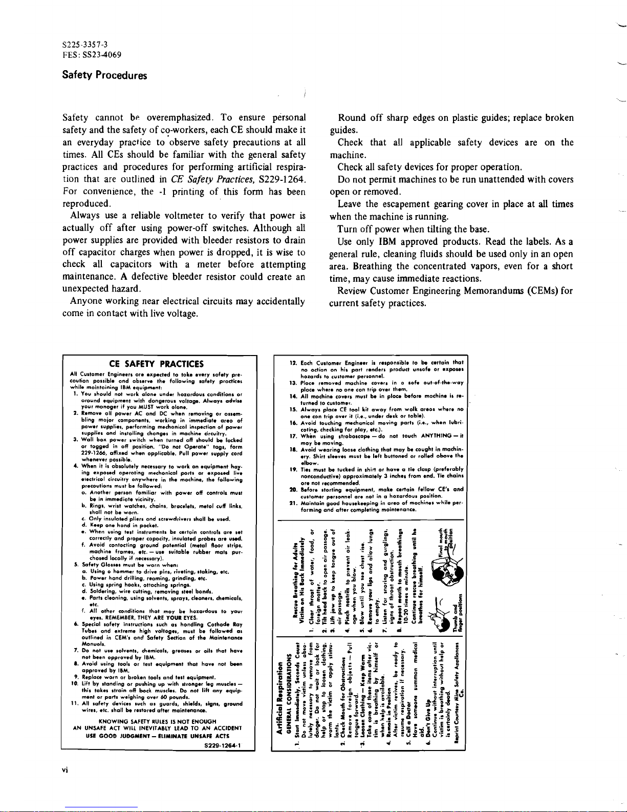
Safety Procedures
Safety cannot be overemphasized. To ensure personal
safety and the safety ofco-workers, each CE should make it
an everyday practice to'observe safety precautions at all
times. All CEs should be familiar with the general safety
practices and procedures for performing artificial respira-
tion that are outlined in
CE
Safety Practices,
S229-1264.
For convenience, the
-1
printing of this form has been
reproduced.
Always use a reliable voltmeter to verify that power is
actually off after using power-off switches. Although all
power supplies are provided with bleeder resistors to drain
off capacitor charges when power is dropped, it is wise to
check all capacitors with a meter before attempting
maintenance. A defective bleeder resistor could create an
unexpected hazard.
Anyone working near elect~icalcircuits may accidentally
come in contact with live voltage.
Round off sharp edges on plastic guides; replace broken
guides.
Check that all applicable safety devices are on the
machine.
Check all safety devices for proper operation.
Do not permit machines to be run unattended with covers
open or removed.
Leave the escapement gearing cover in place at all times
when the machine is running.
Turn off power when tilting the base.
Use only IBM approved products. Read the labels. As a
general rule, cleaning fluids should be used only in an open
area. Breathing the concentrated vapors, even for a short
time, may cause immediate reactions.
Review Customer Engineering Memorandums (CEMs) for
current safety practices.
CE SAFETY PRACTICES
All Cu~tomerEngineers ore .xp.cted to toke every sofety pre.
caution po~~ibleond observ. the following safety procticas
while mointoining IBM equipmant:
1.
You should not work alone undar
hazardous
conditions or
oround equipment with
dangerous
voltage. Always adrim
your monoger if you MUST work olon..
2.
Remove oll power AC ond DC when removing or ossem-
bling moior components, working in immediate areo of
power supplies, performing mechonicol inspectionof power
supplies ond instolling chonges in machine circuitry.
3.
Wall box power switch when turned off should be locked
or togged in off position. "Do not Operat." togs, form
229-1266,
ofixed when opplicoble. Pull power supply cord
whenever possible.
4.
When it is
absolutely
necessary to work on equipment har
ing exposed
operating
mcchonical ports or expo~dlire
electrical
circuitry anywhere in the mochine. the following
precautions
must be followed:
o. Another person fomiliar with power off controls must
be in
immediate
vicinity.
b. Rings, wrist watches, chains, bracelets, met01 cuff links,
sholl not be worn.
c. Only
insulated
pliers ond screwdrivers shall be used.
d. Keep one hond in pocket.
e.
When u~ingtest
instrument^
be artoin controls are set
correctly and proper copocity, in~ulatedprobes ore uud.
f. Avoid rontocting ground potential (metal floor strips,
machine frames, etc.
-
use suitable rubber mots pur-
chased
locolly if necessary).
5.
Safety Glos~esmuat be worn when:
a. Using o hommer to drive pins, riveting, stoking, etc.
b. Power hond drilling, reoming, grinding, etc.
c. Using apring hook,, ottoching springs.
d. Soldering, wire cutting, removing steel bond*.
e. Ports cleoning, using solvents, sprays,
cleaners.
chemicals,
.tC.
f.
All other wnditbns thot moy be ho~ordousto your
eyes. REMEMBER, THEY ARE YOUR EYES.
6.
Special softly instructions such as hondling Cothode Ray
Tubel ond extreme high voltogea, must be followed
01
outlined in CEM's ond Safety Section of the Maintenance
Monuols.
7.
Do not
use
solvents, chemicals, greases or oils that hove
not been opproved by IBM.
8.
Avoid wing tools or test equipment thot hove no1
b..n
approved by IBM.
9.
Replace worn
ar
broken tools and test equipment.
10.
Lift by standing or pushing up with stronger leg muscles
-
this tokes strain off bock muscles. Do not liH any equip-
ment or ports weighing over
60
pounds.
11.
All safety devices such as guards, shields, signs, ground
wires, ctc. shall be restoredofter maintenonu.
KNOWING SAFETY RULES IS NOT ENOUGH
AN UNSAFE ACT WILL INEVITABLY LEAD TO AN ACCIDENT
USE
GOOD
JUOGMENT
-
ELIMINATE UNSAFE ACTS
S229-1264-1
12.
Each Customor Enginoer in
responsible
lo be cortain that
no oction on his part renders product unsofo or exposel
hozards to customer personnel.
13.
Ploce removed machine covers in o sofe out-of-the-way
ploce where no one con trip over them.
14.
A11 mochin. covers mull be in ploce before mochino is re-
turned to customer.
15.
Always CE tool kit awoy from wolk oreos where no
one con trip
over
it (i.4.. under desk or loblo).
16.
Avoid touching m.chanicol moving ports (i.e., when lubri-
coting, checkingfor play, etc.).
17.
Whin using stroboscope-do not touch ANYTHING- it
moy be moving.
la.
Avoid wearing loose clothing thot may be cought in machin.
err. Shirt sleeves mu11 be left buttoned or rolled obove the
elbow.
19.
Ties must be tucked in shirt or hove a tie clasp (preferably
nonconductive) opproximotely
3
inches from end. Tie chain1
ore not recommended.
110.
Befor. storting equipment, make certain fellow CE's and
customer personnel ore not in a horardous position.
21.
Maintaingood housekeeping in oreo of mochines while per-
forming and after completing mointenonce.
L
.i.i
.
rid
h:
d
-
"r'd
Chapter
1.
Reference Data and
SerLice
Aids
Section
1.
ReferenceData
4.
Card Transport:
Mechanical control of the movement of
the card through the machine.
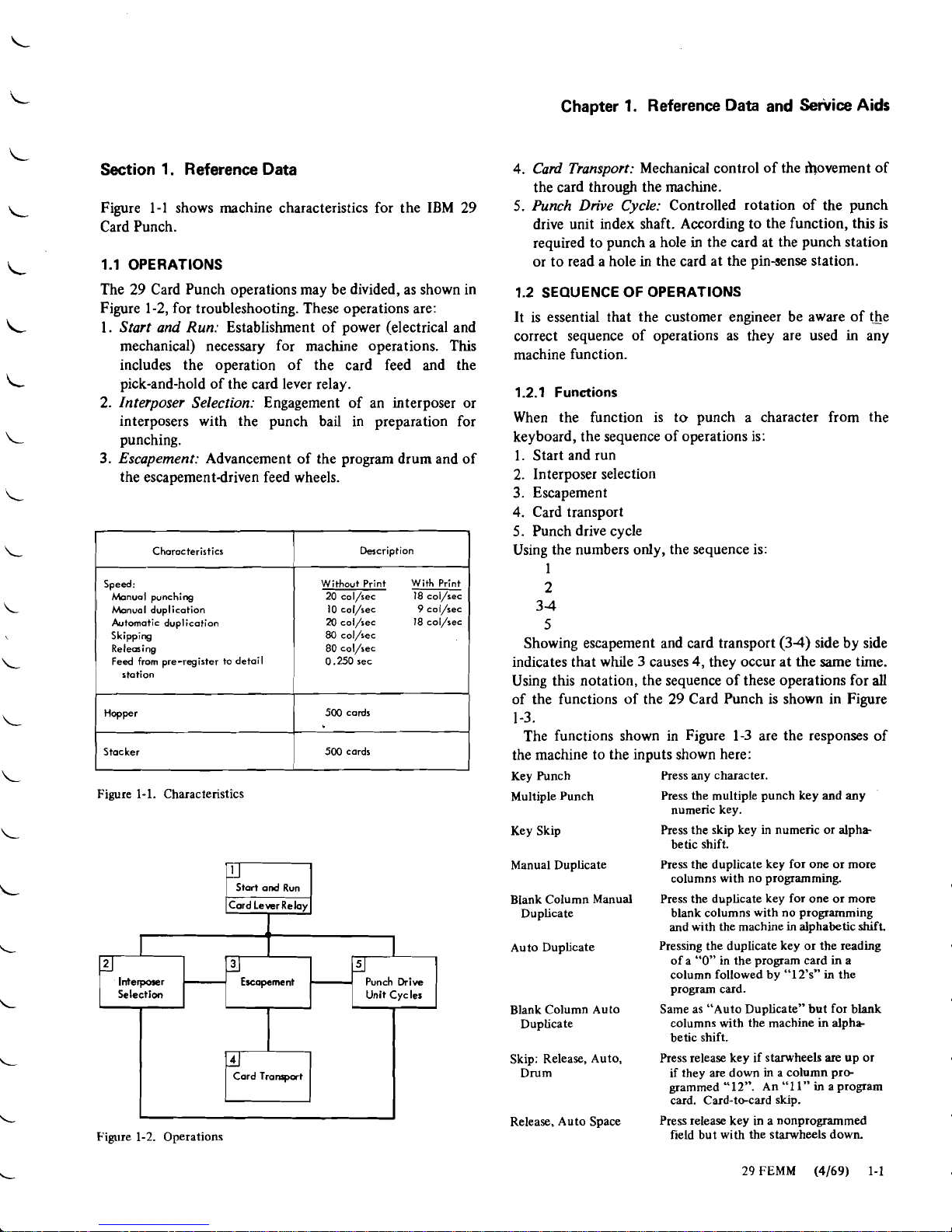
Figure 1-1 shows machine characteristics for the IBM 29
5.
Punch Drive Cycle:
Controlled rotation of the punch
Card Punch. drive unit index shaft. According to the function, this is
required to punch a hole
in
the card at the punch station
1.1 OPERATIONS
or to read a hole
in
the card at the pin-sense station.
The 29 Card Punch operations may be divided, as shown in
Figure 1-2,for troubleshooting. These operations are:
1.
Start and Run:
Establishment of power (electrical and
mechanical) necessary for machine operations. This
includes the operation of the card feed and the
pick-and-hold of the card lever relay.
2.
Interposer Selection:
Engagement of an interposer or
interposers with the punch bail in preparation for
punching.
3.
Escapement:
Advancement of the program drum and of
the escapement-driven feed wheels.
1
Chorocteristics
I
Description
I
Speed:
Manuol punching
Manual duplication
Automatic duplication
Skipping
Releasing
Feed from pre-register to detail
station
Without Print With Print
20 col/sec
18
col/sec
10 col/sec
9
col/sec
20
col/sec
18
col/sec
80
col/sec
80 col/sec
0.250 sec
/
500
cords
I
1
Stacker
1
500
cards
I
Figure
1-1.
Characteristics
I
Figure
1-2.
Operations
Interposer
Selectian
1.2 SEQUENCE OF OPERATIONS
It is essential that the customer engineer be aware of the
correct sequence of operations as they are used
in
any
machine function.
I I I
Escapement
1.2.1 Functions
Punch
Drive
Unit Cycles
When the function is to punch a character from the
keyboard, the sequence of operations is:
1. Start and run
2.
Interposer selection
3.
Escapement
4.
Card transport
5.
Punch drive cycle
Using the numbers only, the sequence is:
1
2
34
5
Showing escapement and card transport (34) side by side
indicates that 'hile 3 causes
4,
they occur at the same time.
Using this notation, the sequence of these operations for
all
of the functions of the
29
Card Punch is shown in Figure
1-3.
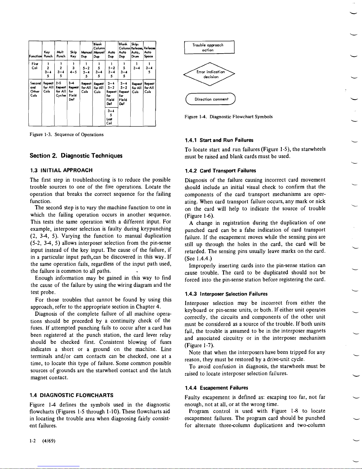
The functions shown in Figure 1-3 are the responses of
the machine to the inputs shown here:
Key Punch Press any character.
Multiple Punch Press the multiple punch key and any
numeric key.
Key Skip Press the skip key in numeric or alpha-
betic shift.
Manual Duplicate Press the duplicate key for one or more
columns with no programming.
Blank Column Manual Press the duplicate key for one or more
Duplicate blank columns with no programming
and with the machine
in
alphabetic
shift.
Auto Duplicate Pressing the duplicate key or the reading
of a
"0"
in the program card
in
a
column followed by "12's" in the
program card.
Blank Column Auto Same as "Auto Duplicate" but for blank
Duplicate columnswith the machine
in
alpha
betic shift.
Skip: Release, Auto, Press release key if starwheels
are
upor
Drum if they are down in a column pre
grammed
"1
2".
An
"1
1"
in a program
card. Card-tecard skip.
Release, Auto Space Press release key in a nonprogrammed
field but with the starwheels down.
29
FEMM (4169)
1-1
Blank
Column
(
Direction comment
)
iunctlon
Col
Second
ond
Other
Cols
Figure
1-4.
Diagnostic Flowchart Symbols
Blank
Column
Figure
1-3.
Sequence of Operations
Key
Punch
2
3-4
5
Repsot
forAll
Colr
Section
2.
DiagnosticTechniques
Skip:
Release,
1.3 INITIAL APPROACH
Release
The first step in troubleshooting is to reduce the possible
trouble sources to one of the five operations. Locate the
operation that breaks the correct sequence for the failing
function.
The second step is tovary the machine function toone in
which the failing operation occurs in another sequence.
This tests the same operation with a different input. For
example, interposer selection is faulty during keypunching
(2, 34, 5). Varying the function to manual duplication
(5-2, 34,5) allows interposer selection from the pin-sense
input instead of the key input. The cause of the failure, if
in a particular input path,can be discovered in this way. If
the same operation fails, regardless of the input path used,
the failure is common to all paths.
Enough information may be gained in this way to find
the cause of the failure by using the wiring diagram and the
test probe.
For those troubles that cannot be found by using this
approach, refer to the appropriate section in Chapter 4.
Diagnosis of the complete failure of all machine opera-
tions should be preceded by a continuity check of the
fuses. If attempted punching fails to occur after a card has
been registered at the punch station, the card lever relay
should be checked first. Consistent blowing of fuses
indicates a short or a ground on the machine. Line
terminals and/or cam contacts can be checked, one at a
time, to locate this type of failure. Some common possible
sources of grounds are the starwheel contact and the latch
magnet contact.
Mult Skip
Punch Key
1.4 DIAGNOSTIC FLOWCHARTS
Figure 14 defines the symbols used in the diagnostic
flowcharts (Figures 1-5through 1-1
0).
These flowcharts aid
in locating the trouble area when diagnosing fairly consist-
ent failures.
knml
Dy
First1111I111I
5-2
3-4
Raped
forAll
Cols
2
3-4
5
2-5
Rspmt
krAll
Cycla
1.4.1 Start and Run Failures
To locate start and run failures (Figure 1-5), the starwheels
must be raised and blank cards must be used.
3
4-5
3-4
Revt
for
Field
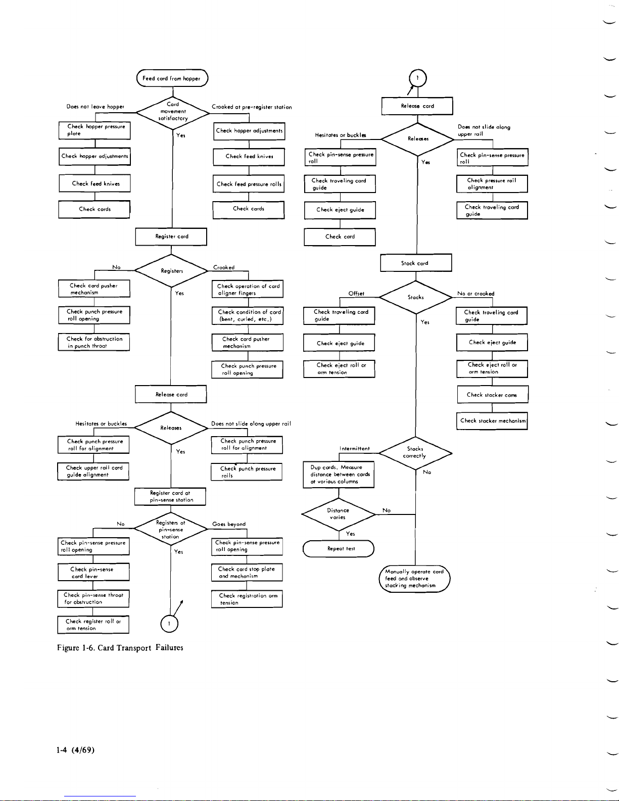
1.4.2 Card Transport Failures
Diagnosis of the failure causing incorrect card movement
should include an initial visual check to confirm that the
components of the card transport mechanisms are oper-
ating. When card transport failure occurs, any mark or nick
on the card will help to indicate the source of trouble
(Figure 1-6).
A
change in registration during the duplication of one
punched card can be a false indication of card transport
failure. If the escapement moves while the sensing pins are
still up through the holes in the card, the card will be
retarded. The sensing pins usually leave marks on the card.
(See 1.4.4.)
Improperly inserting cards into the pin-sense station can
cause trouble. The card to be duplicated should not be
forced into the pin-sense station before registering the card.
~onu.1) Auto
1.4.3
l
nterposer Selection Failures
Auto
Dup
5
3-4
3-4
5-2
R-t
for
Dy
5
3-4
Revt
forAll
Cols
Interposer selection may be incorrect from either the
keyboard or pin-sense units, or both. If either unit operates
correctly, the circuits and components of the other unit
must be considered as a source of the trouble. If both units
fail, the trouble is assumed to be in the interposer magnets
and associated circuitry or in the interposer mechanism
(Figure 1-7).
Note that when the interposers have been tripped for any
reason, they must be restored by a drive-unit cycle.
To avoid confusion in diagnosis, the starwheels must be
raised to locate interposer selection failures.
Dy
5-2
3-4
5555
3-4
5-2
Rspeot
fa
1.4.4 Escapement Failures
Auto,
Dru
3-4
Rspmt
forAll
Cols
Faulty escapement is defined as: escaping too far, not far
enough, not at all, or at the wrong time.
Program control is used with Figure 1-8 to locate
escapement failures. The program card should be punched
for alternate threecolumn duplications and twocolumn
Auto
SPu
3-4
5
Repmt
forAll
Colr

Slowly or overheah No
I
I
(
Check motor start relay
1
Check mainline voltage
Check motor
I
Release ond feed card
a
Check mainline
furer
a
Check motor stort relay
a
Check motor
I
I
I
Check wnchclutch
I
operation
1
Cord ir not fed to pre-register $totion Drum doer not go to column
1
Check cord feed clutch
mechanism
I
Check CF clutch magnet
a
Check cord feed mechanism
Check card lever operation
cord tronrport flowchart
I
Register the cord and
space out
Check skip relay
'-4
to ercopement flow-
chart (Figure 1-8)
Doer not register Nospacing
or
punch drive cycles
Check CF latch mechanism
L
t
I
(
Check CF latchmagnet
/
Check cord lever contact
rl
f
Notrouble found, go
to
ercopement flowchart
(Figure
1-8)
if
no
rpocing,
or
go to
~unchdrive cycler
flowchart (Figure
1-91
ifno punch drive cycles
Figure
1-5.
Start and Run Failures
L
29
FEMM
(4169)
1-3
Feed card from hopper
+
Doer
no1
leave hopper movement Crooked ot pre-register station
$atisfactory
Check hopper pressure
plate Check hopper adjustments
1
Release cord
1
Donnot slide along
Hesitater
or
buckln upper rail
Releeer
Check pin-senre preuure Check pin-$eweprerrvre
Check hopper adjustments
-
Check troveling card Check prnsure roil
Check feed knives
I
I
Check feed pressure rolls
I
Check eject guide Check troveling card
Register card
a
Check card
CI
Regirterr Crooked
Check cord pusher Check operotion
of
cord
mechanism oligner fingers
Stock cord
u
Offset Stocks
No
or
crooked
Check trwcling card Check troveling cord
guide guide
roll opening (bent, curled, etc.)
Check for obstruction Check card pusher
in
punch throot
I
Chcck eject guide
I
I
Check eject gvide
I
Check eject roll or Check
eject
roll
or
roll opening
Releme card
I
Check stocker cons
u
Heritat-
or
buckles
I.
-oes not slide
along
upper rail
-7
Check stacker mechonirm
D
Check punch pressure
roll for nlignment
Dup cards.
Measure
\
at
various
columns
No
Goes beyond
I
I
Check pin-senre prerwre
I
I
Check pin-sense pressure] Repeot test
m
I
roll o~enina
I
roll opening
I
feed
ond
observe
stacking mechanism
Check regirtrotion orm
I/
Figure
1-6.
Card
Transport Failures

and olphobatic
character
keys
Check interposer relotch
a
Check keyboardrestore No
selected
Check interposer relotch Check interpan magnet
Check pin-sere contoch
v
Check cornmar bar
=?
Check throot plates and
Check inkrpoler
Check keybodshift ckt
w
Check
for
mopat impulse.
If
no
~ulre,proceed
to
Check kybordcontoch
1
Check mtorecircuit
a
Check pin-tare contoch
+
Check rmingpin
=7
Check codregirtrotion
Figure
1-7.
Interposer Selection Failures
29
FEMM
(4169)
1-5

A. Alphabetic Duplicate switch off. kev duo
.,,
(
olphobetic and blank
)
Extra column
or
ot wrong time
Check 12 program contact and circuit
Check dup reloy retup
Check PI cam contact Check escape circuit
to interposer selection
flowchart (Figure 1-7)
0. Numeric
Duplicate
and Skip
Yer
auto dup 011 I2digits,
Perform Bond C
Check dup relays
a
Check dup circuits
-
No
trouble found, go
(-1
to interposer selection
flowchart (Figure 1-7)
Too far No Yer (nicked
or
torn holer)
Check retup of IBC
-
Yes
I
Check ercope circuit
I
No
to interpmer selection
flowchort (Figure 1-7)
Perform A and C
C
Check escapement
interlock relay
Check PI cam contact
Check that punch
interposer is
engaging bail
I
Figure
1-8.
Escapement Failures (Part
1
of
2)
Check
0
pragrom cantoct
Check auto rkip/dup
switch
Check dup reloy
I
I
Check PI timing and
duration Check 12 program contoct
Check punch clutch
Check escape interlock
relay
Check dup relor
Check dup circuit

C.
Ksv
Punch
Perform
A
and
B
Check escape
mechanism
Tm
far
No
I
Check drive
gsa
train
+
Check FC torque
Check
PI
cam contact
Check
FC
torque
or
escape
mognet
onolyre original
foiling condition
I
I
Figure
1-8.
Escapement
(Part
2
of
2)
skips through column 38. This is followed by a 25column
skip (ending
in
column 63), an llcolumn alphabetic
duplication, a Scolumn skip, and duplication of column
80.
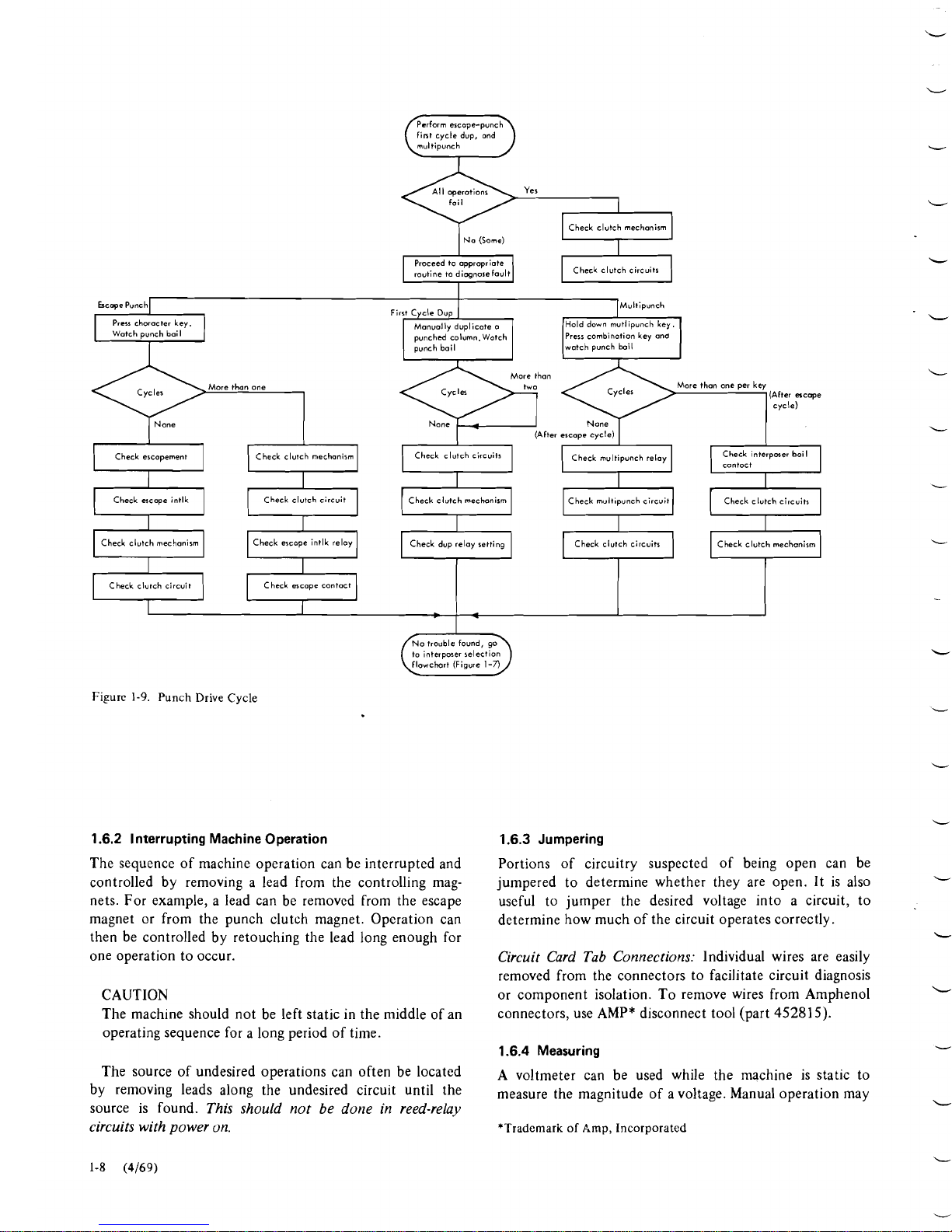
1.4.5 Punch Drive Cycle Failures
Locate punch drive cycle failures with the starwheels raised
(Figure 1-9). Diagnosis of clutch failures should include an
initial manual cycle of the punch drive unit. Incorrect
clutch overthrow or a defective detent can be found while
performing this operation
1.4.6 Printing Control Failures
The program card used for locating escapement failures can
be used for locating programmed printing failures. Diagnos-
tic flowchart is Figure 1-10.
1.5 MACHINE SERVICE FEATURES
The 29 Card Punch has two diagnostic features that have
been incorporated to aid the customer engineer. These are:
Motor switch
Test probe
1.5.1 Motor Switch
The motor switch turns the motor off and allows other
areas of the machine to remain energized. It is useful when
manually cycling the machine. Some adjustments are made
with the motor stopped.
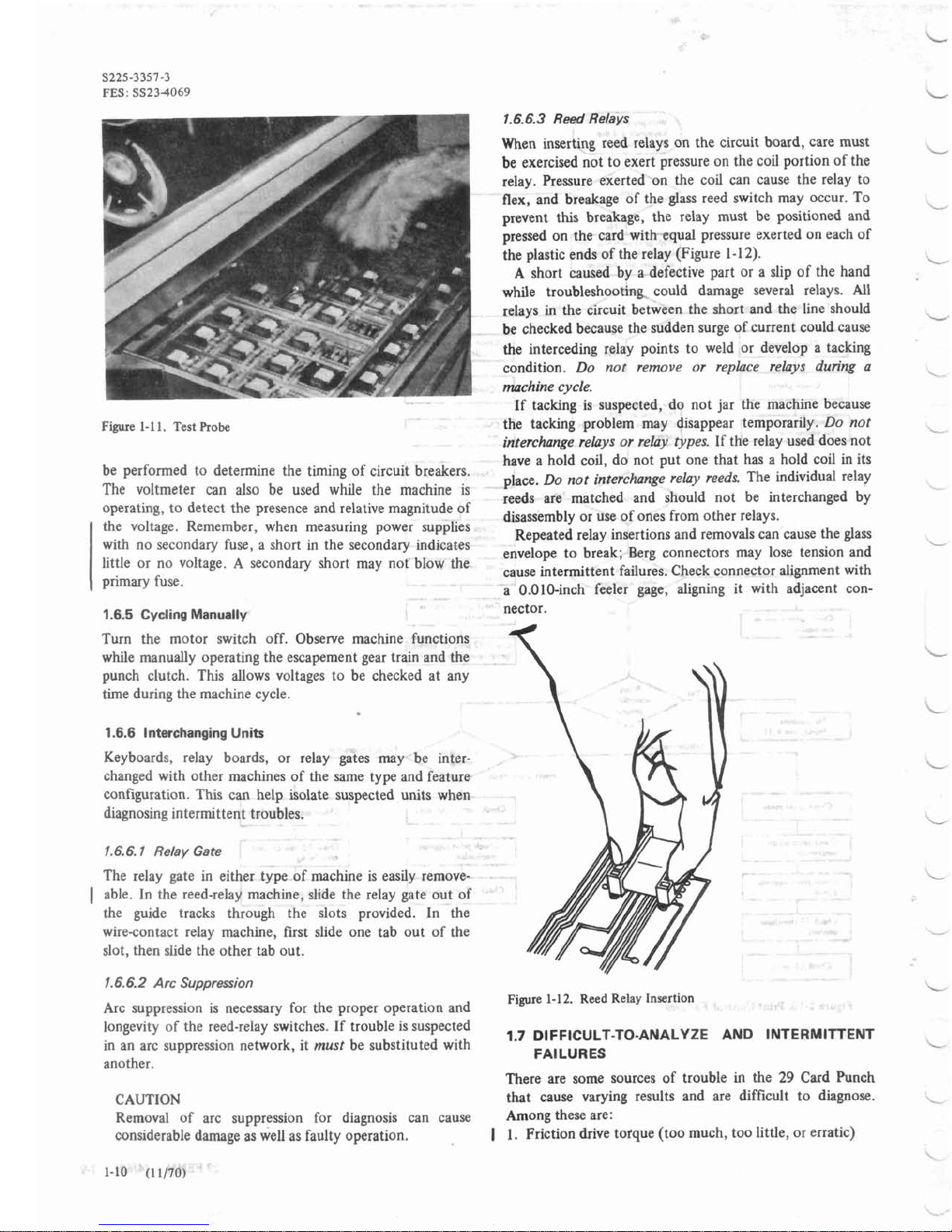
1.5.2 Test Probe
The test probe (Figure 1-1
1)
contains a neon indicator in
series with
a
resistor. One lead of the indicator is connected
to the power supply. The other lead is used to trace circuits
leading tocoils or magnets. A jack is provided on the power
supply chassis.
CAUTION
Care must be used when probing relay points because the
point of the probe might spread the pin connectors and
cause the reed switch to make poor contact or break the
pin. Be careful in the use of the test probe; an accidental
short could tack several relay points. The probe should
not be used to estimate circuit voltages. Use the meter for
voltage measurements.
Reed relays should be probed through the top of the
bobbin because the vertical rows of holes on the land
pattern for a particular relay position do not, in all cases,
connect to the relay connector.
Note: When probing P3, a false indication may occur; P3
appears not to make. This is due to the timing relationship
between the short duration of P3
(7
ms) and the 60-Hz
negative line pulse used to bias the probe.
1.6 SERVICING TECHNIQUES
1.6.1 Forcing
Extra pressure can be applied to various components to
simulate malfunction. For example, the friction drive can
be forced or retarded manually at the top of the program
drum, or finger pressure can be applied to the escape
magnet armature tohelp or hinder its operation. Magnetism
of the escape magnet can be detected, and its strength
estimated with any lightweight steel blade (screwdriver or
burnishing tool).
29
FEMM
(4169)
1-7
fint cycle dvp, ond
multipunch
I
Na
(Some)
v
routine to dimnose fault Check clutch circuits
Multipunch
punched column.Watch
Prerr
combination key
and
punch bail watch punch boil
Prcsr
character
key.
Cycler
More
than
one
per key
cycle)
I
(After ercape cycle)
I
I
Check ercopement Check clutch rnechanirm
1
Check clutch circuits
I
(
Check multipunch relay Check interpaer bail
I
Ic~"toCt
Check escope intlk Check clutchmechanism Check multipunch circuit Check clutch circuits
Check clutch mechanism
a
Check dup relay setting Check clutch circuits Check clutch mechonirm
Check clutch circuit Check escape contact
to interposer relection
flowchart
(Fioure
1-n
Figure
1-9.
Punch Drive Cycle
1.6.2 InterruptingMachine Operation 1.6.3 Jumpering
The sequence of machine operation can be interrupted and
controlled by removing a lead from the controlling mag-
nets. For example, a lead can be removed from the escape
magnet or from the punch clutch magnet. Operation can
then be controlled by retouching the lead long enough for
one operation to occur.
Portions of circuitry suspected of being open can be
jumpered to determine whether they are open. It is also
useful to jumper the desired voltage into a circuit, to
determine how much of the circuit operates correctly.
Circuit Card Tab Connections:
Individual wires are easily
removed from the connectors to facilitate circuit diagnosis
or component isolation. To remove wires from Amphenol
connectors, use AMP* disconnect tool (part
452815).
CAUTION
The machine should not be left static in the middle of an
operating sequence for a long period of time.
1.6.4 Measuring
The source of undesired operations can often be located
by removing leads along the undesired circuit until the
source is found.
This should not be done in reed-relay
circuits with power on.
A voltmeter can be used while the machine is static to
measure the magnitude of a voltage. Manual operation may
*Trademark of Amp, Incorporated

kypunch
and
dup
all chamctan
Prink
Chock print wppms
mechanism
With print switch
on
md
stamheals up, ke+unch
I
adprint al; ~horiton
1
Check platen
Q
Wrong, smudgy, or
toa
light No
I
for
obstruction
Check ribbon
chomcterr under progrom
control
Check print suppras
circuit
Check print switch
Q
I
I
I
Chock print switch
I
Check pintdrive
No
Check print relay
contach
I
Check print wpposs
magnet circuih
f-l
Ym
Ym
No
Notroubles
found, see
4.11
Extranwm
xua
No lmt chaacter
Invufficient zem
Chock print relay pick
circuit
Check print relay
-
Check print suppress
I
Cbck print suppress
I
circuit
I
Check
I2
stowh..l
Check print suppress
mochmim
Chock print supprau
I
Ckk
LZ
switch
I
No
Chak card
Iwu
relay
a
mechanism
Check ac-o interlock
a
I
Check
12
programcontac
(pint relay hold circuit)
Chak
U
print switch
m
CWpintrelay
m
Figure
1-
10.
Print Control
Failures
29
FEMM
(4169) 1-9
S225-3357-3
FES:
SS234069
Figure
1-1
1.
Test Probe
1.6.6.3
Reed
Relays
When inserting reed relays on the circuit board, care must
be exercised not toexert pressure on the coil portion of the
relay. Pressure exerted on the coil can cause the relay to
flex, and breakage of the glass reed switch may occur. To
prevent this breakage, the relay must be positioned and
pressed on the card with -equal pressure exerted on each of
the plastic ends of the relay (Figure 1-12).
A short caused by a defective part or a slip of the hand
while troubleshooting could damage several relays. All
relays in the circuit between the short and the line should
be checked because the sudden surge of current could cause
the interceding relay points to weld or develop a tacking
condition.
Do nor remove or replace relays during a
machine cycle.
If tacking is suspected, do not jar the machine because
the tacking problem may disappear temporarily.
Do not
interchanfe relnys or relay
types.
If the relay used does not
-
.
.-
have a hold coil, do not put one that has a hold coil in its
be performed to determine the timing of circuit breakers. place.
DO
not interchange relay reeds
The individual relay
The voltmeter can also be used while the machine is
reeds
are
matched
and
should
not
be
interchanged
by
operating, to detect the presence and relative magnitude of disassembly or use of ones from other relays.
Ihe "Itage'
Remember.
when
measuring power Repeated relay insertions and removals
can
caur
the glass
with no secondary fuse, a short in the secondary indicates envelope to break; Berg connectors may lose tension and
little or no voltage.
A
secondary short may not blow the cause intermittent failures. Check connector alignment with
primary fuse. a 0.010-inch feeler gage, aligning it with adjacent con-
1.6.5 CyclingManually
nector.
Turn the motor switch off. Observe machine functions
while manually operating the escapement gear train and the
punch clutch. This allows voltages to be checked at any
time during the machine cycle.
1.6.6 InterchangingUnits
Keyboards, relay boards, or relay gates may be inter-
changed with other machines of the same type and feature
configuration. This can help isolate suspected units when
diagnosing intermittent troubles.
1.6.6.1
Relay Gate
The relay gate in either type of machine is easily remove-
)
able. In the reed-relay machine, slide the relay gate out of
the guide tracks through the slots provided. In the
wire-contact relay machine, first slide one tab out of the
slot, then slide the other tab out.
1.6.6.2
Arc
Suppression
Figure
1-1
2. Reed Relay
Insertion
Arc suppression is necessary for the proper operation and
longevity of the reed-relay switches. If trouble is suspected
in an arc suppression network, it
must
be substituted with
1.7 DIFFICULT-TO-ANALYZE AND INTERMITTENT
another.
FAILURES
There are some sources of trouble
in
the
29
Card Punch
CAUTION that cause varying results and are difficult to diagnose.
Removal of arc suppression for diagnosis can cause Among these are:
considerable damage as well as faulty operation.
I
1.
Friction drive totque (too much, too little, or erratic)
Other manuals for 29 CARD PUNCH -
1
Table of contents
Other IBM Computer Accessories manuals

IBM
IBM 77 User manual

IBM
IBM Multimedia Kit for RS/6000 Manual

IBM
IBM 29 CARD PUNCH - User manual

IBM
IBM ThinkPad Dock I User manual

IBM
IBM IBM ThinkPad Multi-Burner PlusUltrabay Enhanced... User manual

IBM
IBM WAVV 2004 User manual

IBM
IBM THINKPAD A30 Installation and operation manual

IBM
IBM THINKPAD 92P1836 User manual

IBM
IBM Wireless Keyboard and Mouse User manual


