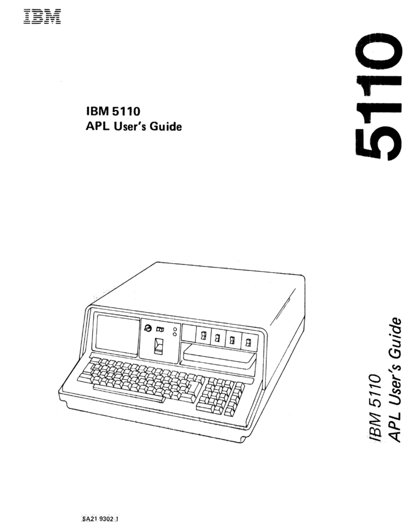
IBM System/370 145 Manual

GC38-0015-2
Systems

Systems
GC38-0015-2
Operator's Library:
IBM
System/370
Model
145
Operating Procedures

PREFACE
This reference manual
contains
information
necessary
to
operate
the
following units
of
the
IBM
System/370
Model
145.
•
-IBM
3145
Processing Unit
•
IBM
3210
Console Printer-Keyboard
•
IBM
3215
Console Printer-Keyboard
• Console File
Operating
information
for
related
software
and peripheral
devices
is
not
included.
The
reader
is
assumed
to
have:
1. Basic
computer
knowledge
and
experience,
or
2.
Operated
other
related
data
processing
equipment,
or
3. Previous
computer
operating
experience
on
a similar
system.
The
visual index, located
at
the
beginning
of
this manual,
is
an aid
for
quickly
locating
the
controls
and
indicators
described
in
this
publication.
IBM
is
grateful
to
the
American National
Standards
I
nstitute
(ANSI)
for
permission
to
reprint
its definitions
from
the
American National
Standard
Vocabulary for
Information
Processing (Copyright ©
1970
by American
National
Standards
Institute,
Incorporated),
which was
prepared by
Subcommittee
X3.5
Terminology
and
Glossary
of
American National
Standards
Committee
X3.
Third Edition (September 1972)
This
is
a major revision of, and obsoletes, GC38-001S-1 and
Technical Newsletter, GN24-0489, dated July 7, 1972.
Changes were made
in
the composition and format to im-
prove the readability and purpose
of
this publication. Before
us-
ing this manual, consult the latest SRL Newsletter for the editions
that
are applicable and current.
Requests for copies
of
IBM
publications should be made
to
your
IBM
representative or to the
IBM
branch office serving your
locality.
This manual has been prepared
by
the
IBM
Systems Development
Division, Product Publications, Dept.
KI0,
P.O. Box 6, Endicott,
N.Y. 13760. A form is provided at the back of' this publication
for readers' comments.
If
the form has been removed, comments
may be sent to the above address. Comments become the prop-
erty
of
IBM.
© Copyright International Business Machines Corporation 1971, 1972
This publication has five major sections:
•
System
Control Panel Indicators, Switches,
and
Keys
This section describes
the
purpose
of
individual indi-
cators, switches,
and
keys. It
does
not
describe
the
applications
of
these facilities within
operating
pro-
cedures.
• Console File
This section
contains
procedures
for
the
handling, in-
sertion,
and
removal
of
magnetic disk cartridges.
• Console Printer-Keyboard
This section
contains
PR-KB manual
operations,
initial
set-up
and
operator
adjustments,
maintenance
proced-
ures,
and
descriptions
of
indicators
and
controls.
• Operating Procedures
This section
contains
procedures
for
system
opera-
tion,
initialization,
and
error
recovery.
• Handling Abnormal
Situations
This section
contains
flowcharts
and
text
for
your
use
in analyzing unusual situations.
Associated publications are:
IBM
System/360
Disk Operating System Operator Communi-
cations and
Messages,
Order No. GC24-5074.
IBM
System/360
Operating System Messages and Codes,
GC28-6631.
IBM
System/370
Model 145 Functional Characteristics,
GA24-3557.
IBM System/360
and
System/370 Bibliography,
GA22-68~2.
OS/VS
Message
Library:
VS1
System
Messages,
GC38-1
001.

INTRODUCTION I
SYSTEM CONTROL PANEL INDICATORS, SWITCHES,
and
KEYS I
CONSOLE
FILE
I
CONSOLE
PRINTER-KEYBOARDS
I
OPERATING PROCEDURES I
HANDLING
ABNORMAL
SITUATIONS I
FEATURES I
GLOSSARY and
INDEX
I
3

VISUAL INDEX
Numbers
indicate the
pages
where descriptive text
is
found.
4
93
1"·'''''·'·''''1
I
"'~~."'.
I
0"""
,
..
.,
...
"
~.
I
l~nGIII"'flOSTO""GECOlll'ItO~
[±l
EBEJ
0:'
~~
D
...
D...
'0'
I
:;;-:
I
On
..
22
~~
8 8
14
22~
"
..
,",
0:;;::
68
8
..
·
..
"·
"'''
19
Ia
"
...
·,,·'"
:~~.,
...
"'
..
2
....
1
....
3."'1.,.)
•
'''(GIITIIII
"IlIG,ltlli
, DIIIGtSTU
IIICRIGISTU
Iij
""."''''''''
JOOCUM,,."UIITCIrtSL
!::':;';::~::;::'
13
.C
........
'JjTU
...
C.
1'14
...,.IIiIIOIIIO"
}
(lUI"
WORO
I
.C
....."WOIIIOC
~22
21
c=:J
~D
..
""'
..........
,,
,
~~
20@)@@@@@@@)20
F~~~~
I no"""".'0""" ,
ElB
EJ
B
00000
B
o 22
11
22

Introduction
. . . . . • . • . . • • . . 7
System Control Panel Indicators, Switches,
and
Keys.
. . . . 8
System Check Indicators
System Check Recovery
Power and Thermal Check Recovery
CPU
Status
Indicators .
Console-File
Indicators.
. . . . .
System Indicators . . . • • .
Display Assembler
Out
Roller Switch
A-Register Display Roller Switch
Toggle Switches . . . • .
Address Compare Switch .
Storage Select Switch
Rate Switch
Check Control Switch •
Diagnostic/Console-File Control Switch
Rotary Switches A Through H
Use
Meters.
• . . • . . .
Keys
........•.
Features (Indicators
and
Switches)
Console File
Cartridge Handling
Console Printer-Keyboards
· 8
· . 8
· 8
· 9
10
•
11
·
12
• •
13
• 14
15
· 16
·
17
· • 18
• . • • . 19
.20
· •
21
· . • . . 22
·
.24
.26
.27
.28
Printer Controls
(3210).
.
Carriage
Controls.
• . •
Keyboard . . • . .
. • • . . • 29
·
••••
30
Console
(3210
Model 1,
and
3215) .
3210
Model 2 Printer-Keyboard .
Ribbon Removal and
Replacement.
.
Forms Insertion . • . . . .
Platen Removal
and
Replacement • .
Print Element Removal
and
Replacement (3210) . . .
·
31
·
.32
· . . .
.33
·
.33
·
.37
• •
37
Print Element Cleaning (3210) . • • .
.38
.39
CONTENTS
Operating Procedures . . . . . . • • .
.40
Console-File Cartridge Insertion and Removal • •
Power·On Procedures • • . .
.40
.
41
.44
Initial Microprogram Load (IMPL) • . . .
IMPL Error Recovery • . . . .
-.
• .
Console Printer-Keyboard Manual Operations
Initial Program Load (IPL)
·
.47
.48
.55
IPL Error
Recovery.
. .
Set
IC
(Instruction Counter) .
....
55
Instruction
Step
. •
Clear Storage . . • . .
Data Compare
Trap.
. .
Manual Store/Display Operations
Power·Off Procedures . . . .
Emergency Pull
Switch.
• . .
.56
.57
.58
.59
• .
61
·
..
65
.68
Automatic
System
Checkout
Program (ASCP)
ASCP Operating Procedure . . • . • • •
System Error Record Editing Program (SEREP)
.69
·
.70
·
.79
Handling Abnormal
Situations
Introduction . . . . • • . • . .
Handling Abnormal Situations--Introductory
Flowchart.
.
..
•..•..•
Features.
. . . • . . .
Integrated File
Adapter
(I FA).
Emulators . . • • • • .
Channel-to-Channel
Adapter
(CTCA) •
Integrated Storage Control (lSC)
.83
.83
.84
·
.93
• • .
93
·
..
93
·
.93
· . .
93
Glossary. . . • . • . . . . . • . • • .
94
Index • . . . . . . . . • . . • . . .
95
5

ABBREVIATIONS
ADR
address
IPL
initial program load
ADDR
address
I/O
input
or
output
ASCP
automatic
system
checkout
program
MAN
manual
CF
console file
MS
main storage
CaRR
correction
as
operating
system
CPU
central processing
unit
PR-KB
printer
keyboard
CTCA
channel-to-channel
adapter
PSW
program
status
word
CU
control
unit
PWR
power
DIAGN
diagnostic
REG
register
DOS
disk
operating
system
REOD
required
EXE
execute
SDBO
storage
data
bus-out
IC
instruction
counter
SEREP
system
error
record editing program
IMPL
initial microprogram load
SYS
system
INTVN
REOD
intervention required
SYS
RES
system residence
INVlD
invalid
TOD
ClK time-of-day clock
6

I I I I
_-'
.,.,
.--
d-'
d--
10--
-
-
System/370
Model
145
Data Processing
System
This manual
contains
information
necessary
to
operate
the
System/370
Model
145
Processing
Unit
and
integrated
devices,
except
the
IFA. Order
numbers
for
manuals
containing
operating
procedures
for
individual
input/
output
devices can be
found
in
the
IBM
System/360
and
System/370
Bibliography,
GA22-6822.
Controls
and
indicators used
only
by
service personnel are covered
in
maintenance
documentation
for
the
system.
System/370
Model
145
performs
data
manipulations
and
input/output
operations
by
executing
microprogram
routines.
The
routines
executed
are
determined
by
the
machine
language
instruction
being processed.
The
Initial
Microprogram Load (IMPL) disk
contains
the
370
micro-
program
and
is
inserted
into
the
Console File (CF)
before
power
is
applied
to
the
system.
When
power
is
applied
to
the
system
and
the
370
micro-
program
is
loaded
into
control
storage,
the
system
is
ready
to
load
the
operating
system (OS, DOS, etc.)
or
a stand-
alone
program.
These_programs are loaded
by
using
the
INTRODUCTION
Initial Program Load (IPL)
procedure
in
this
manual.
Operating
procedures
necessary
before
a
problem
program can be run are:
1. Disk Cartridge Insertion (lMPL disk)
2. Power-on
3.
IMPL
(automatic
with
power-on)
4. IPL
the
operating
system (if required).
Whenever
power
has been removed
from
the
system,
these
four
procedures
must
be followed. When
power
is
dropped,
the
contents
of
control
storage
and
main
storage are invalid.
To
help us provide
you
with
better
documentation,
please use the Reader's
Comment
Form in the back
to evaluate this manual.
Introduction
7
I

SYSTEM
CONTROL
PANEL
INDICATORS,
SWITCHES,
and KEYS
SYSTEM CHECK
INDICATORS
e
STOR STOR
CLOCK
DIAGN
M REG BYTE CTRL STOR SEL
000000000000000000
II
PARITY
CHECK
======LI
SYSTEM
CHECKS
/I
~~~
II
CY~LE
~uAD~~~~ATE
:lI
000000080000000000
SYSTEM CHECK
RECOVERY
If a system check
is
indicated, re-IMPL and
then
re-IPL.
If
the
error
recurs, see
"Handling
Abnormal Situations--
Introductory
Flowchart,"
page
84.
POWER
and
THERMAL
CHECK RECOVERY
When a
power
supply failure
or
overtemperature
condition
occurs during a system
operation,
a power-off sequence oc-
curs.
The
POWER check indicator
on
alone indicates a
8
power
supply failure.
The
THERM indicator on along
with
the
POWER check indicator indicates an overtem-
perature
condition.
1. Press CHECK RESET key (resets
the
indication and
allows
the
POWER
ON
key
to
be operative).
2. Press POWE R
ON
key.
If
the
condition
causing
the
failure was
temporary,
power
will
come
up
normally. If
power
cannot
be restored, see
"Handling
Abnormal Situations--Introductory
Flowchart,"
page
84.

CPU
STATUS INDICATORS
8
BIeE!
Service
Use
Indicators
not
described
in
the
chart
are for
service personnel and are described
in
mainte-
nance documentation.
~(9)@@@@~@
~
B
EJG
CPU
STATUS
ADR
SNG
ADR TOO
CF
EXE CaMP CLOCK STaR TRAP TRAP
ECC
EC
CS
X.LATE
CLOCK LOG
SNG
PWR
IMPL
000066660000000008
n CYCLE n
INDICATOR
CONDITION
INDICATED
CPU
stopped
state
reached as a resu It
of:
1. Pressing
the
STOP
key.
EXE CPLT
2.
The
RATE switch being in
the
INSTRUCTION
STEP
position.
3. A
match
being
detected
while in
the
address
match
mode
of
operation.
The
address
(real
or
logical) being used
to
access main
storage
matches
the
address
set
into
switches
CDE FGH
during
an
ad-
ADR COMP MATCH dress
match
operation.
The
action
taken
by
the
CPU as a
result
of
the
match
condition
is
controlled
by
the
setting
of
the
ADDRESS
COMPARE
CONTROL
switch.
CLOCK
STOP
CPU is
in
a
hard-stop
condition
(CPU clock
not
running).
TOO
CLOCK INVLD
Time-of-day
clock
is
invalid.
The
indicator
is
turned
off
by
successfully
executing
a
set
clock
instruction.
A log
is
present
in
the
log
area
of
main storage. When
the
LOG PRES
CHECK
CONTROL
switch
is
in
the
STOP
AFTER
LOG
position
and
the
LOG
PRES
indicator
is
on,
SEREP
may
be
run.
SNG ECC
One
of
the
data
or
check
bits
from
storage
has
been
corrected.
CF PWR
ON
Power
is
applied
to
the
console
file.
IMPL
REaD
An IMPL
operation
is
required.
(See page 44)
System
Control
Panel
Indicators,
Switches,
and
Keys 9
I

CONSOLE-FILE INDICATORS
[===:J
c:::g
0=
~
8
'.
.
...
-
":.,
."
....
'
B
§]
~i
.
··<;,*f::.:~
..
;ffi.
=
2i~.
@)125@@@@@@)
"/00
'
..............•.......
~~
.BS
<"9>8';
.
EJG'
'8
M~~1:l
G
CONSOLE
FILE
CONSOLE
FILE
REGISTERS
DISK
CPU
0000080058666616666
Operator
Use
CONSOLE
FI
LE
CHECKS
Re-IMPL when any console-file check indicator
is
on.
If
the error recurs see "Handling Abnormal Situations--
Introductory Flowchart,
1/
page
84
Service Use
CNTR MATCH and CONSOLE
FI
LE
REGISTERS
These indicators are used by service personnel, and
described
in
maintenance documentation.
10

SYSTEM INDICATORS
~
D
••
~~
D~
D_
B
§~
~D
c::::J
D~
C!JD
0
BEl
INDICATOR
SYS
MAN
WAIT
TEST
LOAD
e
<!>l;S~O~~~OOO~O
SOO~e"&o~
[email protected]!OMWlM
~~~ii*oo80666~
~
00000
CONDITION
INDICATED
CPU
operations
are
in
progress
and
either
use
meter
is
running.
CPU
clock
is
stopped
or
the
system
is
in a
soft-stop
state.
All
pending
interrupts
are
handled.
Manual
store/display
operations
are
possible
only
when
the
MAN
indicator
is
on.
System
is in a
wait
state
(CPU
clock
running
but
no
instruction
processing
taking
place).
If
an
interrupt
occurs,
the
CPU is
taken
out
of
wait
state
and
processing is
started
under
control
of
the
program
being
executed.
Any
of
the
following
switches
are
not
in
the
PROCESS
or
NORMAL
position.
1.
RATE
2.
CHECK
CONTROL
3.
DIAGNOSTIC/CONSOLE
FI
LE
CONTROL
4.
ADDRESS
COMPARE
CONTROL
Initial
Program
Load
(lPU
is in process.
This
indicator
turns
on
when
LOAD
is
pressed
and
turns
off
when
the
initial PSW
is
loaded
successfully.
System
Control
Panel
Indicators,
Switches,
and
Keys 11
I

DISPLAY ASSEMBLER OUT ROLLER SWITCH
e
~~~O~O~~~~OGO~O
~~oo~o~~~oooooo~~
~e~~6~~~~~~501$
~~~~i*o080666~666
The DPLY ASMBLR OUT roller switch provides a continuous
display
of
the following:
INFORMATION DISPLAYED
POSITION I I
Byte 0 Byte 1 Byte 2 T
1 M-Register Bytes
1,2,
and 3 (Notes 1 and
2)
2 Storage Data Bus-Out
3* C-Register
4*
MB-2
r
MB-3
I
N2
I
5*
B-Register
6* Z-Register
7*
D-Register
8*
MCKA
Notes:
1. Storage
protect
stack key
is
displayed
in
bits 0-3
of
byte
O.
2.
Bits 0-3
of
byte
1 displays
the
selected channel.
*Positions 3
through
8 are for service personnel.
12
Byte
3
N3

A-REGISTER DISPLAY ROLLER SWITCH
The A-REGISTER DISPLAY roller switch
is
used
with the
STORAGE SELECT switch
to
display the following.
INFORMATION DISPLAYED
POSITION
Byte
0 Byte 1
Byte
2
e
1 Storage
or
External Register (Notes 1
and
2)
2* TI-Register TA-Register TT-Register
3*
S-Register P-Register T-Register
4*
System
Register Bytes 0, 1, and 2
Byte
3
TE-Register
L-Regi.ster
H-Register
5*
MPX
Channel Registers
or
Selector Channel External Word GTAG (IFA: FTAG)
6* Channel Word A (External Word GSTAT) (lFA: FSTAT)
7*
Channel Word B (External Word GBS) (IFA: FCND)
8*
Channel Word C (External Word GBUF) (IFA: FBAK)
Notes:
1. Position 1
is
described in
the
"Manual
Store/Display
Operations,"
page 61.
2. When
the
CPU is in soft-stop
state
(MAN indicator on),
the
indicators display
the
next
instruction
address.
* Positions 2
through
8 are for service personnel.
A REGISTER DISPLAV
1 STORAGE/EXT
REGS
2 DOCUMENTARY CNSL
3
S,P,
T,
LREGISTERS
4 SYSTEM REGISTER
5 CHAN INTERFACE
6
CHANWORDA
1 CHAN WORD B
8 CHAN WORD C
System
Control Panel Indicators,
Switches,
and
Keys
13
I

TOGGLE SWITCHES
~
~
OFF
D
rESr
lamp
Test
SHIfT
O
~~s~
AUA
CM~D
HARD
O
STOP
SYNCI
NORM
STOP
OI~1(
AOA
o
~~~~
NORMAL
oOISABLE
All system
control-panel
and
PR-KB indicators should light
when
the
LAMP
TEST
toggle switch
is
in
the
TEST
position.
This switch can be
operated
at
any
time
without
affecting
system
operation.
Interval Timer
NORMAL
This position allows a value
to
be set into
or
read
out
of
the
interval
timer
location,
main storage location
80
(hex
50).
DISABLE
This position disables
the'
inte:-val timer.
The
content
of
the
timer
is
not
available
to
the
data
flow
for
timer func-
tions. Display
of
timer
location
80
(hex 50) in
this
posi-
tion
shows
the
last value
stored
into
storage location
80
(hex
50).
This value could be
the
initial
timer
setting
or
other
program information.
Time-of-Day Clock(TOO
ClK)
ENABLE
SET
This
position enables
the
set
clock instruction
to
change
the
value
of
clock.
SECURE
This
position allows executing
the
set
clock instruction
without
affecting
the
clock value.
14
e
~l!5~o~o~~~~~ooo~o
eMoo~o~~~OOOOOOl!5<:l"
~~~~~~~6~~5~&£
~~~0i§o050666~666
Address Compare
Control
This switch is used with
the
ADDRESS COMPARE
and
the
STORAGE SELECT
rotary
switches
to
determine
the
action
taken by
the
CPU-as a result
of
an address
compare
match.
The
CPU
should
be
in
manual
state
(MAN
indicator
on) before using
this
switch. (Example: Press STOP key.)
SYNC/NORM
This position
is
the
normal
operating
position. This
position also provides a
sync
pulse
for
service use,
and
does
not
result
in
a
stopon
an address
match.
STOP
This position provides a soft-stop whenever an address
match
is
detected.
To
restart
the
CPU, press
the
START
key. With
the
switch in
this
position,
the
TEST
indicator
is
on.
HARD STOP
This position
is
for
service personnel and is described
in
maintenance
documentation.
With
the
switch
in
this
position,
the
TEST
indicator
is on.
Console-File Register Display
These switches are used
by
service personnel and are des·
cribed
in
maintenance
documentation.

ADDRESS COMPARE SWITCH
•
This
switch provides a
match
when
the
address
used
to
access main storage
matches
the
address
set
in
rotary
switches
CDEFGH,
and
the
STORAGE
SELECT
switch
is
set
to
the
MAIN
STORAGE
position
.
•
The
action
taken
by
the
CPU
as
a
result
of
the
match
condition
is
determined
by
the
ADDRESS
COMPARE
CONTROL
toggle switch.
C=-==:J
Gg
0:,
Q.
8
~0~o30~~~~~OOO~O
~~oo6o~~~oooooo~~
~~~~O~~506~
~~~~00506666P666
B
BG
B
50000
G
ADDRE~::MPARE
~
Operator
Use
ANY
(REAL
ADR)
This
position
is
for
normal
program
processing. With
the,
switch
in
this
position,
a
match
occurs
for
main storage
access
when
the
storage
address
matches
the
address
set
in
rotary
switches
CDEFGH.
Note:
To
guarantee
a
match
on
instruction
addresses,
the
I-COUNTER
positions
must
be used.
DATA
STOR
This
position
allows a
match
when
the
storage
address
matches
the
address
set
in
rotary
switches
CDEFGH
during a
data
store
operation.
I/O
(Input/Output)
This
position
allows a
match
when
the
storage
address
matches
the
address
set
in
rotary
switches
CDEFGH,
and
the
operation
is
storing
or
fetching
data
for
an
I/O
operation.
I-COUNTER
(REAL
or
LOGICAL
ADR)
These
positions
allow a
match
when
the
real
or
logical main
storage
address
matches
the
address
in
rotary
switches
CDEFGH,
and
the
operation
is
an
instruction
fetch
from
main storage.
I
Note:
Significant
throughput
degradation
can
occur
while
processing
with
this
switch
set
to
the
I-COUNTER
REAL
ADR
position,
and
the
ADDRESS
COMPARE
CONTROL
switch
in
the
STOP
or
HARD STOP
position.
DATA COMPARE
TRAP
This
position
determines
which
instruction
is
causing a par-
ticular
storage
byte
location
to
be
modified.
See
"Data
Compare
Trap,"
page
59.
ANY
(LOGICAL
ADR)
This
position
allows a
match
when
the
logical main
storage
address used
to
access storage
matches
the
address
set
in
rotary
switches
CDEFGH.
Note:
To
guarantee
a
match
on
instruction
addresses,
the
I-COUNTER
positions
must
be used.
Service Use
The
switch
positions
not
defined
are
for
service
personnel
and
are
described
in
maintenance
documentation.
System
Control
Panel Indicators,
Switches,
and
Keys
15

STORAGE SELECT SWITCH
• This switch selects
the
proper
storage
for
manual
store/
display operations.
It
is
also used with ADDRESS
COMPARE and ADDRESS COMPARE CONTROL
switches for address match functions.
•
Store
and display functions should be initiated from
the
PR-KB because
that
facility
cannot
cause con-
current
I/O operations
to
overrun.
The
manual store
and display functions should be used only when no
I/O operation
is
in
process
or
when loss of I/O infor-
mation
is
unimportant.
e
~0~O~O~~a~000~O
~~o~o~~~~
~~~~~50~g~~~S3 ~~~~S§oo56666~
MAIN
STORAGE
II
MPX
CH@ACONTROLSTORAGE
1/
CHAN
1
O.
~~g~~GE
OR
~~1
CHAN
2 •
EXP
LOCAL
II
STOR
REGS
CHAN
3.
•
1=:=====
CIlAN 4
16
Operator
Use
MAIN STORAGE
This position is
for
normal program processing
and
for
manual
store
and display operations
of
main storage.
LOCAL STORAGE
This position
is
for manual store and display
of
general
and
floating-point registers.
Service Use
The switch positions
not
defined are
for
service personnel
and
are
described
in
maintenance
documentation.

RATE SWITCH
• This switch controls
the
rate
at
which
the
CPU
processes instructions.
• This switch,
in
any position
other
than PROCESS,
turns
on
the
TEST indicator.
o;:J
~~
D..
D~
0_
B
§]~
!2lD
C::=J
D~
C!JD
o
EJE]
e
~~~o~i&a~ooo~o
-SM~OS"~&OOOOOM
M~2k~MMmM
~O&li*oo50666~
PROCESS
STEP
(¢JARDSTOP
O .
CONSOLE
FILE
BYTE
COUNT
HARD
STOP
Operator Use
PROCESS
This position
is
for normal program processing.
INSTRUCTION STEP
In
this position, one complete machine language
instruction (including
all
pending interrupts allowed by
the
system mask)
is
executed for each operation
of
the
START key.
The
machine enters
the
soft-stop state, and
the
EXE
CPLT indicator
turns
on.
The
address
of
the
next
instruction
is
displayed
in
the
A-REGISTER DISPLAY
roller switch, position 1.
Service Use
The
switch positions
not
defined are for service personnel
and are described in maintenance documentation.
System Control Panel Indicators, Switches, and Keys 17
I

CHECK CONTROL SWITCH
• This switch controls
the
action taken by
the
CPU when
a machine check occurs.
• This switch,
in
any
position
other
than PROCESS,
turns
on
the
TEST indicator.
18
E'=:J
Q;J
0:.
Q.
B
[§]~
EJO
c::::J
O§J
00
o
BEl
8
~0~O~O~00~~~~OOO~O
~~~oo~o6~~oooooo~~
~8~Q§9_6~e~6b~6o~~
~~0000080666~666
CHECK CONTROL
Operator Use
PROCESS
This position
is
for
normal program processing when an
operating system with
automatic
recording
of
logout
data
is
used.
STOP AFTER LOG
This position
is
for
normal program processing
when
an
operating system
without
automatic
recording
of
logout
data
is
used.
With
the
switch
in
this position, a diagnostic logout into
main storage (locations
128
through 704)
stops
processing
and
turns
on
the
LOG PRES and RETRY indicators.
The
diagnostic logout can
contain
information
about
a machine
check, channel
control
check,
or
an interface control check.
After
a diagnostic logout, you
may
run
the
System Error
Record Editing Program(SEREP).
Note: Programs using storage locations
128
through
704
are
invalid
after
a diagnostic logout into main storage.
To
con-
tinue
processing,You
must
re-IPL.
Service Use
The
switch positions
not
defined are
for
service personnel
and are described in maintenance
documentation.

DIAGNOSTIC/CONSOLE-FILE CONTROL SWITCH
•
The
DIAGNOSTIC/CONSOLE
FI
LE
CONTROL switch
controls
console-fi,le and diagnostic
functions
.
• This switch, in any position
other
than
PROCESS/IMPL,
turns
on
the
TEST indicator.
rn
[Eo~
~o=_
0::
_
B
§]~
~O
c.=J
O§J
00
o
BEl
8
~~~O~O~~~000~O
~i3oo6o~~~OOOOOO~0
~~~~6~~~6~~~~~
~~0~oo50666op666
DIAGNOSTIC/CONSOLE FILE CONTROL
PROCESS/IMPL
STORAGE
IL-
k~~~-H
.RECYCLE
C~~~~LE
II
SC©©_.
READ
II
'X'CTRLWORD.
0 .
CEMOD',Jj
SWSA-H
Operator Use , I
PROCESS/IMPL
This position
is
for
normal program processing and
for
loading
from
the
console file.
Service Use
The
switch positions
not
defined are
for
service personnel and
are described in maintenance
documentation.
System Control Panel Indicators, Switches, and Keys 19
Other manuals for System/370 145
3
Table of contents
Other IBM Desktop manuals

IBM
IBM 360 User manual

IBM
IBM 3278 Use and care manual

IBM
IBM PS/2 95 XP 486 Owner's manual

IBM
IBM NetVista 6029 User manual

IBM
IBM Aptiva 2170 Owner's manual

IBM
IBM NetVista A20 Instructions for use

IBM
IBM System/32 Reference manual

IBM
IBM Personal System/2 50 Use and care manual

IBM
IBM Aptiva User manual

IBM
IBM NetVista A30 User manual