IBM 2250 3 User manual

---
-
----
- -
---
-
---
=-
-:§~§:
Systems Reference Library
IBM
System/360
Component Description
IBM
2250
Display Unit Model 3
IBM
2840
Display Control Model 2
This
document
presents
detailed
information
about
IBM 2250
Display
Unit
Model
3/IBM
2840
Display
Control
Model
2
pro-
gramming,
operation,
and
special
features.
The
material
is
presented
with
the
assumption
that
the
reader
has
read
the
IBM
System/360
Principles
of
Operation
manual,
Form
GA22-6821.
The
following
publications
may
also
be
of
interest
to
the
reader:
• IBM
System/360
Component
Description:
IBM 2250
Display
Unit
Model
1,
Form
GA27-2701.
• IBM
System/360
Operating
System,
Graphic
Programming
Services
for
IBM 2250
Display
Unit,
Form
GC27-6909,
File
No.
8360-03
Form
GA27-2721-1

Second
Edition
(March,
1971)
This
edition,
Form
GA27-2721-1,
incorporates
information
contained
in
Technical
Newsletter
N27-2934
pertaining
to
the
Display
Copier
attachment.
This
edition
obsoletes
Form
GA27-2721-0
and
Technical
Newsletter
N27-2934.
Changes
are
indicated
by
a
vertical
line
to
the
left
of
the
change.
Copies
of
this
and
other
IBM
Publications
can
be
obtained
through
IBM
Branch
Offices.
Address
comments
concerning
the
contents
of
this
publication
to:
IBM
Corporation,
Product
Publications,
Dept.
528,
Kingston,
New
York 12401
©
International
Business
Machines
Corporation
1967, 1971

INTRODUCTION •
2250
OPERATIONS
General
Displays
Vectors
and
Points .
Characters
Light
Pen.
Alphameric
Keyboard.
Programmed
Function
Keyboard
2840
OPERATIONS WITH ATTACHED
2250's
Orders
Order
Fonnat
Graphic
Mode
Orders .
Character
Mode
Orders
Control
Mode
Orders .
Light
Pen
Mode
Orders
Display
Regeneration
.
Display
Regeneration
Timing
2840
OPERATIONS
WITH
THE CHANNEL
Interface
Operations
.
Commands
.
Write
Buffer
Command
Read
Commands
.
Figure
1
Attachment
of
2840-2/2250-3
Configuration
to
System/
360
•
Figure
2
Example
of
a
2250
Display
•
Figure
3
Functional
Sections
of
a
2250-3
Figure
4
Display
Area
Coordinate
Addressing
System.
Figure
5
Examples
of
Display
Area
Coordinate
Address
Modification
by
the
2250
.
Figure
6
Character
Set
and
Code
Assignments
.
Figure
7
Character
Grid
Coordinate
System
Figure
8
Strokes
that
Fenn
the
Letter
"A"
Figure
9
Character
and
Line
Spaces
Figure
10
Fiber
Optic
Light
Pen
.
Figure
11
Alphameric
Keyboard.
Figure
12
Programmed
Function
Keyboard
Table
1
Character
Display
Characteristics
•
Table
2
Mode
Orders.
Table
3
Displayable
Vectors
Per
2250-3
at
a
Regener-
ation
Rate
of
40
cps
Table
4
Displayable
Vectors
Per
2250-3
at
a
Regen-
eration
Rate
of
30 cps
Table
5
Displayable
Characters
Per
2250-3
at
a
Regeneration
Rate
of
4-0
cps
5
7
7
8
9
10
12
12
15
17
17
17
17
20
21
23
25
26
31
31
32
33
34
5
7
8
9
9
11
12
13
13
14
14
16
11
19
28
29
30
CONTENTS
Control
Commands
Sense
Command
36
38
Instructions
• 39
Test
I/O
•
39
Halt
I/O
.
39
Examples
of 284-0/2250
Operations
39
Example
1.
Displaying
an
Image
on
One
2250
39
Example
2.
Nonnal
Light
Pen
Operation
-
2250
Equipped
with
Programmed
Function
Keyboard
. 41
Example
3.
Alphameric
Keyboard
Operation
42
Graphic
Design
Operations
42
Entities
•
42
Buffer Subroutines
43
Input
by
Light
Pen
Search
43
Input
by
Light
Pen
Tracking.
43
Feedback
by
Light
Pen
Tracking
History.
43
CONTROLS AND INDICATORS. 53
Basic
Operator
Controls
and
Indicators
53
Metering
.
54
APPENDIX A: HEXADECIMAL -DECIMAL CONVERSION
56
APPENDIX
B:
STATUS-SENSE COMBINATIONS 61
GLOSSARY
INDEX
Figure
13
Figure
14
Figure
15
Figure
16
Figure
17
Figure
18
Figure
19
Figure
20
Figure
21
Figure
22
Table
6
Table
7
Table
8
Table
9
Table
10
Table
11
Table
12
64
65
ILLUSTRATIONS
Functional
Sections
of
the
2840-2
and
a
2250-3
18
Read
Manual
Input
Command
Response . 35
Programmed
Function
Keyboard
Overlay
(Top
View)
36
Buffer
Program
Example
Display
40
Sequence
of
Routines
in
Light
Pen
Tracking
History
Programming
Example
•
47
Flow
Diagram
of
Example
Program
49
Point
Pattern
Used
in
Example
Program
51
Vector
Pattern
Used
in
Example
Program
52
2250-3
Operator
Controls
and
Indicators
.
53
2840-2
Operator
Panel
54
TABLES
Displayable
Characters
Per
2250-3
at
a
Regen-
eration
Rate
of
30
cps
30
Status
Byte Bit
Assignments
• 32
Commands
Used
with
the
284-0-2 33
Sense Bit
Assignments
38
Buffer
Program
Example
41
Sample
Entity
Routine
42
Feedback
by
Light
Pen
Tracking
History,
Example
Routine
44

IBM
2840 Display Control, Model 2

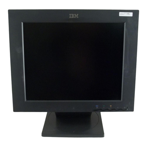
The
IBM 2250
Display
Unit Model 3
(Frontispiece)
is
a
cathode-ray-tube
(CRT)
display
console
which
can
be
attached
to
a
System/360
via
the
IBM 2840
Display
Control
Model
2.
Along
with
the
capability
of
displaying
graphic
or
alphanumeric
information,
the
2250
offers
man-machine
interaction
through
its
light
pen
and
two
keyboards.
Using
these
facilities,
a
programmer
can
furnish
computer-aided
design
capabilities
whereby
the
2250
user
can
create,
modify,
and
add
graphic
and
alphanumeric
data
into
the
system
through
the
display
screen.
This
exten-
sion
of
the
System/360
data
processing
power
is
useful
(1)
for
handling
the
graphic
information
asso-
ciated
with
scientific
and
engineering
applications,
and
(2)
for
providing
faster
and
more
effective
retrieval
and
graphic
expression
of
management
and
business
operating
data.
Programming
requirements
for
the
2250
differ
from
other
I/O
devices
in
that
the
2840
Display
Control
has
a
buffer
with
logical
capabilities
that
require
programming.
A
buffer
program
consisting
of
buffer
orders
and
data
to
be
displayed
can
be
developed
either
in
final
image
form
or
as
a
frame-
work
to
accept
data
(to
be
provided
at
object
time)
by
the
CPU
program
and
to
be
transmitted
via
a
channel
to
the
2840-2.
Under
control
of
this
buffer
program,
the
2250-3
displays
graphic
images
in
the
form
of
lines,
points
,
and
alphameric
characters.
Using
the
logical
capabilities
of
the
buffer
and
the
light
pen,
programmed
function
keyboard,
and
alphameric
keyboard,
the
programmer
can
design
and
implement
his
own
tracking,
sketching,
or
dis-
play
manipulation
techniques
with
minimum
CPU
interaction.
A
buffer
program
consists
of
orders
interleaved
with
data.
The
three
major
groups
of
orders
are
Graphic,
Character,
and
Control.
When
decoded,
an
order
sets
a
mode
of
operation
which
will
be
in
effect
until
another
order
is
encountered.
All
data
in
between
is
processed
in
that
mode.
Hence,
an
order
requesting
absolute
vectors
will
put
the
2250/2840
in
Absolute
Vector
mode,
and
all
following
data
will
be
treated
as
the
absolute
X,
Y
end
points
of
vectors
to
be
displayed
until
the
next
order
is
en-
countered.
Available
in
conjunction
with
this
basic
principle
is
the
ability
to
control
light-pen
responses
in
the
2840/2250.
These
orders
can
condition
the
2840/2250
to
accept
light-pen
detects
until
another
light-pen
order
resets
the
condition.
A
light-pen
detect
on
any
displayed
information
between
these
two
orders
is
then
accepted
and
passed
on
to
the
program
for
processing.
In
addition,
immediate
action
orders
allow
direct
transferring,
movement
of
INTRODUCTION
data
and/or
addresses,
and
storage
of
the
deflection
registers
into
a
buffer
location.
Each
2250-3
can
operate
up
to
2,000
ft.
from
the
2840-2,
allowing
access
to
the
computer
from
the
user's
normal
working
area.
Furthermore,
sharing
of
the
common
control
unit
(the 2840-2)
by
several
2250-31s
results
in
more
economical
configurations
for
the
multiconsole
environment.
The
2840-2
can
control
the
operation
of
up
to
four
2250-3
Display
Units
(Figure
1).
Light-pen
tracking
can
be
performed
simultaneously
by
the
user
of
each
2250
with
no
interference
to
System/360.
Attachment
of
the
2840-2
to
System/360
(CPU)
and
CPU
main
storage
is
via
either
a
selector
or
multiplexor
chan-
nel;
it
uses
one
of
the
eight
control
unit
positions
on
the
channel
interface.
The
channel
provides
the
2840-2
with
the
data
to
be
displayed
and
with
the
control
information
necessary
to
direct
the
operation
of
the
2840-2
and
associated
display
units.
Buffer
storage
in
the
2840
stores
digitally
coded
images
for
each
attached
2250-3.
The
buffer
enables
image
regeneration
as
well
as
message
composition
from
the
2250
alphameric
keyboards;
this
allows
the
2840-2
and
attached
2250-3's
to
operate
concurrently
with
the
computer
system,
freeing
the
CPU
and
the
channel
for
other
functions.
Buffer
storage
areas
are
program-assignable
for
any
attached
2250-3
and
can
be
varied
under
program
control.
The
2840-2
controls
the
operation
of
each
attached
2250-3.
By
means
of
shared
circuitry
and
interleaved
operations
in
the
2840-2,
each
2250-3
can
be
operated
independ-
ently,
and
different
images
can
be
generated
simul
-
taneously
on
each
display.
The
basic
2250-3
(without
special
features)
pro-
vides
the
ability
to
display
graphic
information
in
System/.360
r----
2250
Model 3
One 2840
can
control
up to
four
2250 Model 3
Display
Units
2250
Model 3
Up
to 2000 feet
IJp
to 2000 feet
;
Selector
or
Up
to
7
I Multiplexor !--------------(additional
I Channel control units
Figure
1.
Attachment
of
2840-2/2250-3
Configuration
to
System/360
Introduction
5

absolute
or
incremental
mode
in
the
form
of
points
or
straight
lines
in
any
direction;
it
can
also
display
alphameric
characters
(alphabetics,
numerics,
and
special
symbols).
In
addition,
a
light
pen
is
provided
with
the
basic
2250-3.
For
increased
intercommu-
nication
between
the
user
and
the
controlling
program,
two
keyboards
are
available
as
special
features:
Alphameric
Keyboard
-
Provides
a
typewriter-like
keyboard
with
which
the
user
can
perform
editing
functions
and
compose
messages
consisting
of
letters,
numbers,
and/
or
special
symbols
for
entry
into
2840
buffer
and
CPU
main
storage.
Programmed
Function
Keyboard
-
Provides
com-
munication
between
the
user
and
the
computer.
The
keyboard
consists
of
keys,
indicators,
and
sensing
switches
for
use
with
replaceable
descriptive
over-
lays.
The
function
of
each
key
and
indicator,
which
is
program-defined,
is
identified
to
the
program
by
the
overlay
coding
and
to
the
user
by
symbols
on
the
overlay.
The
program
associated
with
the
overlay
code
and
the
selected
key
then
directs
the
requested
operation.
For
example,
as
a
result
of
a
key
de-
pression,
the
program
might
direct
the
computer
to
enlarge,
reduce,
or
delete
the
image
displayed
by
the
associated
2250.
When a 2250
is
not
in
the
same
room
with
the
2840
and
the
CPU,
a
telephone
should
be
near
the
2250
so
that
the
2250
operator
can
communicate
with
the
CPU
installation.
The
basic
2840-2
contains
a
32,
768-byte
core
buffer,
order
mode
control,
and
a
character
gener-
ator.
The
character
generator
can
translate
one
System/360
eight-bit
byte
representation
from
an
6
alphameric
character
into
a
sequence
of
signals
which, when
converted
to
analog
deflection
signals
by
the
2250-3,
cause
the
character
to
be
drawn
on
the
2250-3
CRT
display
area.
A
standard
character
set
of
63
alphabetics,
numerics,
and
special
symbols
is
provided;
two
character
sizes
are
program-
selectable.
The
basic
2840-2
can
attach
to,
and
con-
1
trol,
two
2250-3's.
A
special
feature,
Display
Multiplexer,
is
available
for
increased
2840-2
attachment
capability:
Display
Multiplexer
-Allows
attachment
of
two
additional
2250 Model 3
Display
Units
to
the
2840-2.
A
maximum
of
one
display
multiplexer
feature
can
be
installed
on
one
2840-2,
allowing
attachment
of
up
to
four
2250-3's.
Display
Copier
Attachment
-
Permits
attachment
of
an IBM 2285
Display
Copier
to the 2250.
The
publication
Component
Description,
IBM 2285
Display
Copier,
Form
GA27-2730,
contains
a
functional
description
of,
and
operator
procedures
for,
the 2285.
The
2285
is
a
free-standing,
non-
programmed
device;
it
provides,
under
2250
operator
control,
8-1/2
by
11-inch
paper
copies
of
the
2250
display
image.
Each
copy
consists
of
a
black
image
on
a
light
gray
background.
The
2285
is
located
beside
the
left
edge
of
the
2250
reading
board;
in
this
position,
the
2285
controls,
indicators,
and
hopper
(copy
receptacle)
are
easily
accessible
to
the
2250
operator.
Basic
power
for
the
2285
is
provided
by
the
2250. Analog
signals
are
switched
from
the
2250 to the 2285
during
the
paper-exposure
portion
of
each
copy
cycle.

GENERAL
Each
2250-3,
under
control
of
a
2840-2,
generates
images
on
the
12-inch
by
12-inch
usable
display
area
of
a
21-inch
cathode-ray
tube
(CRT).
An
image
can
be
composed
of
straight
lines
(vectors)
,
points,
standard
characters
(in two
sizes),
and
special
char-
acters
formed
with
vectors
and
points
(Figure
2).
A
visible
display
is
produced
when
an
el
ectron
beam
in
the
CRT
strikes
the
phosphor-coated
CRT
screen,
causing
the
portion
of
the
coating
struck
by
the
beam
to
glow
briefly.
Normally,
the
glow
fades
within
a
fraction
of
a
second,
too
soon
for
the
human
eye
to
carefully
perceive
and
identify
the
image.
For
this
reason,
the
display
must
be
redrawn
continuously
Figure
2.
Example
of
a
2250
Display
2250
OPERATIONS
(regenerated)
at
a
rate
that
will
cause
the
display
to
appear
steady
and
stationary
to
the
observer.
Re-
generation
is
performed
automatically,
under
control
of
a
program
in
the
2840.
The
2840
accomplishes
regeneration
by
continuously
retransmitting
control
and
display
data
to
the
2250;
this
data
can
be
modified
during
regeneration
by
the
2840,
as
directed
by
the
buffer
program
and/or
the
CPU
program,
to
update
or
change
the
display.
The
2250
also
performs
various
nondisplay
services
for
the
user
by
providing
the
interface
between
the
user
and
the
problem
pro-
gram
with
the
following
devices:
1.
Programmed
function
keyboard
.
Provides
keys
and
overlays
for
user
communication
2250
Operations
7

to
the
program
and
indicators
for
program
communication
to
the
user.
2.
Alphameric
keyboard.
Enables
the
user
to
change,
edit,
or
create
character
displays.
3.
Light
pen.
Supplies
the
buffer
address
of
a
vector,
point,
or
character
at
which
the
user
is
pointing
a
pen-like
device.
This
information
can
be
used
for
operations
as
determined
by
the
program,
by
the
alpha-
meric
keyboard,
or
by
the
programmed
function
keyboard.
The
light
pen
thus
enables
the
user
to
enter
and
manipulate
graphic
information.
4.
Audible
alarm
(single-stroke
buzzer).
Enables
the
program
to
inform
the
operator
that
action
is
required.
2840
Via
Interface
Control to Channel 2840
Buffer 2840 Line Buffer
Reg
,------A---,
'
Indicator
Data
Stroke Codes
Character
Stroke
Deflection
Character
and
Cursor Keys
END and
CANCEL Keys
Audible
Alarm
Notes:
key,
overlay
codes
r
---
,
I
Programmed I
I Function I
: Keyboard I
L
_____
.J
1. Dashed blocks represent
special
feature
functions.
2.
Heavy lines
represent
data
flow.
r
---
1
: Alphameric I
I Keyboard I
L---
__
J
Figure
3,
Functional
Sections
of
a
2250-3
8
Intensity
The
functional
sections
of
the
2250
are
shown
in
Figure
3.
The
functions
represented
by
solid
blocks
are
provided
in
the
basic
units,
whereas
those
re-
presented
by
dashed
blocks
are
available
as
special
features.
Heavy
connecting
lines
represent
data
flow;
the
light
lines
represent
control
signal
routing.
DISPLAYS
Information
positioning
on
the
2250
display
area
is
controlled
by
a
display
program
resident
in
the
2840
buffer.
This
buffer
program
is
prepared
by
the
main
CPU
and
is
sent
to
the
buffer
via
a
standard
I/O
channel
operation.
The
program
specifies
electron
beam
deflection
to
horizontal
(X)
and
vertical
(Y)
coordinates
on
a
virtual
square
grid
composed
of
Coordinate
Data
Beam Bits
Main
Deflection
Assembly
Control
Various I
~---'
X-Y
Coordinates
Operator
Panel
2840 Control
,----A---,
•
Light Pen
Detect
light
Pen

possible
electron-beam~deflection
end
points.
This
grid
covers
(logically)
the
12-inch
by
12-inch
display
area
on
the
face
of
the
CRT;
it
comprises
1,
024
equally
spaced
X
positions
and
1,
024
equally
spaced
Y
positions
(Figure
4).
Positioning
data
in
the
display
program
selects
the
X
and
Y
coordinates
for
each
element
of a 2250
display
(each
point,
line
end
point,
and
character
area
centroid).
This
same
data
can
also
control
the
IBM 2280
Film
Recorder.
The
grid
of
addressable
coordinates
for
a 2250
or
2280
device
is
called
its
"raster".
The
space
between
two
sequentially
ad-
dressable
lines
on
the
raster
is
called
a
raster
unit.
A 2250
raster
unit
represents
1/1,
023
of
the
image,
whereas
a 2280
raster
unit
represents
1/4,095
of
the
same
image;
this
reflects
the
difference
in
address
resolution.
The
data
format
in
the
2840
provides
for
the
4,
096-by-4,
096-position
grid
of
the
2280
and
2282
film
units.
The
2250
maintains
program
compati-
bility
with
the
film
units
by
disregarding
the
two
low-order
bits
(binary) of
the
4,096-by-4,096
X and
Y
coordinates.
For
example,
a
binary
configuration
1111 1111 1111 (4, 095
decimal)
in
the
2840
is
inter-
preted
by
the
2250
as
1111111111,
or
1,023
decimal.
Thus,
each
display
element
is
positioned
by
the
2250
at
a
set
of
1,024-by-1,024
2250
coordinates
that
are
virtually
equivalent
to
the
set
of
4,
096-by-4,
096
film
unit
coordinates.
The
maximum
shift
in
the
image
caused
by
this
conversion
is
three-fourths
of
a 2250-
raster
unit
(three
2280
raster
units),
a
shift
that
is
not
noticeable
to
the
user
(Figure
5)
.
1023
(FFF)-----------------.
X=0256 (400)
y 0512
(BOO)------,
Y~0512
(BOO)
Axis
0256 (400)
012B
(200)
0064 (100)
0000
(000)1-1-.....--..---..l~----r--------t
0000Io
12B
0256
(OOOll
(200)
(400)
0064
(JOO)
Note:
0512
(BOO)
X Axis
Numbers in parentheses are hexadecimal equivalents of
1023
(fFf)
the
coordinates as they appear (in 12-bit farm) in the 2840 buffer.
Figure
4.
Display
Area
Coordinate
Addressing
System
2250
Coordinates~
\
0255
2048
(BOO)
0000+---+-~---t
0000 1028 2048 4095
(404)
(ROO)
(FFF)
0256 0257
025B
0259
0514
L.L..Lil-l-...J-l-l-..l-l-1-+4-l-+4-1--<
2056
(BOB)
y
Notes:
LL...l_Jl-l--~-1--1--1-l----l-4-l----l-4[/I-+--'
2054
0513
~-l-l>--!--l-l-++--l-+-+-1-+-+-1~_,._.
2052
(B04)
0512
~4->--!--1-1>--i-~H-+-l-++-l-i-<
204B
(BOO)
0511
L..l.._l_L.-A_l_l-l-...l_Jl-l--1--1-1--1--1~
2044 (7FC)
0510
a-'11"4---1-4-1-+4-l-+-+-+-.i-+-+-+-4-t
2040
(7F8)
1020
(3FC) 1024
(400) 1028
(404)
,,..___
_____
x 1032
(408) 1036
(40C)
~Film
Unit
Coordinates
1.
X Position specified
by
'.1840
duto.
2,
e
..
Position
selected
by
2250
from
this
data.
3.
Numbers in
parentheses
are
hexcidecimol
equivalents.
Figure
5.
Examples
of
Display
Area
Coordinate
Address
Modification
by
the
2250
NOTE: Subsequent
use
of
the
term
"raster
unit"
in
this
publication
refers
to
1/1,023
of
the
image.
Also,
this
1,023-by-1,023-raster
unit
grid
is
called
the
"reference"
grid.
Vectors
and
Points
During
vector
or
point
display
operations,
position-
ing
data
from
the
2840
directs
electron
beam
move-
ment
(deflection)
on
the
1,023-by-1,023
raster
unit
display
area.
The
2840
first
sets
the
2250
mode
of
operation
(in
this
case,
to
display
vectors
or
points).
It
then
transmits
a
set
of
positioning
data
to
the
2250
for
each
vector
or
point
to
be
displayed.
Each
set
of
positioning
data
addresses
one
X,
Y
coordinate
to
which
the
electron
beam
is
to
be
re-
positioned.
Beam
deflection
is
always
from
the
previously
addressed
coordinate,
where
the
beam
is
currently
positioned,
to
the
new
coordinate.
If
vectors
are
specified
by
the
2840,
the
beam
is
turned
on
as
it
is
being
repositioned,
displaying
a
line
be-
tween
the
current
position
and
the
new
coordinate
specified;
if
points
are
specified,
the
beam
is
turned
on
after
it
has
been
repositioned,
displaying
a
point
at
the
new
coordinate.
Points
plotted
4
or
more
raster
units
apart
can
be
distinguished
by
the
user
as
distinct
points.
2250
Operations
9
The
2250
can
also
"position"
the
electron
beam
without
causing
a
visible
line
or
point
to
appear
on
the
display.
This
capability
is
used
(1)
to
select
a
starting
location
for
displaying
characters
and
(2)
to
start
the
display
of
a new
set
of
vectors.
Each
set
of
positioning
data
from
the
2840
contains
a
beam
control
(blanking)
bit,
which
specifies
whether
the
2250
is
to
display
(unblank)
or
is
not
to
display
(blank)
the
resulting
vector
or
point.
Control
signals
from
the
2840
specify
not
only
the
type
of
operation
(vector
or
point)
to
be
performed
but,
also,
a
coding
format
for
positioning
data
that
will
be
used
during
the
operation.
Positioning
data
can
be
in
either
of
two
basic
coding
formats,
absolute
or
incremental.
Absolute
positioning
data
specifies
the
actual
X,
Y
coordinates
to
which
the
beam
is
to
be
deflected.
Each
group
of
four
eight-bit
absolute
data
bytes
addresses
one
coordinate
on
the
reference
grid
(i.
e.
,
x = 0512 ' y = 1016).
Incremental
positioning
data
specifies
the
amount
and
direction
of
beam
deflection
relative
to
the
cur~
rent
beam
position.
Each
pair
of
eight-bit
incre-
mental
data
bytes
specifies
one
increment
(up
to
X = +63
or
-64
, Y =
+63
or
-64,
a
displacement
of
0.
74 inch)
of
beam
deflection.
For
example,
if
the
current
beam
position
on
the
reference
grid
is
X = 0512, Y =
1016,
and
if
a
pair
of
incremental
data
bytes
specifies
X =+20, Y =
-40,
beam
deflection
will
be
to
position
X =
0532,
Y = 0976
on
the
refer-
ence
grid.
Thus,
the
±X,
±Y
incremental
value
is
added
to
the
absolute
value
of
the
current
beam
posi-
tion,
resulting
in
a new
absolute
value
for
the
new
beam
position.
When
incremental
data
causes
the
beam
to
move
outside
the
reference
grid
area
but
when a
total
dis-
placement
of
1,023
raster
units
beyond
the
perimeter
in
the
X
or
Y
direction
is
not
exceeded,
the
vectors
and/or
points
so
displaced
will
be
blanked.
The
X,
Y
deflection
registers
will
contain
the
value
of a
wrap-around
position.
Unless
the
displacement
limit
of
1,023
raster
units
is
exceeded,
the
displaced
beam
can
be
returned
to
the
normal
grid
area;
then,
displaying
will
resume
when
positioning
data
specifies
an
unblanked
deflection
that
is
entirely
within
the
normal
display
area.
When a
portion
of
a
display
is
blanked
because
of
a
beam
displacement
condition,
the
2840
program
can
specify
an
absolute
positioning
operation
to
the
2250,which
will
reset
the
displacement
blanking
con-
dition.
However,
if
the
first
absolute
data
bytes
received
by
the
2250 following
this
positioning
operation
specify
an
unblanked
vector,
a
line
will
be
drawn
from
the
wrap-around
position
to
the
specified
location.
Electron
beam
deflection
to
the
previously
ad-
dressed
coordinate
can
still
be
in
progress
when
10
the
next
coordinate
data
is
received.
When
the
deflection
currently
in
process
is
completed,
the
blanking
bit
is
sent
to
the
intensity
control
section,
and
the
new
X,
Y
coordinates
are
sent
to
the
main
deflection
section.
The
main
deflection
section
applies
X and Y
analog
values
for
the
current
beam
position
to
the
deflection
coil
of
the
CRT
until
new
positioning
data
is
received.
When
the
new
data
is
received,
the
analog
values
start
changing
to
reflect
the
new
position.
As
the
analog
values
change,
the
beam
moves,
causing
the
image
to
be
displayed.
If
the
blanking
bit
specifies
a
blanked
vector
or
point,
the
beam
moves
without
being
displayed.
If
the
blanking
bit
specifies
an
unblanked
vector
or
point,
the
electron
beam
is
deflected
and
unblanked,
as
required,
to
form
a
vector
or
point
as
previously
specified
by
the
2840.
The
X,
Y
position
registers
in
the
main
deflection
section
always
contain
the
absolute
X,
Y
address
of
the
current
beam
position
in
digital
form;
the
2840
can
retrieve
this
data
and
the
blanking
bit,
rec
on-
structing
the
most
recent
positioning
data.
Characters
A
standard
set
of
characters
can
be
displayed
in
either
of two
sizes
by
a 2250;
this
set
consists
of
63
alphabetics,
numerics,
and
special
symbols
(Figure
6)
. Any
characters
that
are
not
in
this
set
can
be
created
with
vectors
and/or
points.
In
Character
mode,
the
X,
Y
coordinate
(on
the
1,
0
24-by-1,
024
reference
grid)
at
which
the
electron
beam
is
currently
positioned
becomes
the
center
point
of
a
basic-size
or
large-size
character
area.
The
2840
specifies
the
character
size,
which
is
maintained
throughout
one
Character
mode
operation.
The
beam
must
be
positioned
by
the
program
to
a
starting
coordinate
by
a
blanked
point
or
vector
be-
fore
a
character
display
operation
is
started.
The
character
area
is
divided
into
a
grid
format
of
8X-
by-8Y
addressable
points
of
which
7X and
SY
are
used
(Figure
7).
Character
grid
points
do
not
coin-
cide
with
the
1,
024-by-1,
024
main
deflection
grid
points.
Characters
are
drawn
in
this
area
with
a
series
of
high-speed
deflections,
or
"strokes".
An
average
of
six
such
strokes
is
required
to
form
one
character.
Each
stroke
end
point
is
specified
by
an
X,
Y
character
grid
coordinate
sent
from
2840
to
the
character
deflection
section
(Figure
3).
This
section
converts
each
coordinate
to
X and Y
analog
signals,
which
are
applied
to
the
high-speed
char-
acter
stroke
deflection
coil
of
the
CRT.
The
main
deflection
system
and
the
character
deflection
system
operate
independently.
The
main
deflection
system
maintains
the
current
beam
posi
-
tion
(the
center
point
of
the
character
grid)
by

Character
Codes
(Hexadecimal)
(see notes)
Bits Bits
0-3
4-7
0 1 2 3 4 5 6 7 B 9 A B c D E F
0 NUL
SP
& -0
l I A*
J*
A J 1
2
B*
K*
s·
B K s 2
3
C'
l*
T*
c L T 3
I-·
4
D*
M*
u•
D M u 4
5 NL*
E*
N'
V'
E N v 5
6
F*
0*
W*
F 0 w 6
7
G*
P*
X*
G p x 7
8
H*
Q*
Y*
H Q y B
9 I*
R*
Z* I R z 9
A ¢ I :
B $ ' H
c < * %
(<i)
D ( ) '
-
E I ; >
-·
F I
---.
? "
Legend:
Examples:
*Codes
(in
addition
to
undefined
codes)
not
assigned
by
the
alphameric
keyboard
SP
-
Space
NUI. -
Null
NL -
New
Line
Note:
Charact~r
code
assignments
other
than
those
shown
within
the
heavily
outlined
portions
of
the
chart
above
are
undefined.
If
an
undefined
character
code
is
programmed,
the
character
that
will
be
displayed
is
not
specified.
The
character
displayed
by
the
2250
Model
3 for o
given
undefined
character
code
mny
be
different
for
other
device~.
IBM
reserves
the
right
to
change
at
any
time
the
character
displayed
by thP
2250
for
an
undefined
character
code.
Figure
6.
Character
Set
and
Code
Assignments
supplying a
constant
X and Y analog
voltage
to
the
main
deflection
yoke.
At
the
same
time,
the
char-
acter
deflection
system
forms
a
character
by
moving
the
beam
at
high
speed
between
various
addressed
points
in
the
character
grid
area.
Figure
8
illus-
trates
the
strokes
used
to
form
the
character
"A"
and shows
the
character
sizes
in
inches.
Table
1
lists
the
characteristics
of
a
character
display.
Character
spacing
(Figure
9)
is
an
auto-
matic
function
of
the
2250.
After
each
character
is
formed,
the
main
deflection
system
automatically
moves
the
electron
beam
in
the
+X
direction
to
the
new
character
area
center
point.
The
beam
is
moved a
distance
of 14
raster
units
(when
displaying
basic-size
characters)
or
21
raster
units
(when
dis-
playing
large-size
characters).
The
program
can
initiate
additional
spaces
of
14
or
21
raster
units
each
by
specifying
space
characters
to
the
2840.
Character
Byte
Code
Bl
or
Cl
F9
A
9
%
6C
NUL
00
Table
1.
Character
Display
Characteristics
Characteristics
Character
Size
Basic
Large
Characters
per
line
(max.)
74
49
Lines
per
display
(max.)
52
35
Number
of
characters
on
display
(max.)
3,848
1,
715
Character
spacing
(raster
units)
14
21
Line
spacing
(raster
units)
20
30
Hence,
one
space
character
results
in
a
distance
of
28
or
42
raster
units
between
the
center
point
of
the
previously
specified
character
area
and
the
center
point
of
the
next
character
area.
The
null
character
does
not
cause
a
display
and
does
not
affect
char-
acter-spacing
circuitry.
2250
Operations
11

,•
I
;
111
110
101
100
011
010
001
large
000
000
Figure
7.
111
001
last
0512 -? Graphic
1 Coordinate
I
I
I
I
I
0205
0205
I
-r
I
I
-r
I
Basic
OIO
011
OIO
011 100
101
110
Character
Grid
Coordinate
System
111
last
Graphic
Coordinate
Line
spacing
is
initiated
either
by
the
program
or
by
the
2250.
The
program
initiates
a
line
space
by
specifying
a new
line
(NL)
character
to
the
2840.
The
2840,
in
turn,
decodes
the
character
and
sends
resulting
signals
to
the
2250
main
deflection
section,
which
repositions
the
electron
beam
to
the
first
char-
acter
area
center
point
of
a
new
line.
The
new
line
is
20
or
30
raster
units
below
the
previous
line,
de-
pending
on
the
character
size;
the
first
character
area
center
point
of a new
line
is
always
at
X =0000.
Successive
NL
characters
cause
successive
lines
to
be
stepped.
If
an
NL
code
is
not
specified,
the
2250
displays
characters
to
the
end of a
line,
automatically
steps
to
a new
line,
and
continues
the
display.
The
2250
performs
automatic
line
spacing
whenever
the
last
character
formed
is
so
near
the
right
boundary
of
the
display
area
that
character
spacing
cannot
be
12
completed.
This
occurs
when
the
center
point of
the
last
character
formed
is
to
the
right
of
X =
1,
009
(basic
size)
or
X =
1,002
(large
size).
The
2250
automatically
positions
the
beam
for
a
new
line
at
the
top
of
the
display
area
(X =0000,
Y =1023)
only
when
the
last
line
is
so
near
the
lower
boundary
that
line
spacing
cannot
be
completed.
This
occurs
when
the
line
is
below Y =0,0
20
(basic
size)
or
Y =
0,
030
(large
size)
•
LIGHT
PEN
The
light
pen
is
a
fiber-optic
pen-like
device
(Figure
10).
The
user
communicates
with
the
computer
or
the
2840-2
by
pointing
the
light
pen
at
the
section
of
the
displayed
image
(character,
vector,
or
point)
that
he
wants
to
identify
to
the
program.
When
the
light
pen
is
in
the
desired
position,
the
user
presses
the
pen
tip
against
the
CRT
faceplate
to
activate
the
tip
switch,
enabling
light-pen
operation.
The
light
pen
detects
light
from
the
CRT
beam
when
the
beam
passes
within
the
field
of
view
of
the
pen.
One
de-
tect
can
occur
for
each
activation
of
the
switch.
Subsequent
action
is
determined
by
the
buffer
pro-
gram.
This
action
could
be
an
interrupt
of
the
CPU
program
or
a
logical
buffer
action
such
as
transfer
to
a new
buffer
address,
store
X,
Y
registers,
etc.
The
buffer
program
can
also
cause
the
light-pen
switch
to
be
bypassed
so
that
the
switch
open/closed
condition
will
not
affect
light-pen
detects.
When
the
light
pen
is
continually
activated
by
the
program,
a
detect
can
occur
each
time
the
unblanked
beam
passes
within
the
field
of
view
of
the
light
pen.
This
"con-
tinuous
detects"
mode
of
operation
can
be
used
in
graphic
design
operations
such
as
light-pen
tracking.
In
addition,
the
buffer
program
can
disable
the
light
pen
as
certain
information
is
being
displayed,
in-
hibiting
light-pen
detects
on
that
information.
ALPHAMERIC KEYBOARD
This
feature
provides
a
typewriter-like
keyboard
from
which
the
user
can
compose
and/or
modify
messages
on
the
CRT
display
area.
Message
areas
on
the
display
can
be
protected
from
keyboard
action
by
the
program.
A
dash-like
mark,
called
a
cursor,
is
displayed
beneath
a
character
or
character
position
to
indicate
(to
the
user)
where
a
character
can
be
modified
or
inserted
by
keyboard
action.
For
ex-
ample,
whena
cursor
is
displayed
under
one
charac-
ter
in
a
line
of
characters,
that
character
can
be
changed
or
blanked
by
keyboard
action.
Also,
if
a
cursor
is
displayed
under
a
position
without a
character,
a
character
can
be
inserted
in
that
position
by
key-
board
action.
A
cursor
can
also
appear
beneath
a
protected
character
position;
however,
that
posi-
tion
cannot
be
used
for
character
insertion
or
mod-
ification
from
the
keyboard.

110
--------·-
Basic:
0.
103"
(Nominal)
Lor9~:
0.
155"
(Nominal)
I I
I
I
I
I I
-1---1---
1 I
I
I I
I I
+---i---
---i---1
I I
101
I
I 1
I
I
Basic:
0.
16"
(Nominal)
100
Large:
0.
24"
(Nominal)
--,---
011
1
I
I
I
;-
--
1
I
--+--....
: I
1\
I I
"'{
I
1,
I I I
-...........1
I \
-
l---i---
-1---~~
I I I I
~
I i I I
I I I I
I I I I
000
._
_ __.
__
_,_
__
_._
__
__._
__
,___~"""'"'-""-"'""'
~Automatic
Character
Space
000
001
010
011
100
Notes:
1 .
Deflection
AB
is a
function
of
entering
character
mode;
upon
leaving
character
mode,
the
beam is
repositioned
to
point
A
of
the
next
character
grid.
2.
Circled
numbers
refer
to
the
sequence
in
which
the
deflection
end
points
ore
addressed.
Figure
8.
Strokes
That
Form
the
Letter
"A"
Basic
~i
ze
Lorge
Size
101
~~""8
'~·"'a
Space
I
Space
I
•
14
RU
• I •
21
RU
• I
I I
Line
line
10
RU
Space
30
RU
Space
.,.
I :
• I • I
l 1
Figure
9.
Character
and
Line
Spaces
110
111
As
messages
are
being
composed
or
altered
by
the
alphameric
keyboard,
the
changes
are
inserted
in
the
displayed
data
during
the
normal
display
regeneration
cycle.
This
allows
the
user
to
verify
the
message
and
make
corrections
as
necessary.
The
user
in-
dicates
end
of
message
by
depressing
the
ALT and
END
keys
, which
generate
both
an
interrupt
to
the
CPU and
data
for
program
interpretation
and
action.
The
keyboard
(Figure
11)
contains
44
keys
and a
space
bar,
which
provide
a
selection
of
63
standard
characters.
Alphabetic
keys
compose
upper-case
characters
regardless
of
the
status
of
the
shift
key.
In
addition
to
the
standard
character
keys,
the
fol-
lowing function
keys
are
provided:
ALT: When
depressed
with
the
SHIFT
key
re-
leased,
allows
selection
of
the
Null,
End,
or
Cancel
2250
Operations
13

Figure
10.
Fiber
Optic
Light
Pen
Figure
11.
Alphameric
Keyboard
14

function.
When
depressed
with
the
SHIFT
key,
un-
locks
the
keyboard.
SHIFT: When
depressed,
allows
selection
of
the
upper
character
by
dual-character
keys.
When
released,
the
lower
character
can
be
selected.
The
SHIFT
key
must
be
released
when
using
the
End,
Cancel,
or
Null
function.
When
depressed
with
the
ALT
key,
unlocks
the
keyboard.
LOCK:
While
depressed,
locks
the
SHIFT
key
in
the
depressed
position.
END:
Causes
a
CPU
interrupt.
It
informs
the
program
that
a
manual
alphameric
keyboard
opera-
tion
is
completed.
CANCEL:
Causes
a
CPU
interrupt.
The
function
of
this
key
is
determined
by
the
application
program;
one
possible
function
might
be
to
provide
the
user
with
a
method
of
requesting
a
program
subroutine.
JUMP:
Moves
the
cursor
in
the
forward
direction
from
its
current
position
to
the
first
character
posi-
tion
of
the
next
unprotected
character
area.
This
area
may
be
before
the
cursor
starting
position
if
all
positions
following
the
cursor
starting
position
are
protected.
If
the
cursor
is
in
a
protected
char-
acter
area,
and
if
the
display
does
not
have
an
un-
protected
area
(this
is
a
programming
error),
depressing
the
JUMP
key
initiates
a
continuous
search
by
the
2840
for
an
unprotected
area.
The
display
continues
to
cycle
during
this
search;
how-
ever,
it
cannot
be
changed
or
stopped
by
the
channel
program.
Recovery
can
be
made
by
disabling
the
2250
or
by
a
reset
at
the
CPU.
ADVANCE:
Advances
the
cursor
one
character
position
without
changing
the
characters
displayed.
I~
the
cursor
is
under
the
last
character
position
of
the
unprotected
area,
it
will
not
advance.
BACKSPACE:
Backspaces
the
cursor
one
char-
acter
position
without
changing
the
characters
dis-
played.
If
the
cursor
is
under
the
first
character
position
of
the
character
area,
the
cursor
will
not
backspace.
CONTINUOUS: Allows
continuous
automatic
operation
of
an
ADVANCE,
BACKSPACE,
SPACE,
NULL,
alphameric,
or
special
character
key
at
the
rate
of
the
regeneration
cycle.
The
cursor
symbol
is
displayed
under
the
char-
acter
position
at
which
the
character
selected
by
the
user
at
the
alphameric
keyboard
will
be
placed.
The
user
can
move
the
cursor
to
any
desired
position
within
a
protected
or
unprotected
area
into
the
next
unprotected
area
only
by
the
JUMP
key
or
by
the
program.
A
cursor
must
be
inserted
by
the
program
if
keyboard
operations
are
required.
If
the
cursor
is
in
a
protected
character
area,
it
must
be
moved
to
an
unprotected
area
by
the
JUMP
key
before
the
character
keys
become
effective.
Cursor
operation
in
a
protected
area
is
the
same
as
in
an
unprotected
area
except
that
a
character
cannot
be
inserted
or
changed
from
the
keyboard.
When
the
cursor
is
inserted
by
the
program
into
a
buffer
location
that
contains
a
null,
the
cursor
is
not
displayed.
The
program
must
not
insert
a
cursor
into
a new
line
(NL)
position.
If
the
user
attempts
to
insert
a
character
into
a
position
where
the
character
is
actually
a
null
character,
the
character
will
be
inserted
in
the
position
containing
the
cursor,
and
all
other
characters
to
the
right
of
the
null
will
be
shifted
one
character
space
to
the
right
to
make
room
for
the
new
character.
This
shifting
may
cause
automatic
linespacing
(if
the
last
character
in
the
line
should
be
sufficiently
to
the
right
side
of
the
display
area
so
that
the
shift
causes
it
to
start
a
new
line).
The
cursor
will
skip
over
the
NL
character
when
it
is
encountered
as
a
result
of
each
keyboard
action.
The
NL
character
must
not
be
either
the
first
or
the
last
character
in
a
Character
mode.
As
each
character
position
is
used
by
the
key-
board,
the
cursor
is
automatically
displayed
at
the
next
sequential
character
position
until
it
is
in
the
last
character
position
of
the
unprotected
area.
When
this
occurs,
the
cursor
remains
assigned
to
the
last
position
until
repositioned
by
the
program
orbytheJUMPor
BACKSPACE
key.
Whena
cursor
isnotinthebuffer,
theJUMP,
ADVANCE
and
BACK-
SPACE
keys
are
inactive,
and
keyboard
lockup
will
not
occur.
PROGRAMMED FUNCTION KEYBOARD
The
programmed
function
keyboard
(Figure
12)
con-
tains
32
keys,
32
indicators,
and
eight
switches
to
sense
the
code
punched
into
the
overlay.
The
appli-
cation
program
defines
the
function
of
each
key
and
indicator.
Each
of
256
possible
overlays
identifies
the
function
of
the
keys
and
indicators,
both
to
the
operator
and
to
the
CPU
program.
Each
key
can
initiate
a
subroutine
associated
with
the
respective
overlay
program.
When a
key
is
pressed,
the
keyboard
is
electrically
locked
(keys
can
be
pressed,
but
they
will
have
no
effect).
The
overlay
sensing
switch
configuration
is
sent
to
the
program
with
each
key
code,
thereby
identifying
the
overlay
being
used.
The
program
then
acts
on
the
displayed
image
as
directed
by
the
program
subroutine
associated
with
the
key
and
overlay
codes.
For
example,
the
sub-
routine
might
direct
the
2250
to
enlarge,
reduce,
or
delete
the
displayed
images.
Plastic
overlays
(PN 5704496)
are
available
directly
from
the
DP
Administration
Operations
Office
(AOO). One
overlay
punch
(PN 5704549)
per
installation
is
furnished
to
each
customer
at
no
charge.
Additional
punches
can
be
ordered
on
an
MES
from
IBM
Kingston.
2250
Operations
15

16
Figure
12 .
Programmed
Function
Keyboard
Each
of
the
32
programmed
function
keyboard
keys
has
a
built-in
indicator.
Operation
of
these
indicators
is
independent
of
the
operation
of
the
Overlay
Sensing
Switches
keys;
however,
the
indicators
can
be
used
for
asso-
ciated
functions
such
as
informing
the
operator
of
keys
that
can
be,
or
have
been,
activated
.

Operations
performed
by
2250 Model 3
Display
Units
are
controlled
by
a 2840 Model 2
Display
Control.
All
attached
22501s
share
the
2840
buffer
(Figure
13),
which
is
used
for
display
regeneration.
A
buffer
program
comprising
image
data
bytes
and
associated
control
bytes
is
received
from
the
channel
and
placed
into
the
buffer
under
channel
program
control.
These
bytes
are
then
used
by
the
2840
to
maintain
display
regeneration
simultaneously
for
the
associated
2250'
s.
This
process
frees
the
channel and
the
CPU
for
other
operations
during
display
regeneration.
The
basic
2840
buffer
can
store
up
to
32,768
bytes
of
information.
The
byte
storage
locations
are
as-
signed
sequential
permanent
addresses,
0
through
32,
767.
During
display
operations,
bytes
are
retrieved
from
the
buffer
in
pairs,
as
needed
by
the
attached
2250's:
one
from
an
even-numbered
address
and one
from
the
ne:x-t
sequential
odd-numbered
ad-
dress.
(Wrap-around
will
occur
in
this
buffer
if
the
last
two
bytes
are
not
occupied
by
a
Transfer
order.)
Maximum
time
to
retrieve
a
byte
pair
from
the
buffer
during
display
operations
is
2.
0
µs,
a
maximum
effective
data
rate
of
1.
0 µs
per
byte.
The
buffer
area
(block of
buffer
locations)
used
with
each
2250
is
assigned
in
the
buffer
program.
Two
or
more
22501s
can
display
the
same
image
from
the
same
buffer
area,
or
each
2250
can
display
from
different
buffer
areas.
The
size
of
each
assigned
buffer
area
is
determined
by
the
buffer
program
and
is,
therefore,
variable.
An
address
register
asso-
ciated
with
each
2250
specifies
the
buffer
location
at
which
data
for
that
2250
will
be
stored
or
from
which
it
will
be
retrieved.
These
address
registers
are
loaded
initially
by
the
CPU
program;
they
can
then
be
automatically
stepped
by
buffer
addressing
cir-
cuitry,
altered
by
buffer
control
circuitry,
or
re-
loaded
by
a channel
program.
ORDERS
The
buffer
program
consists
of
orders
interleaved
with
data.
Orders
are
interpreted
by
the
2840
as
re-
quests
to
perform
logical
operations
such
as
uncon-
ditional
transfers
or
requests
to
decode
subsequent
data
in
any one of
the
available
data
modes
(e.g.,
Point
Plot,
Large
Character,
etc.).
The
data
bytes
following
each
order
contain
information
necessary
to
define
points,
vectors
,
or
characters.
Display
layout
sheets
(Form
No. X27-2950), which
can
be
ordered
through
the
local
IBM
branch
office,
aid
in
the
planning
and
programming
of
display
patterns.
2840 OPERATIONS WITH ATTACHED
2250's
Order
Format
An
order
is
composed
of
two,
four,
or
six
consec-
utive
bytes.
The
first
two
bytes
are
always
the
set
mode
(SM)
byte
and a
mode
control
(MC)
byte.
The
SM
byte
contains
a fixed code
(hexadecimal
2A)
that
marks
the
beginning
of
a new
order.
The
MC
byte
contains
a
variable
code.
Because
a
variable
num-
ber
of
associated
data
bytes
can
immediately
follow
an
order,
the
unique
SM
byte
is
provided
to
allow
2840
circuitry
to
detect
the
presence
of
a new
order.
The
SM
byte
must
always
be
located
at
an
even-
numbered
buffer
address,
and
the
MC
byte
must
immediately
follow
the
SM
byte.
The
SM
byte
resets,
modifies,
or
clears
the
pre-
sent
mode of
operation,
and
the
associated
MC
byte
defines
the
new
mode
of
operation.
The
display
unit
remains
in
the
new
mode
until
another
order
is
re-
ceived
from
the
buffer
and
is
executed.
Once
an
order
to
enter
a
mode
has
been
executed,
each
even-
address
byte
thereafter
is
checked
to
determine
whether
it
contains
the
SM
code (indicating
the
start
of a new
order).
When a
four-
or
six-byte
order
(such
as
Transfer
or
Move
Immediate
Address)
is
executed,
only
the
first
even
byte
is
checked
for
an
SM
code;
each
even
byte
after
the
complete
order
is
checked
as
in
other
modes.
If
an undefined
order
is
decoded,
the
existing
mode
is
reset,
and
the
order
is
processed
as
a
2-Byte
No-Op.
The
2840
then
continues
by
checking
each
even
byte
for
an
SM
code.
Orders
used
in
the
2840
are
divided
into
four
groups,
or
modes:
Graphic,
Character,
Control,
and Light
Pen.
The
orders
in
each
mode
are
listed
in
Table
2.
They
are
also
described,
by
mode,
in
the
following
paragraphs.
Both
the
SM
and
MC
bytes
are
coded
in
hexadecimal,
which
is
described
in
Appendix A.
Graphic Mode
Orders
Graphic
mode
orders
are
used
for
point
and
vector
plotting and
for
electron
beam
positioning.
These
orders
are
normally
followed
in
a
buffer
program
by
data
bytes;
they
are
sent
by
the
2840
to
the
2250
associated
with
the
buffer
program.
In
either
Graphic
mode
(Absolute
or
Incremental)
,
data
is
transferred
from
the
data
register
to
the
associated
2250.
It
is
transferred
from
the
buffer
to
the
data
registers
as
needed
by
the
individual 2250
's.
2840
Operations
with
Attached
2250
1s
17

2840
2250
No.l
Channel
Interface
Control
~
A
11
attached
2250
's
I I I I
Audible
Alarm
I I I
I
•
I
l
'-
-
r.J---
1 Programmed
I
Function
I
I
Keyboard
I
L
___
_J
Address
Reg
l
Data
Reg
l
2250 No.1
I I I I
I ; : I
r
._
__
-,
I
Alphameric
I
I Keyboard I
L----...l
Notes:
Figure
13.
Functional
Sections
of
the
2840-2
and
a
2250-3
18
Address
Reg
2
Data
Reg
2
Addressing
Buffer
Register
Character
Generator
--,
Data
I
I
_
_J
'------.r---'
r-----,
I Address I
I
Reg
4 I
__
_J
r--
--,
I
Data
I
I
Reg
4 I
L_
__J
Operator's
Panel
.____,_,'---.,-J~
2250
No.2
2250
No.3
2250
No.4
2250
2250
2250
Character
Stroke
Deflection
Intensity
Control
Assembly
Main
Deflection
l.
Dashed
blocks
represent
special
feature
functions.
2.
Heavy
lines
represent
data
flow.
II
2250
Control
Various
I
...
_J
Operator's
Panel
No.2
No.3,4
Light
Pen

Table
2.
Mode
Orders
Mode
Orders
Graphic
Enter
Graphic
Mode,
Absolute
Point
Plotting
Enter
Graphic
Mode,
Absolute
Vector
Enter
Point
Plot
Incre-
mental,
2 Byte
Mode
Enter
Vector
Plot
Incre-
mental,
2 Byte
Mode
Character
Enter
Character
Mode
Fixed,
Basic Size
(un-
protected)
Enter
Character
Mode
Fixed,
Large
Size
(un-
protected)
Enter
Character
Mode
Protected,
Basic Size
Enter
Character
Mode
Protected,
Large
Size
Control
Enter
2-Byte
No-Op
End
Order
Sequence
2-Byte
Class
Start
Regeneration
Timer
Enter
4-Byte
No-Op
Transfer
Uncondi-
tional
4-Byte
Class
Store
X,
Y
Deflection
Registers
in
Buffer
Move
Immediate
Ad-
dre•
I'--
Class
Move
Immediate
Data
Light
Pen
Defer
Response
to
"
Light-Pen
Detects
Enable
Switch
Detect
Operation
2-Byte
Disable
Light-Pen
Class
Detects
Enable
No
Switch
Detects
Operation
Permit
Detect
lnterru
pt
Transfer
on
Deferred
°""'""
1
·--
Class
Transfer
on
No
Detect
Mnemonic(!)
SM
GEPM (A) (ABS)
2A
GEVM (A) (ABS) 2A
GEIP2 2A
GEVI2
2A
GECF (B) (BASIC) 2A
GECF (L) (LARGE) 2A
GECP (B) (BASIC) 2A
GECP (L) (LARGE) 2A
GNOP2
2A
GEOS
2A
GSRT
2A
GNOP4 2A
GTRU
(ADDR) 2A
GSXY (ADDR) 2A
GMVA (ADDR, LOC) 2A
GMVD (ADDR, LOC) 2A
GDRD 2A
GESD 2A
GDPD 2A
GENSD 2A
GPDI 2A
GTDD(ADDR)
2A
GTND
(ADDR) 2A
MC
00
02
04
05
40(2)
41(3)
44
45
80
81
82
co
FF
EA
EB
EC
83
84
85
86
87
FC
FD
NOTES:
1.
Parameters
are
shown
after
various
mnemon-
ics;
parentheses
indicate
optional
parameters
(any
one
of
the
parenthesized
parameters
after
the
mnemonic
can
be
used) •
The
mnemonics
shown
are
those
used
by
IBM
Type
I
Programming
Support
Packages.
2.
An
MC
code
of
50
or
52
can
also
be
used:
GECV
(B)
(BASIC) (S) (SMALL).
3,
An
MC
code
of
51
can
also
be
used:
GECV
(L)
(LARGE).
2840
Operations
with
Attached
2250
1s
19

Absolute
Graphic
Orders
(GEPM and GEVM)
N,
N+l
N+2,
N+3
N+4,
N+5
0
0
2A
B 0
0 0
1
00 (Point Plot)
02 (Vector Plot)
0 X Position
0 Y
1Position
0 l 2 3 4 7 8
15
Two
orders,
Enter
Graphic
Mode Absolute
Point
Plotting
and
Enter
Graphic
Mode Absolute
Vector,
provide
the
capability
of
displaying
a
graphic
image
by
addressing
the
actual
reference
grid
coordinates
to
which
the
electron
beam
is
to
move.
Each
group
of
four
absolute
data
bytes
identifies
one
beam
de-
flection
end
point.
A
vector
or
point
is
displayed
when
the
blanking
bit
(B)
is
O,
and
the
beam
is
positioned
without
caus-
ing
a
display
when
the
blanking
bit
is
1.
An
isolated
line
drawn
between
two
arbitrary
points
requires
a
vector
with
a 1
blanking
bit
(no display) followed
by
a
vector
with
a 0
blanking
bit
(drawing
the
line).
For
improved
image
accuracy
on
complete
images
that
are
displayed
in
less
than
25
ms,
the
beam
should
be
returned
to
the
center
of
the
display
area
(X
=
512,
Y = 512)
after
the
image
is
displayed.
Incremental
Graphic
Orders
(GEPI2 and GEVI2)
N,
N+l
2A
04 (Point Plot)
05
(Vector Plot)
N+2,
N+3 S X
lncremental(t.
X) S Y Incremental( t. Y) B
0 6 7 8 9
14
15
Two
orders,
Enter
Point
Plot
Incremental
Two Byte
Mode and
Enter
Vector
Plot
Incremental
Two Byte
Mode,
provide
the
capability
of
displaying
a
graphic
image
by
specifying
incremental
displacement
from
an
absolute
beam
position.
A
maximum
displacement
of +63
or
-64
raster
units
can
be
specified
for
X and
for
Y.
Each
displacement
value
can
be
positive
or
negative.
When
negative,
the
data
is
presented
in
two's
complement
form
(see
Glossary).
The
incre-
mental
X and Y
values
are
added
to
the
absolute
X
and Y
values
(the
current
beam
position),
providing
a new
absolute
value
for
the
new
beam
position.
The
two
S-bits
in
each
pair
of
incremental
data
bytes
define
the
signs
of
the
X and Y
increments.
A
0
sign
bit
signifies
a
positive
number,
whereas
a 1
20
sign
bit
signifies
a
negative
number
in
two's
com-
plement
form.
The
blanking
(B)
bit
associated
with
the
new
absolute
value
is
a 0 when a
point
or
vector
is
to
be
displayed.
When
the
B-bit
is
a
1,
indicating
a
blank
vector,
the
beam
is
not
intensified
as
it
is
moved
to
the
new
position.
Note
that
bit
7
of
the
even
data
byte
must
alw~ys
be
a 1
so
that
the
data
cannot
be
interpreted
a~
a
set
mode
code.
Vector
or
point
defl¢ctions
in
the
Incremental
mode
start
at
the
current
beam
position
and end
at
an
X,
Y
position
determined
as
follows:
X
new=
X
current±
AX
Y new = Y
current
± AY
a
string
of
incremental
vectors
or
points
can
be
moved about
the
screen
without
affecting
their
length
or
orientation
by
modifying
the
starting
position
of
the
first
vector
or
point
in
the
string.
In
the
two-byte
Incremental
mode,
each
X and Y
displacement
of
the
beam
falls
into
the
range
O
to
+63
or
-64
raster
units
(0
to
0.
74 inch) • When
the
X
or
Y
increment
causes
the
beam
to
move
outside
the
1,024
raster
unit
image
area,
the
point
or
entire
vector
will
be
blanked,
as
will
all
subsequent
dis-
play
data
until
the
beam
is
returned
to
the
usable
image
area.
The
beam
can
be
returned
in
either
of two
ways:
by
incremental
movement
in
the
opposite
direction,
or
by
displaying
any
absolute
point
or
vector.
If
the
first
absolute
data
bytes
received
by
the
2250
after
the
beam
is
returned
specify
an
unblanked
vector,
a
line
will
be
drawn
from
a
wrap-around
position
to
the
specified
location.
Character
Mode
Orders
(GECF
Basic
or
Large
and
GECP
Basic
or
Large)
40 (Fixed Basic Size)
N,
N+l
2A
41
(Fixed Large
Size)
44
(Protected
Basic Size)
45
(Protected
Large Size)
N+2,
N+3 l
Char.
1
Char.
6 7 8
15
Each
Character
mode
order
(1)
prepares
the
2840
to
operate
with
character
data
bytes
,
(2)
specifies
whether
these
bytes
are
to
be
protected
against
manual
alteration,
and
(3)
prepares
the
2250
to
dis-
play
standard
characters
in
the
specified
size.
Character
data
bytes
are
stored
in
sequential
buffer
locations
following
the
order.
Each
data
byte
con-
tains
the
code
of
an
alphameric
or
control
character
from
the
standard
character
set
(Figure
6).
For
(
\
This manual suits for next models
1
Table of contents
Other IBM Monitor manuals

IBM
IBM 5291 Manual

IBM
IBM InfoWindow II 3153 User manual

IBM
IBM 9503DG1 - T 221 - 22.2" LCD Monitor User manual

IBM
IBM 4820 User manual

IBM
IBM 72H9623 User manual

IBM
IBM ThinkVision L190N User manual

IBM
IBM MM75 User manual

IBM
IBM ThinkVision L170p User manual

IBM
IBM 4820 Technical manual

IBM
IBM T-117 User manual