IBM DPI C13 PDU+ Product manual

DPI C13 PDU+, DPI C19 PDU+,
and DPI C19 3-phase PDU+
Installation and Maintenance Guide


DPI C13 PDU+, DPI C19 PDU+,
and DPI C19 3-phase PDU+
Installation and Maintenance Guide

Note: Before using this information and the product it supports, read the warranty information in Appendix B, “IBM Statement of
Limited Warranty Z125-4753-08 04/2004,” on page 49 and the notices information in Appendix C, “Notices,” on page 67.
First Edition (May 2006)
©Copyright International Business Machines Corporation 2006. All rights reserved.
US Government Users Restricted Rights –Use, duplication or disclosure restricted by GSA ADP Schedule Contract
with IBM Corp.

Contents
Safety ............................v
Chapter 1. Introduction ......................1
The IBM Documentation CD ....................1
Hardware and software requirements ................1
Using the Documentation Browser .................1
Notices and statements in this document ................2
Installation requirements ......................3
Parts that come with the PDU ....................3
Features of the PDU .......................4
Hardware components ......................5
Front view ..........................5
Rear view ..........................7
PDU load groups ........................7
Chapter 2. Installing the PDU vertically in arack cabinet ........9
Installing the PDU in the side of arack cabinet .............9
Installing the PDU in the side of an IBM Enterprise rack cabinet only .....12
Chapter 3. Cabling the PDU ...................17
Connecting the console......................17
Connecting to aLAN.......................17
Connecting output devices ....................18
Connecting an environmental monitoring probe .............18
Chapter 4. Monitoring the power status ...............19
Using the IBM DPI Configuration Utility ................19
Using HyperTerminal ......................19
Configuration Utility menu choices .................23
Setting the IP address .....................24
Using the Web interface .....................25
Starting the Web interface ....................25
Environment status and configuration ...............26
Modifying the basic settings ...................28
Changing the network information .................34
History and event log summaries .................35
Chapter 5. Using the environmental monitoring probe .........37
Features ...........................37
Installing the environmental monitoring probe..............38
Chapter 6. Hardware maintenance information ............41
Customer replaceable unit part numbers ...............41
Chapter 7. PDU specifications ..................43
Appendix A. Getting help and technical assistance ..........47
Before you call .........................47
Using the documentation .....................47
Getting help and information from the World Wide Web ..........48
Software service and support ...................48
Hardware service and support ...................48
©Copyright IBM Corp. 2006 iii

Appendix B. IBM Statement of Limited Warranty Z125-4753-08 04/2004 49
Part 1-General Terms ......................49
Part 2-Country-unique Terms ...................52
Part 3-Warranty Information ...................64
Appendix C. Notices ......................67
Trademarks ..........................68
Important notes.........................68
Product recycling and disposal ...................69
Battery return program ......................70
Electronic emission notices ....................70
Federal Communications Commission (FCC) statement .........70
Industry Canada Class Aemission compliance statement ........71
Australia and New Zealand Class Astatement ............71
United Kingdom telecommunications safety requirement.........71
European Union EMC Directive conformance statement .........71
Taiwanese Class Awarning statement ...............72
Chinese Class Awarning statement ................72
Japanese Voluntary Control Council for Interference (VCCI) statement ...72
Index ............................73
iv DPI C13 PDU+, DPI C19 PDU+, and DPI C19 3-phase PDU+: Installation and Maintenance Guide
Safety
Before installing this product, read the Safety Information.
Antes de instalar este produto, leia as Informações de Segurança.
Pred instalací tohoto produktu si prectete prírucku bezpecnostních instrukcí.
Læs sikkerhedsforskrifterne, før du installerer dette produkt.
Lees voordat udit product installeert eerst de veiligheidsvoorschriften.
Ennen kuin asennat tämän tuotteen, lue turvaohjeet kohdasta Safety Information.
Avant d’installer ce produit, lisez les consignes de sécurité.
Vor der Installation dieses Produkts die Sicherheitshinweise lesen.
Prima di installare questo prodotto, leggere le Informazioni sulla Sicurezza.
Les sikkerhetsinformasjonen (Safety Information) før du installerer dette produktet.
Antes de instalar este produto, leia as Informações sobre Segurança.
©Copyright IBM Corp. 2006 v
Antes de instalar este producto, lea la información de seguridad.
Läs säkerhetsinformationen innan du installerar den här produkten.
Important:
All caution and danger statements in this documentation end with anumber. This
number is used to cross reference an English caution or danger statement with
translated versions of the caution or danger statement in the IBM ERserver Safety
Notices document.
For example, if acaution statement ends with anumber D005, translations for that
caution statement appear in the IBM ERserver Safety Notices document under
D005.
Be sure to read all caution and danger statements in this documentation before
performing the instructions. Read any additional safety information that comes with
your server or optional device before you install the device.
Statement 4:
DANGER
Overloading abranch circuit is potentially afire hazard and ashock hazard
under certain conditions. To avoid these hazards, ensure that your system
electrical requirements do not exceed branch circuit protection
requirements. Refer to the information that is provided with your device or
the power rating label for electrical specifications. (D002)
DANGER
Hazardous voltage, current, or energy levels are present inside any
component that has this label attached.
(L001)
vi DPI C13 PDU+, DPI C19 PDU+, and DPI C19 3-phase PDU+: Installation and Maintenance Guide

DANGER
Electrical voltage and current from power, telephone, and communication
cables are hazardous.
To avoid ashock hazard:
vDo not connect or disconnect any cables or perform installation,
maintenance, or reconfiguration of this product during an electrical
storm.
vConnect all power cords to aproperly wired and grounded electrical
outlet. Ensure outlet supplies proper voltage and phase rotation
according to the system rating plate.
vConnect any equipment that will be attached to this product to properly
wired outlets.
vWhen possible, use one hand only to connect or disconnect signal
cables.
vNever turn on any equipment when there is evidence of fire, water, or
structural damage.
vDisconnect the attached power cords, telecommunications systems,
networks, and modems before you open the device covers, unless
instructed otherwise in the installation and configuration procedures.
vConnect and disconnect cables as described below when installing,
moving, or opening covers on this product or attached devices.
To Disconnect:
1. Turn everything OFF (unless instructed otherwise).
2. Remove power cords from the outlet.
3. Remove the signal cables from connectors.
4. Remove all cables from devices.
To Connect:
1. Turn everything OFF (unless instructed otherwise).
2. Attach all cables to devices.
3. Attach signal cables to connectors.
4. Attach the power cords to outlets.
5. Turn device ON.
(D005)
Safety vii

The following general safety information should be used for all rack-mounted
devices:
DANGER
v
Always lower the leveling pads on the rack cabinet.
vAlways install stabilizer brackets on the rack cabinet.
vTo avoid hazardous conditions due to uneven mechanical loading,
always install the heaviest devices in the bottom of the rack cabinet.
Always install servers and optional devices starting from the bottom of
the rack cabinet.
vRack-mounted devices are not to be used as ashelf or work space. Do
not place any object on top of rack-mounted devices.
vEach rack cabinet might have more than one power cord. Be sure to
disconnect all power cords in the rack cabinet before servicing any
device in the rack cabinet.
vConnect all devices installed in arack cabinet to power devices installed
in the same rack cabinet. Do not plug apower cord from adevice
installed in one rack cabinet into apower device installed in adifferent
rack cabinet.
vAn electrical outlet that is not correctly wired could place hazardous
voltage on the metal parts of the system or the devices that attach to the
system. It is the responsibility of the customer to ensure that the outlet
is correctly wired and grounded to prevent an electrical shock.
CAUTION:
vDo not install aunit in arack where the internal rack ambient temperatures
will exceed the manufacturer’s recommended ambient temperature for all
your rack-mounted devices.
vDo not install aunit in arack where the air flow is compromised. Ensure
that air flow is not blocked or reduced on any side, front, or back of aunit
used for air flow through the unit.
vConsideration should be given to the connection of the equipment to the
supply circuit so that overloading of the circuits does not compromise the
supply wiring or overcurrent protection. To provide the correct power
connection to arack, refer to the rating labels located on the equipment in
the rack to determine the total power requirement of the supply circuit.
v(For sliding drawers.) Do not pull out or install any drawer or feature if the
rack stabilizer brackets are not attached to the rack. Do not pull out more
than one drawer at atime. The rack may become unstable if you pull out
more than one drawer at atime.
v(For fixed drawers.) This drawer is afixed drawer and must not be moved
for servicing unless specified by manufacturer. Attempting to move the
drawer partially or completely out of the rack may cause the rack to
become unstable or cause the drawer to fall out of the rack.
(R001)
viii DPI C13 PDU+, DPI C19 PDU+, and DPI C19 3-phase PDU+: Installation and Maintenance Guide
CAUTION:
To prevent damage to apower device and other connected devices, always
connect the power device to an authorized power source for that device.
CUIDADO:
Para evitar danos ao dispositivo de alimentação eoutros dispositivos
conectados, conecte sempre odispositivo de alimentação auma fonte de
alimentação autorizada para este dispositivo.
ATTENTION:
Pour éviter d’endommager un dispositif d’alimentation ou d’autres dispositifs
connectés, raccordez toujours l’alimentation àune source d’alimentation
autorisée pour ce dispositif.
ACHTUNG:
Zur Vermeidung von Beschädigungen an einer Netzeinheit und an anderen
angeschlossenen Einheiten die Netzeinheit immer an einen für diese Einheit
zulässigen Versorgungsstromkreis anschließen.
Safety ix

ATTENZIONE:
Per evitare danni all’alimentatore eagli altri dispositivi collegati, collegare
sempre l’alimentatore ad una sorgente di alimentazione adatta aquesto
dispositivo.
PRECAUIÓN:
Conecte siempre el dispositivo auna fuente de alimentación aprobada para
dicho dispositivo con el fin de evitar posibles daños al dispositivo oaotros
aparatos eléctricos que tenga conectados.
WARNING: Handling the cord on this product or cords associated with accessories
sold with this product, will expose you to lead, achemical known to the State of
California to cause cancer, and birth defects or other reproductive harm. Wash
hands after handling.
ADVERTENCIA: El contacto con el cable de este producto ocon cables de
accesorios que se venden junto con este producto, pueden exponerle al plomo, un
elemento químico que en el estado de California de los Estados Unidos está
considerado como un causante de cancer yde defectos congénitos, además de
otros riesgos reproductivos. Lávese las manos después de usar el producto.
xDPI C13 PDU+, DPI C19 PDU+, and DPI C19 3-phase PDU+: Installation and Maintenance Guide

Chapter 1. Introduction
The IBM
®
power distribution unit plus (PDU+) products have power monitoring
capabilities. The IBM DPI
®
C13 PDU+, IBM DPI C19 PDU+, and IBM DPI C19
3-phase PDU+ products enable you to connect up to nine or 12 (depending on the
PDU model) servers or rack PDUs to asingle dedicated power source.
Single-phase and three-phase PDUs are available.
The PDU might have features that are not described in the documentation that you
received with the PDU. The documentation might be updated occasionally to
include information about those features, or technical updates might be available to
provide additional information that is not included in the PDU documentation. These
updates are available from the IBM Web site. To check for updated documentation
and technical updates, complete the following steps.
Note: Changes are made periodically to the IBM Web site. The actual procedure
might vary slightly from what is described in this document.
1. Go to http://www.ibm.com/support/.
2. Under Search technical support,type dpi,and click Search.
The IBM Documentation CD
The IBM Documentation CD contains documentation for your PDU in Portable
Document Format (PDF) and includes the IBM Documentation Browser to help you
find information quickly.
Hardware and software requirements
The IBM Documentation CD requires the following minimum hardware and
software:
vMicrosoft
®
Windows NT
®
4.0 (with Service Pack 3or later), Windows
®
2000, or
Red Hat
®
Linux
®
.
v100 MHz microprocessor.
v32 MB of RAM.
vAdobe Acrobat Reader 3.0 (or later) or xpdf, which comes with Linux operating
systems. Acrobat Reader software is included on the CD, and you can install it
when you run the Documentation Browser.
Using the Documentation Browser
Use the Documentation Browser to browse the contents of the CD, read brief
descriptions of the documents, and view documents, using Adobe Acrobat Reader
or xpdf. The Documentation Browser automatically detects the regional settings in
use in your computer and displays the documents in the language for that region (if
available). If adocument is not available in the language for that region, the
English-language version is displayed.
Use one of the following procedures to start the Documentation Browser:
vIf Autostart is enabled, insert the CD into the CD drive. The Documentation
Browser starts automatically.
vIf Autostart is disabled or is not enabled for all users, use one of the following
procedures:
©Copyright IBM Corp. 2006 1

–If you are using aWindows operating system, insert the CD into the CD drive
and click Start --> Run.In the Open field, type
e:\win32.bat
where eis the drive letter of the CD drive, and click OK.
–If you are using Red Hat Linux, insert the CD into the CD drive; then, run the
following command from the /mnt/cdrom directory:
sh runlinux.sh
Select your PDU from the Product menu. The Available Topics list displays all the
documents for your PDU. Some documents might be in folders. Aplus sign (+)
indicates each folder or document that has additional documents under it. Click the
plus sign to display the additional documents.
When you select adocument, adescription of the document appears under Topic
Description.To select more than one document, press and hold the Ctrl key while
you select the documents. Click View Book to view the selected document or
documents in Acrobat Reader or xpdf. If you selected more than one document, all
the selected documents are opened in Acrobat Reader or xpdf.
To search all the documents, type aword or word string in the Search field and
click Search.The documents in which the word or word string appears are listed in
order of the most occurrences. Click adocument to view it, and press Crtl+F to use
the Acrobat search function or Alt+F to use the xpdf search function within the
document.
Click Help for detailed information about using the Documentation Browser.
Notices and statements in this document
The caution and danger statements that appear in this document are also in the
multilingual Safety Information document, which is on the IBM Documentation CD.
Each statement is numbered for reference to the corresponding statement in the
Safety Information document.
The following notices and statements are used in this document:
vNote: These notices provide important tips, guidance, or advice.
vImportant: These notices provide information or advice that might help you avoid
inconvenient or problem situations.
vAttention: These notices indicate potential damage to programs, devices, or
data. An attention notice is placed just before the instruction or situation in which
damage could occur.
vCaution: These statements indicate situations that can be potentially hazardous
to you. Acaution statement is placed just before the description of apotentially
hazardous procedure step or situation.
vDanger: These statements indicate situations that can be potentially lethal or
extremely hazardous to you. Adanger statement is placed just before the
description of apotentially lethal or extremely hazardous procedure step or
situation.
2DPI C13 PDU+, DPI C19 PDU+, and DPI C19 3-phase PDU+: Installation and Maintenance Guide
Installation requirements
You will need the following tools to install the PDU in arack cabinet:
vOne Phillips screwdriver
vOne 10 mm (11/32-in.) wrench
vOne cage-nut-insertion tool or flat-blade screwdriver (for installing cage nuts in
some rack cabinets)
You can install aPDU vertically in the side of arack cabinet or horizontally within 1
U
1
of EIA mounting space in arack cabinet.
vFor horizontal mounting instructions, see the rack-mounting document that comes
with the PDU.
Attention: Horizontal installation of the PDU is not supported during relocation
or shipping of arack cabinet. Before you relocate the rack cabinet, you must
remove any horizontally mounted PDU from the EIA mounting space.
vFor vertical mounting instructions, see Chapter 2, “Installing the PDU vertically in
arack cabinet,” on page 9
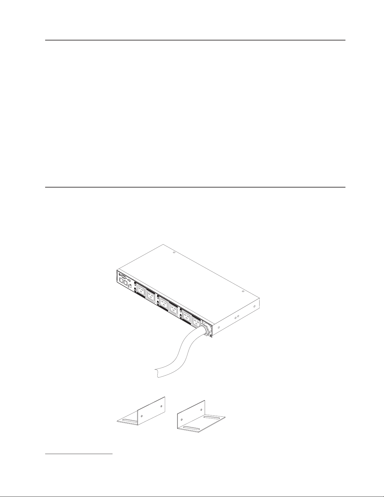
Parts that come with the PDU
Note: The illustrations in this document might differ slightly from your hardware.
The following parts come with the PDU:
vOne PDU (some models include detached line cords)
LAN
34
12
56
vTwo vertical-mounting brackets (for all rack cabinets)
1. One Uis equal to 4.45 cm (1.75 in.)
Chapter 1. Introduction 3
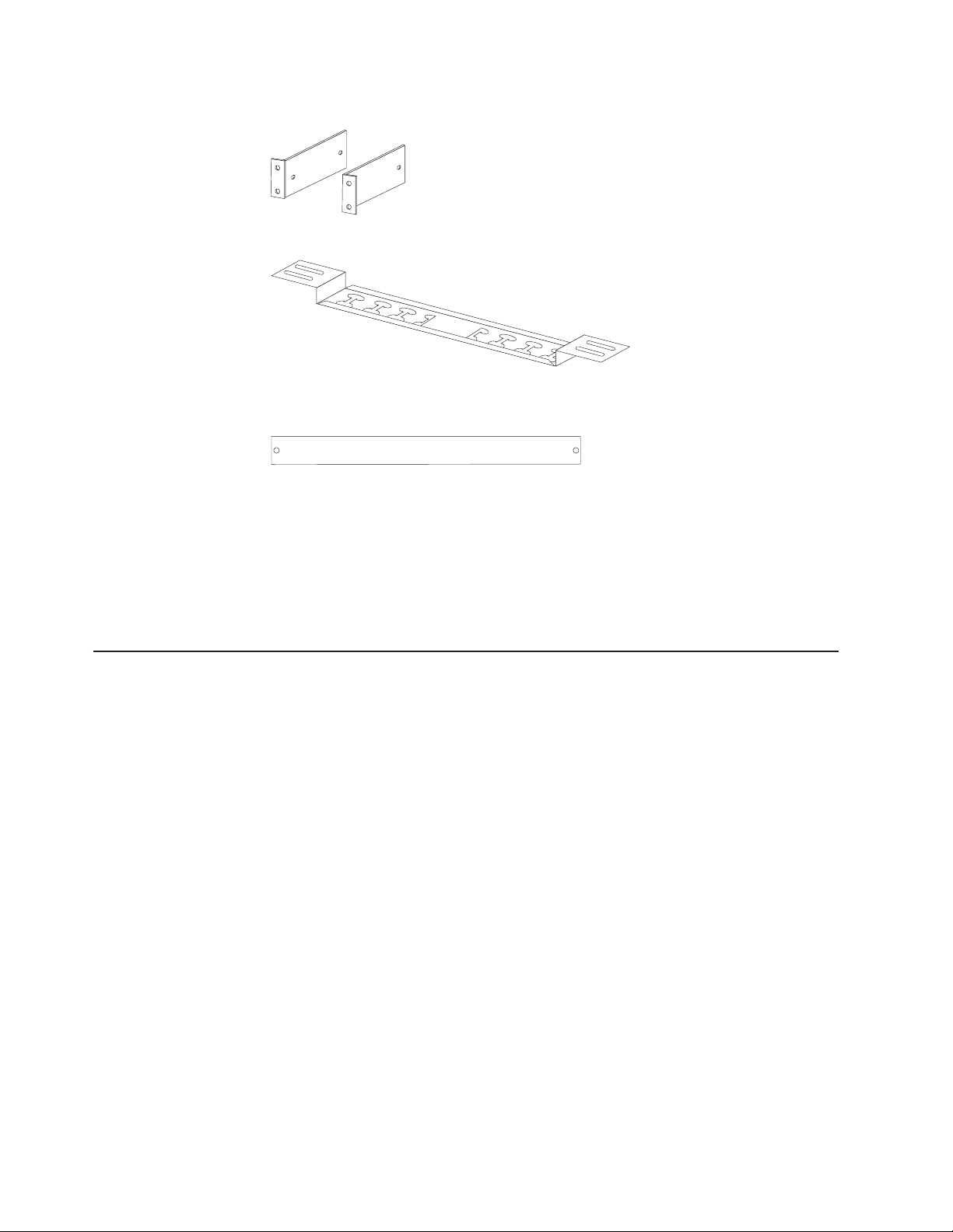
vTwo vertical-mounting brackets (for IBM Enterprise rack cabinets only)
vOne cable-management bracket (for vertical installations)
vOne DB9-to-RJ-45 cable
vOne 1-U blank filler panel
vMiscellaneous hardware kit (for attaching the mounting brackets to the PDU and
installing the PDU in arack cabinet)
vCable straps
Notes:
1. Power cables for devices that you will connect to the PDU do not come with the
PDU.
2. You will have some unused parts depending on how you install the PDU.
Features of the PDU
The features of the PDU include the following:
vVersatile sensors supported through environmental monitored probe inputs
vMonitor connected devices and sensors remotely
vMonitor the PDU manually, or remotely through aconsole or network
vComprehensive power management and flexible configuration through aWeb
browser, NMS, Telnet, SNMP, or HyperTerminal (console)
vConfigurable user security control
vUser-friendly interface to display input and output status
vDetailed data-logging for statistical analysis and diagnostics
vUpgrade utility for easy firmware updates
vEvent notification through SNMP trap or e-mail alerts
vDaily history report through e-mail
vAddress-specific IP security masks to prevent unauthorized access
4DPI C13 PDU+, DPI C19 PDU+, and DPI C19 3-phase PDU+: Installation and Maintenance Guide

Hardware components
The following sections provide descriptions of the front and rear components on the
PDU.
Front view
The following illustration shows the components and controls on the front of the DPI
C13 PDU+.
LAN
56
RS-232 serial
connector LED
RJ-45 LAN
connector
RJ-45
console connector
Operation
mode DIP switch
Input power
connector
Circuit breaker
Power outlets
2
1
34
The following illustration shows the components and controls on the front of the DPI
C19 PDU+ and the DPI C19 3-Phase PDU+.
Note: The IBM DPI C19 3-Phase PDU+ comes with an attached power cord.
56
34
LAN
12
RS-232 serial
connector LED Circuit breaker
RJ-45 LAN
connector
RJ-45
console connector
Operation
mode DIP switch
Power outlets
Input power
connector
Input power connector
Connect apower cord to this connector.
Note: Some PDU models come with an attached power cord.
Power outlets
You can connect adevice to each power outlet. There are either nine or 12
power outlets, depending on the PDU model.
RS-232 serial connector
Use the RS-232 serial connector to update the PDU firmware.
Green LED
The green LED shows the PDU input voltage status. When this LED is lit,
the PDU is receiving voltage. If the input voltage is too low, this LED is
flashing.
Chapter 1. Introduction 5

Operation mode DIP switch
Sets the mode of operation for the PDU. The default mode is S1 off, S2 off
for normal operation.
1=Off, 2=Off
The card will run normal operational firmware.
1=On, 2=On
The card will start in diagnostics mode.
1=On, 2=Off
Serial upgrade mode. You can upgrade the PDU firmware from the
serial connection if the network upgrade is not available.
1=Off 2=On
Read-only mode. The device will run normal operational firmware,
but all parameters of the device cannot be changed by auser.
Reset button
Resets the PDU for communication purposes only. Resetting the PDU does
not affect the loads.
RJ-45 console connector
Connect the DB9-to-RJ-45 cable that comes with the PDU to this connector
and to the serial (COM) connector on aworkstation or notebook computer
and use the workstation or notebook as aconfiguration console. You can
also connect an environmental monitored probe to this connector. The
environmental monitored probe monitors humidity and temperature. The
connection of an environmental monitored probe is automatically detected.
Green LED (on the left in ahorizontal orientation; on the top in avertical
orientation):
vThis LED is lit when the device is powered on.
vThis LED flashes while booting to indicate startup status.
Amber LED (on the right in ahorizontal orientation; on the bottom in a
vertical orientation)):
vThis LED flashes while communicating with aserver or computer or
when reading data from an environmental monitored probe.
RJ-45 Ethernet (LAN) connector
Use this connector to configure the PDU through aLAN. The Ethernet
connector supports 10/100 auto sense network connection.
Green LED (on left):
vThis LED is lit when connected to a100 Mb network.
vThis LED flashes while data is transmitted and received.
Amber LED (on right):
vThis LED is lit when connected to a10 Mb network.
vThis LED flashes while data is transmitted and received.
6DPI C13 PDU+, DPI C19 PDU+, and DPI C19 3-phase PDU+: Installation and Maintenance Guide

Rear view
The following illustration shows the rear of the DPI C13 PDU+.
The following illustration shows the power outlets on the rear of the DPI C19 PDU+
and the DPI C19 3-Phase PDU+.
3A
1A
5A
C13
outlets
Labels indicating associated
breakers on the front of the PDU
PDU load groups
The PDU load groups are described in the following tables.
Table 1. DPI C13 PDU+ load groups
Circuit breaker number Associated front outlets
11and 2
23and 4
35and 6
47and 8
59and 10
611 and 12
Table 2. DPI C19 PDU+ and DPI C19 3-phase PDU+ load groups
Circuit breaker number Associated front outlet Associated rear outlet
111A
22
333A
44
555A
66
Chapter 1. Introduction 7

8DPI C13 PDU+, DPI C19 PDU+, and DPI C19 3-phase PDU+: Installation and Maintenance Guide
This manual suits for next models
2
Table of contents
Other IBM Power Distribution Unit manuals


Popular Power Distribution Unit manuals by other brands

D&R ELECTRONICS
D&R ELECTRONICS PDU42WB Installation & operation manual

Eaton
Eaton MVS Instructional booklet

Siemens
Siemens WL Series instruction & installation guide

ABB
ABB pro E power PPIM0101 Instruction handbook

Pulizzi
Pulizzi IPC34XX-NET Series Specifications

Sonnen
Sonnen sonnenProtect 1300 operating instructions


