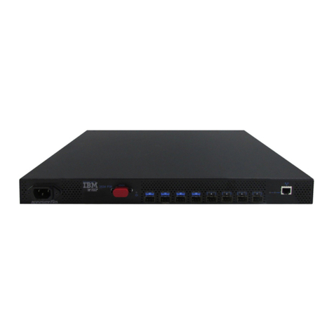
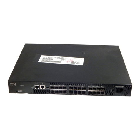
IBM SAN40B-4 - System Storage Switch Troubleshooting guide

IBM System Storage SAN40B-4
Installation, Service, and User’s Guide
Service information: 2498 -B40, 40E
GA32-0581-00
Read Before Using
This product contains software that is licensed under written license agreements. Your use of such software is subject to
the license agreements under which they are provided.


IBM System Storage SAN40B-4
Installation, Service, and User’s Guide
Service information: 2498 -B40, 40E
GA32-0581-00

Note:
Before using this information and the product it supports, read the information in “Notices” on page 41.
The following paragraph does not apply to any country (or region) where such provisions are inconsistent with local
law.
INTERNATIONAL BUSINESS MACHINES CORPORATION PROVIDES THIS PUBLICATION “AS IS” WITHOUT
WARRANTY OF ANY KIND, EITHER EXPRESS OR IMPLIED, INCLUDING, BUT NOT LIMITED TO, THE IMPLIED
WARRANTIES OF MERCHANTABILITY OR FITNESS FOR APARTICULAR PURPOSE. Some states (or regions) do
not allow disclaimer of express or implied warranties in certain transactions; therefore, this statement may not apply
to you.
©Copyright International Business Machines Corporation 2008. All rights reserved.
US Government Users Restricted Rights –Use, duplication or disclosure restricted by GSA ADP Schedule Contract
with IBM Corp.

Contents
Figures ............................v
Tables ............................ vii
Safety and environmental notices .................ix
Safety notices and labels .....................ix
Danger notices ........................ix
Caution notices ........................xi
Safety labels......................... xiii
Attention notices ....................... xiii
Rack safety .......................... xiv
Rack installation ....................... xiv
Rack relocation (19″rack) ....................xv
Product recycling and disposal ................... xvi
Battery return program ...................... xvii
For the European Union: .................... xvii
About this document ...................... xix
Product documents ....................... xix
Brocade documents ....................... xix
IBM and Brocade product matrix .................xx
Getting help ..........................xx
How to send your comments.................... xxi
Chapter 1. Introducing the SAN40B-4 switch .............1
Features and functions of the switch .................1
Supported connectivity ......................2
Port side of the switch.......................2
Port numbering ........................3
Nonport side of the switch .....................4
Field replaceable units (FRUs) ...................4
Additional port activation ......................4
ISL Trunking groups .......................5
Supported optional features.....................5
Chapter 2. Installing and configuring the switch ............7
Items included with the switch ....................7
Installation and safety considerations .................7
Electrical considerations .....................8
Environment considerations....................8
Cabinet considerations .....................8
Installing astand-alone switch....................8
Installing the switch into an EIA cabinet ................9
Time required .........................9
Items required ........................9
Installation instructions .....................10
Recommendations for cable management ...............14
Configuring the switch ......................15
Using the EZSwitch setup (optional) ................15
Providing power to the switch ..................15
Creating aserial connection ...................16
Setting the switch IP address ..................16
Setting the date and time ....................17
©Copyright IBM Corp. 2008 iii

Chapter 3. Operating the switch ..................21
Powering the switch on and off ...................21
Interpreting LED activity .....................21
LED locations ........................22
LED patterns ........................23
POST and boot specifications ...................25
POST ...........................25
Boot ............................25
Interpreting POST results .....................26
Maintaining the switch ......................26
Installing SFPs ........................26
Diagnostic tests .......................30
Customer field replaceable units (CRUs/FRUs) .............31
Time required ........................32
Items required ........................32
Replacement instructions ....................32
Managing the switch .......................33
Appendix. Product specifications .................35
Weight and physical dimensions ..................35
Facility requirements .......................35
Environmental requirements ....................36
Memory specifications ......................37
Data transmission ranges .....................37
Fibre Channel port specifications ..................38
Serial port specifications .....................38
Power supply specifications ....................38
Supported SFPs and HBAs ....................39
System specifications ......................39
Notices ...........................41
Trademarks ..........................43
Electronic emission notices ....................44
Federal Communications Commission (FCC) Class AStatement .....44
Industry Canada Class AEmission Compliance Statement ........44
Avis de conformité àla réglementation d’Industrie Canada ........44
European Union (EU) Electromagnetic Compatibility Directive.......44
Germany Electromagnetic Compatibility Directive ...........45
People’s Republic of China Class AElectronic Emission Statement ....46
Japan VCCI Class AITE Electronic Emission Statement.........46
Korea Class AElectronic Emission Statement ............46
Index ............................47
iv SAN40B-4 Installation, Service, and User’s Guide

Figures
1. Port side of the switch .............................2
2. Fibre Channel port numbering ..........................3
3. Non-port side of the switch ...........................4
4. Rack assembly ...............................10
5. Separating the inner and outer rails ........................11
6. Mounting the moving portion of the slide and mounting brackets to the switch ........12
7. Mounting the fixed portion of the rail and the locking brackets to the rack ..........13
8. Inserting slides into the rack rails .........................14
9. Detailed view, location of LEDs on the port side of the switch ..............22
10. Location of LEDs on the nonport side of the switch ..................22
11. SFP installation and bail closing .........................27
12. Removing an SFP ..............................29
13. Captive screws on the power supply fan assemblies..................32
14. Installing areplacement power supply fan assembly ..................33
©Copyright IBM Corp. 2008 v

vi SAN40B-4 Installation, Service, and User’s Guide

Tables
1. Sample caution notices ............................ xii
2. Brocade and IBM product and model number matrix ..................xx
3. Parts supplied with the rack-mount kit .......................11
4. Power status LED patterns, status, and recommended actions ..............23
5. System status LED patterns, status, and recommended actions .............23
6. Port LED patterns during normal operation .....................24
7. Ethernet LED patterns .............................24
8. Power supply status LED patterns, status, and recommended actions ...........25
9. Management options for the switch ........................33
10. Physical dimensions and weight of the switch ....................35
11. Facility requirements .............................35
12. Environmental requirements...........................36
13. Memory specifications .............................37
14. Data transmission ranges............................37
15. Serial cable pinouts ..............................38
16. Switch power supply specifications ........................38
17. General specifications .............................39
©Copyright IBM Corp. 2008 vii

viii SAN40B-4 Installation, Service, and User’s Guide

Safety and environmental notices
This section contains information about:
v“Safety notices and labels”
v“Rack safety” on page xiv
v“Product recycling and disposal” on page xvi
Safety notices and labels
When using this product, observe the danger, caution, and attention notices
contained in this guide. The notices are accompanied by symbols that represent the
severity of the safety condition. The danger and caution notices are listed in
numerical order based on their IDs, which are displayed in parentheses, for
example (D004), at the end of each notice. Use this ID to locate the translation of
these danger and caution notices in the IBM Systems Safety Notices (G229–9054)
publication, which is on the CD-ROM that accompanies this product.
The following notices and statements are used in IBM®documents. They are listed
below in order of increasing severity of potential hazards. Follow the links for more
detailed descriptions and examples of the danger, caution, and attention notices in
the sections that follow.
vNote: These notices provide important tips, guidance, or advice.
v“Attention notices” on page xiii: These notices indicate potential damage to
programs, devices, or data.
v“Caution notices” on page xi: These statements indicate situations that can be
potentially hazardous to you.
v“Danger notices”: These statements indicate situations that can be potentially
lethal or extremely hazardous to you. Safety labels are also attached directly to
products to warn of these situations.
vIn addition to these notices, “Safety labels” on page xiii may be attached to the
product to warn of potential hazards.
Danger notices
Adanger notice calls attention to asituation that is potentially lethal or extremely
hazardous to people. Alightning bolt symbol accompanies adanger notice to
represent adangerous electrical condition. Read and comply with the following
danger notices before installing or servicing this device.
DANGER
To prevent apossible shock from touching two surfaces with
different protective ground (earth), use one hand, when possible,
to connect or disconnect signal cables. (D001)
©Copyright IBM Corp. 2008 ix

DANGER
Overloading abranch circuit is potentially afire hazard and a
shock hazard under certain conditions. To avoid these hazards,
ensure that your system electrical requirements do not exceed
branch circuit protection requirements. Refer to the information
that is provided with your device or the power rating label for
electrical specifications. (D002)
DANGER
If the receptacle has ametal shell, do not touch the shell until
you have completed the voltage and grounding checks. Improper
wiring or grounding could place dangerous voltage on the metal
shell. If any of the conditions are not as described, STOP. Ensure
the improper voltage or impedance conditions are corrected
before proceeding. (D003)
DANGER
An electrical outlet that is not correctly wired could place
hazardous voltage on metal parts of the system or the devices
that attach to the system. It is the responsibility of the customer
to ensure that the outlet is correctly wired and grounded to
prevent an electrical shock. (D004)
The following general electrical danger notice provides instructions on how to avoid
shock hazards when servicing equipment. Unless instructed otherwise, follow the
procedures in the following danger notice.
xSAN40B-4 Installation, Service, and User’s Guide

DANGER
When working on or around the system, observe the following
precautions:
Electrical voltage and current from power, telephone, and
communication cables are hazardous. To avoid ashock hazard:
vConnect power to this unit only with the IBM provided power
cord. Do not use the IBM provided power cord for any other
product.
vDo not open or service any power supply assembly.
vDo not connect or disconnect any cables or perform
installation, maintenance, or reconfiguration of this product
during an electrical storm.
vThe product might be equipped with multiple power cords. To
remove all hazardous voltages, disconnect all power cords.
vConnect all power cords to aproperly wired and grounded
electrical outlet. Ensure that the outlet supplies proper voltage
and phase rotation according to the system rating plate.
vConnect any equipment that will be attached to this product to
properly wired outlets.
vWhen possible, use one hand only to connect or disconnect
signal cables.
vNever turn on any equipment when there is evidence of fire,
water, or structural damage.
vDisconnect the attached power cords, telecommunications
systems, networks, and modems before you open the device
covers, unless instructed otherwise in the installation and
configuration procedures.
vConnect and disconnect cables as described below when
installing, moving, or opening covers on this product or
attached devices.
To disconnect:
1. Turn off everything (unless instructed otherwise).
2. Remove the power cords from the outlets.
3. Remove the signal cables from the connectors.
4. Remove all cables from the devices.
To connect:
1. Turn off everything (unless instructed otherwise).
2. Attach all cables to the devices.
3. Attach the signal cables to the connectors.
4. Attach the power cords to the outlets.
5. Turn on the devices.
(D005)
Caution notices
Acaution notice calls attention to asituation that is potentially hazardous to people
because of some existing condition. Acaution notice can be accompanied by
different symbols, as in the examples below:
Safety and environmental notices xi

Table 1. Sample caution notices
If the symbol is... It means....
Ahazardous electrical condition with less
severity than electrical danger.
Agenerally hazardous condition not
represented by other safety symbols.
18-32 kg (39.7-70.5 lbs)
svc00167
18-32 kg (39.7-70.5 lbs)
Aspecification of product weight that
requires safe lifting practices. The weight
range of the product is listed below the
graphic, and the graphic and the wording of
the caution varies, depending on the weight
of the device.
P/N 18P5850-B
SJ000752
Apotential hazard of pinching the hand or
other body parts between parts.
Ahazardous condition due to moving parts
nearby.
Ahazardous condition due to the use of a
laser in the product. Laser symbols are
always accompanied by the classification of
the laser as defined by the U. S. Department
of Health and Human Services (for example,
Class I, Class II, and so forth).
Read and comply with the following caution notices before installing or servicing this
device.
CAUTION:
Energy hazard present. Shorting may result in system outage and
possible physical injury. Remove all metallic jewelry before
servicing. (C001)
CAUTION:
This part or unit is heavy but has aweight smaller than 18 kg (39.7
lb). Use care when lifting, removing, or installing this part or unit.
(C008)
CAUTION:
This product is equipped with a3-wire (two conductors and ground)
power cable and plug. Use this power cable with aproperly
grounded electrical outlet to avoid electrical shock. (C018)
CAUTION:
Servicing of this product or unit is to be performed by trained
service personnel only. (C032)
xii SAN40B-4 Installation, Service, and User’s Guide

Safety labels
As an added precaution, safety labels are often installed directly on products or
product components to warn of potential hazards. These can be either danger or
caution notices, depending upon the level of the hazard.
The actual product safety labels may differ from these sample safety labels:
DANGER
Hazardous voltage, current, or energy levels are present inside
any component that has this label attached. Do not open any
cover or barrier that contains this label. (L001)
DANGER
Rack-mounted devices are not to be used as ashelf or work
space. (L002)
DANGER
Multiple power cords. The product might be equipped with
multiple power cords. To remove all hazardous voltages,
disconnect all power cords. (L003)
DANGER
Hazardous voltage present. Voltages present constitute ashock
hazard, which can cause severe injury or death. (L004)
Attention notices
An attention notice indicates the possibility of damage to aprogram, device, or
system, or to data. An exclamation point symbol may accompany an attention
notice, but is not required. Asample attention notice follows:
Attention: Do not bend afibre cable to aradius less than 5cm (2 in.); you can
damage the cable. Tie wraps are not recommended for optical cables because they
can be easily overtightened, causing damage to the cable.
Safety and environmental notices xiii

Rack safety
Rack installation
DANGER
Observe the following precautions when working on or around your IT rack system:
vHeavy equipment—personal injury or equipment damage might result if
mishandled.
vAlways lower the leveling pads on the rack cabinet.
vAlways install stabilizer brackets on the rack cabinet.
vTo avoid hazardous conditions due to uneven mechanical loading, always install
the heaviest devices in the bottom of the rack cabinet. Always install servers and
optional devices starting from the bottom of the rack cabinet.
vRack-mounted devices are not to be used as shelves or work spaces. Do not
place objects on top of rack-mounted devices.
vEach rack cabinet might have more than one power cord. Be sure to disconnect
all power cords in the rack cabinet when directed to disconnect power during
servicing.
vConnect all devices installed in arack cabinet to power devices installed in the
same rack cabinet. Do not plug apower cord from adevice installed in one rack
cabinet into apower device installed in adifferent rack cabinet.
vAn electrical outlet that is not correctly wired could place hazardous voltage on
the metal parts of the system or the devices that attach to the system. It is the
responsibility of the customer to ensure that the outlet is correctly wired and
grounded to prevent an electrical shock.
(R001 part 1of 2)
CAUTION:
vDo not install aunit in arack where the internal rack ambient temperatures will
exceed the manufacturer’s recommended ambient temperature for all your
rack-mounted devices.
vDo not install aunit in arack where the air flow is compromised. Ensure that air
flow is not blocked or reduced on any side, front, or back of aunit used for air flow
through the unit.
vConsideration should be given to the connection of the equipment to the supply
circuit so that overloading of the circuits does not compromise the supply wiring or
overcurrent protection. To provide the correct power connection to arack, refer to
the rating labels located on the equipment in the rack to determine the total power
requirement of the supply circuit.
v(For sliding drawers) Do not pull out or install any drawer or feature if the rack
stabilizer brackets are not attached to the rack. Do not pull out more than one
drawer at atime. The rack might become unstable if you pull out more than one
drawer at atime.
v(For fixed drawers) This drawer is afixed drawer and must not be moved for
servicing unless specified by the manufacturer. Attempting to move the drawer
partially or completely out of the rack might cause the rack to become unstable or
cause the drawer to fall out of the rack.
(R001 part 2of 2)
xiv SAN40B-4 Installation, Service, and User’s Guide

Rack relocation (19″rack)
CAUTION:
Removing components from the upper positions in the rack cabinet improves
rack stability during relocation. Follow these general guidelines whenever you
relocate apopulated rack cabinet within aroom or building:
vReduce the weight of the rack cabinet by removing equipment starting at
the top of the rack cabinet. When possible, restore the rack cabinet to the
configuration of the rack cabinet as you received it. If this configuration is
not known, you must do the following:
–Remove all devices in the 32U position and above.
–Ensure that the heaviest devices are installed in the bottom of the rack
cabinet.
–Ensure that there are no empty U-levels between devices installed in the
rack cabinet below the 32U level.
–If the rack cabinet you are relocating is part of asuite of rack cabinets,
detach the rack cabinet from the suite.
–Inspect the route that you plan to take when moving the rack to
eliminate potential hazards.
–Verify that the route that you choose can support the weight of the
loaded rack cabinet. Refer to the documentation that came with your
rack cabinet for the weight of aloaded rack cabinet.
–Verify that all door openings are at least 760 x2030 mm (30 x80 in.).
–Ensure that all devices, shelves, drawers, doors, and cables are secure.
–Ensure that the four leveling pads are raised to their highest position.
–Ensure that there is no stabilizer bracket installed on the rack cabinet
during movement.
–Do not use aramp inclined at more than 10 degrees.
–Once the rack cabinet is in the new location, do the following:
-Lower the four leveling pads.
-Install stabilizer brackets on the rack cabinet.
-If you removed any devices from the rack cabinet, repopulate the rack
cabinet from the lowest position to the highest position.
–If along distance relocation is required, restore the rack cabinet to the
configuration of the rack cabinet as you received it. Pack the rack
cabinet in the original packaging material, or equivalent. Also, lower the
leveling pads to raise the casters off of the pallet and bolt the rack
cabinet to the pallet.
(R002)
Safety and environmental notices xv

Product recycling and disposal
This unit must be recycled or discarded according to applicable local and national
regulations. IBM encourages owners of information technology (IT) equipment to
responsibly recycle their equipment when it is no longer needed. IBM offers a
variety of product return programs and services in several countries to assist
equipment owners in recycling their IT products. Information on IBM product
recycling offerings can be found on IBM’s Internet site at http://www.ibm.com/ibm/
environment/products/index.shtml
Esta unidad debe reciclarse odesecharse de acuerdo con lo establecido en la
normativa nacional olocal aplicable. IBM recomienda alos propietarios de equipos
de tecnología de la informacion (TI) que reciclen responsablemente sus equipos
cuando éstos ya no les sean utiles. IBM dispone de una serie de programas y
servicios de devolucion de productos en varios países, afin de ayudar alos
propietarios de equipos areciclar sus productos de TI. Se puede encontrar
informacion sobre las ofertas de reciclado de productos de IBM en el sitio web de
IBM http://www.ibm.com/ibm/environment/products/index.shtml.
Note: This mark applies only to countries within the European Union (EU) and
Norway.
Appliances are labeled in accordance with European Directive 2002/96/EC
concerning waste electrical and electronic equipment (WEEE). The Directive
determines the framework for the return and recycling of used appliances as
applicable throughout the European Union. This label is applied to various products
to indicate that the product is not to be thrown away, but rather reclaimed upon end
of life per this Directive.
In accordance with the European WEEE Directive, electrical and electronic
equipment (EEE) is to be collected separately and to be reused, recycled, or
recovered at end of life. Users of EEE with the WEEE marking per Annex IV of the
WEEE Directive, as shown above, must not dispose of end of life EEE as unsorted
municipal waste, but use the collection framework available to customers for the
return, recycling and recovery of WEEE. Customer participation is important to
minimize any potential effects of EEE on the environment and human health due to
xvi SAN40B-4 Installation, Service, and User’s Guide

the potential presence of hazardous substances in EEE. For proper collection and
treatment, contact your local IBM representative.
Battery return program
This product may contain sealed lead acid, nickel cadmium, nickel metal hydride,
lithium, or lithium ion battery. Consult your user manual or service manual for
specific battery information. The battery must be recycled or disposed of properly.
Recycling facilities may not be available in your area. For information on disposal of
batteries outside the United States, go to http://www.ibm.com/ibm/environment/
products/index.shtml or contact your local waste disposal facility.
In the United States, IBM has established areturn process for reuse, recycling, or
proper disposal of used IBM sealed lead acid, nickel cadmium, nickel metal hydride,
and other battery packs from IBM equipment. For information on proper disposal of
these batteries, contact IBM at 1-800-426-4333. Please have the IBM part number
listed on the battery available prior to your call.
For Taiwan:
Please recycle batteries.
For the European Union:
Note: This mark applies only to countries within the European Union (EU).
Batteries or packaging for batteries are labeled in accordance with European
Directive 2006/66/EC concerning batteries and accumulators and waste batteries
and accumulators. The Directive determines the framework for the return and
recycling of used batteries and accumulators as applicable throughout the European
Union. This label is applied to various batteries to indicate that the battery is not to
be thrown away, but rather reclaimed upon end of life per this Directive.
Les batteries ou emballages pour batteries sont étiquetés conformément aux
directives européennes 2006/66/EC, norme relative aux batteries et accumulateurs
en usage et aux batteries et accumulateurs usés. Les directives déterminent la
marche àsuivre en vigueur dans l’Union Européenne pour le retour et le recyclage
des batteries et accumulateurs usés. Cette étiquette est appliquée sur diverses
batteries pour indiquer que la batterie ne doit pas être mise au rebut mais plutôt
récupérée en fin de cycle de vie selon cette norme.
Safety and environmental notices xvii

In accordance with the European Directive 2006/66/EC, batteries and accumulators
are labeled to indicate that they are to be collected separately and recycled at end
of life. The label on the battery may also include achemical symbol for the metal
concerned in the battery (Pb for lead, Hg for mercury and Cd for cadmium). Users
of batteries and accumulators must not dispose of batteries and accumulators as
unsorted municipal waste, but use the collection framework available to customers
for the return, recycling and treatment of batteries and accumulators. Customer
participation is important to minimize any potential effects of batteries and
accumulators on the environment and human health due to the potential presence
of hazardous substances. For proper collection and treatment, contact your local
IBM representative.
xviii SAN40B-4 Installation, Service, and User’s Guide
Other manuals for SAN40B-4 - System Storage Switch
1
Table of contents
Other IBM Switch manuals

IBM
IBM G8052 User manual

IBM
IBM pSeries Quick start guide

IBM
IBM 8271 Nways Ethernet LAN Switch User manual

IBM
IBM 8271 Nways Ethernet LAN Switch User manual

IBM
IBM SAN24B-6 User manual

IBM
IBM SAN48C-6 Manual

IBM
IBM 8270 Installation and maintenance instructions
IBM
IBM FC5022 User manual

IBM
IBM BNT G8124 User manual

IBM
IBM 8275 User manual